patent · US4270523
Heat storage apparatus and heat exchanger element for use therein
2 June 1981
Page 1 — bibliographic record
United States Patent (19) 11) 4,270,523 van Heel (45) Jun. 2, 1981
(54) HEAT STORAGE APPARATUS AND HEAT
EXCHANGER ELEMENT FOR USE
THEREN
75 Inventor: Joannes M. van Heel, Rotterdam, 4,131,158 12/1978 Abhat et al. ..................... 126/400X Netherlands 4,153,047 5/1979 Dumbeck ..................... 165/104 S X 73) Assignee: Stichting Bouwcentrum, Rotterdam, Primary Examiner-Albert W. Davis Netherlands Attorney, Agent, or Firm-Weingarten, Maxham &
Schurgin 21 Appl. No.: 19,461 57 ABSTRACT A heat storage apparatus comprising a plurality of heat 22 Filed: Mar. 9, 1979 exchanger elements mounted in a housing. Each ele ment has a central portion containing a storage medium, 30 Foreign Application Priority Data surrounded by portions through which a first and a second heat transfer fluid can be passed in heat contact
Mar. 23, 1978 NL Netherlands ......................... 7803171 with said storage medium. Means are provided for pass ing the heat transfer fluids from respective supply con 51 Int. Cl. .......................... F24J 3/02; F28D 21/00 duits through the apparatus through the respective por 52 U.S. C. .................................... 126/435; 126/436; tions of the heat exchanger elements to respective dis
Page 2
Drawing sheet — no readable text.
Page 3
it are secured together by means of a plurality of radi
HEAT STORAGE APPARATUS AND HEAT ally extending partitions or fins extending through by EXCHANGER ELEMENT FOR USE THEREN far the greater part of the length of the tubular body and the jackets. Preferably these partitions or fins consist of
This invention relates to an apparatus for storing 5 a material that is a good heat conductor, such as alumi solar heat collected by means of at least one collector. num. The tubular body, the jackets and the partitions or A prior apparatus for storing heat comprises a hous fins of each heat exchanger element may be made in one ing or vessel containing a heat storgae medium which piece. This promotes an economic production of such occupies at least part of the volume of said housing or elements. They can be made in one piece, for example, vessel, means for supplying a heat transfer fluid from 10 by casting or extrusion.
the collector, means for passing the transfer fluid If the apparatus according to the invention is used for through the apparatus in heat contact with the storage storing heat, the heat transporting fluid is passed from medium, means for discharging the transfer fluid to the the collectors through the storage apparatus, where it is collector, and means for passing a second heat transfer conducted through the heat exchanger elements around fluid through the apparatus in heat contact with the 15 the central members or tubes in which the storage me storage medium, and discharging it from the apparatus dium is contained. The storage medium may be any for further utilization. conventional medium, but we prefer media of the type Such a heat storage apparatus is well-known, and is known by the name of eutectic salts or mixtures thereof. frequently used in systems for heating buildings by Examples of eutectic salts are GLAUBER salt, means of solar heat. In such systems, solar heat is col 20 CaCl2.6H2O, and Ca(NO3)2.4H2O. Such eutectic salts lected by one or more collectors, disposed at a suitable pass at a specific temperature or temperature range location, for example, on the roof of the building. from a solid phase to a semi-liquid phase. This change in Through the collector or collectors, a heat transfer fluid phase requires a considerable amount of energy, so that or heat transporting fluid is pumped. As the heat trans such a eutectic salt is capable of absorbing a consider porting fluid, air or water is often used. The heat trans 25 able amount of heat during the transition. Conversely, porting fluid is warmed up in each collector. From the when it returns from the semi-liquid to the solid phase, collector, the fluid is conducted to the rooms in the a considerable amount of heat will be released. As a building which are to be heated. If there is no need for consequence, eutectic salts are highly suitable for use as direct utilization of the collected heat for heating the heat storage media. As the temperature range in which rooms, the heat transporting fluid is passed to the stor 30 the change in phase takes place commonly lies in the age apparatus, where the heat carried along is absorbed vicinity of 30-45 C., when eutectic salts are used as in the storage medium. When the heat stored is needed the storage medium the heat transporting medium is for heating purposes, heat transporting fluid is passed preferably air. In fact, such temperatures are less suit through the storage apparatus for absorbing heat from able for water as a transporting medium. There are the storage medium whereafter the heated transporting 35 more reasons why, in the system according to the pres fluid is conducted to the rooms to be heated. In addition ent invention, air is preferred to water as the transport to a system as described above, there may of course be ing medium. As a matter of fact, in a water system, provided a conventional heating system for supplemen attention must be paid to a good water-tightness of all tary heating. the conduits and couplings. On the other hand, in air It is an object of the present invention to improve the systems, the occurrence of possible minor leakages is storage apparatus described above, and to provide an less objectionable.
apparatus which operates extremely effectively. It is a In the heat storage apparatus according to the present further object of the invention to provide a suitable heat invention, the heat supplied by the heat transporting exchanger element for use in such a storage apparatus. medium is absorbed by the storage medium, whereafter According to the invention, the object stated is 45 the transporting medium is passed back to the collectors achieved with a storage apparatus comprising a plural for renewed heat absorption. When heat is to be with ity of heat exchanger elements disposed within the drawn from the storage apparatus according to the housing, each heat exchanger element comprising a invention, a heat transporting medium is passed through central portion containing the storage medium, sur the apparatus around the bodies containing the storage rounded by portions through which both heat transfer 50 medium for the absorption of heat from the storage fluids can be conducted. A plurality means in this con medium. The heat transporting medium may be the nection any suitable number. If so desired, the entire same medium as used for the supply of heat to the stor storage apparatus may consist of a single heat ex age apparatus. It is very possible, however, to use differ changer element. ent medium, for example, air for one purpose, and water Preferably, in the apparatus according to the inven 55 for the other. The medium thus heated in the apparatus tion, each heat exchanger element comprises a central is passed to the rooms to be heated, where it serves for tubular body for the storage medium, a first cylindrical heating purposes and gives up heat. Thereafter it is jacket disposed concentrically around, and secured to, again passed to the storage apparatus for renewed heat said tubular body so as to define a first cylindrical pas absorption. The storage apparatus according to the sage of substantially annular cross-sectional configura invention is preferably arranged so that the heat trans tion between the tubular body and the jacket, and a porting medium which supplies heat from the collectors second cylindrical jacket disposed concentrically is passed through the apparatus in one direction, around, and secured to, said first jacket so as to form a whereas the heat transporting medium which transports second cylindrical passage of substantially annular heat from the apparatus to the rooms to be heated is cross-sectional configuration between said first and said 65 passed through the apparatus in the opposite direction. second jacket. Thus, for example, when the heat exchanger elements In a suitable embodiment, the tubular body and the are constructed from concentric tubes, the transporting first and second jackets disposed concentrically around medium which supplies heat is passed through the pas
Page 4
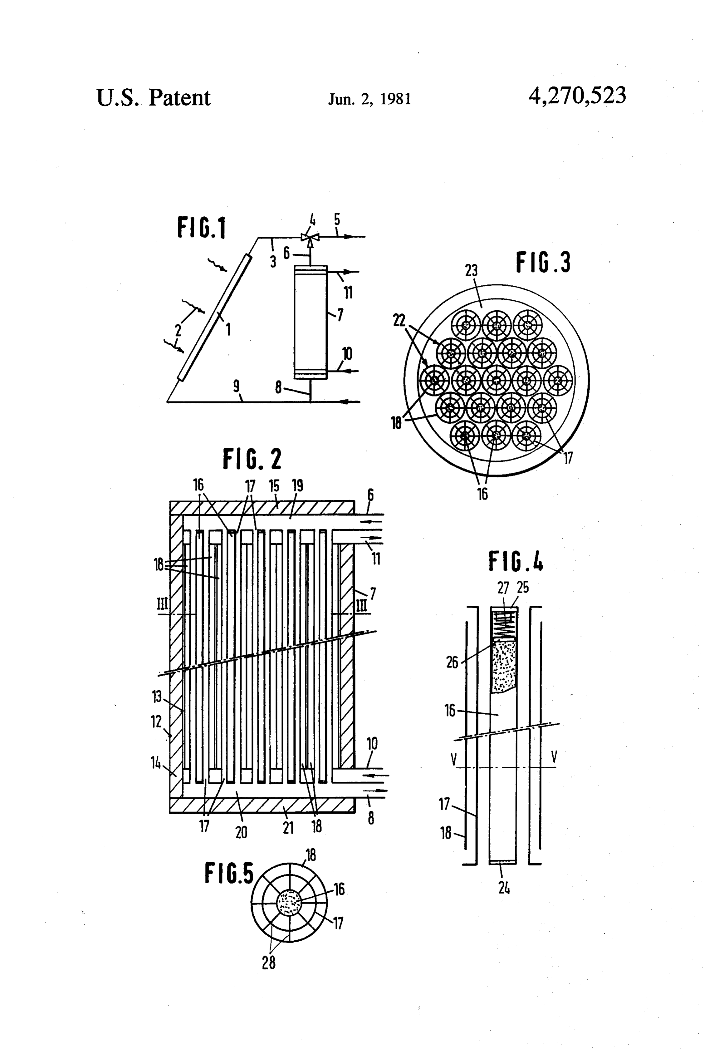
sage located closest to the central body containing the transporting medium through collector 1 and the con storage medium, whereas discharge of heat takes place duits to and from it.
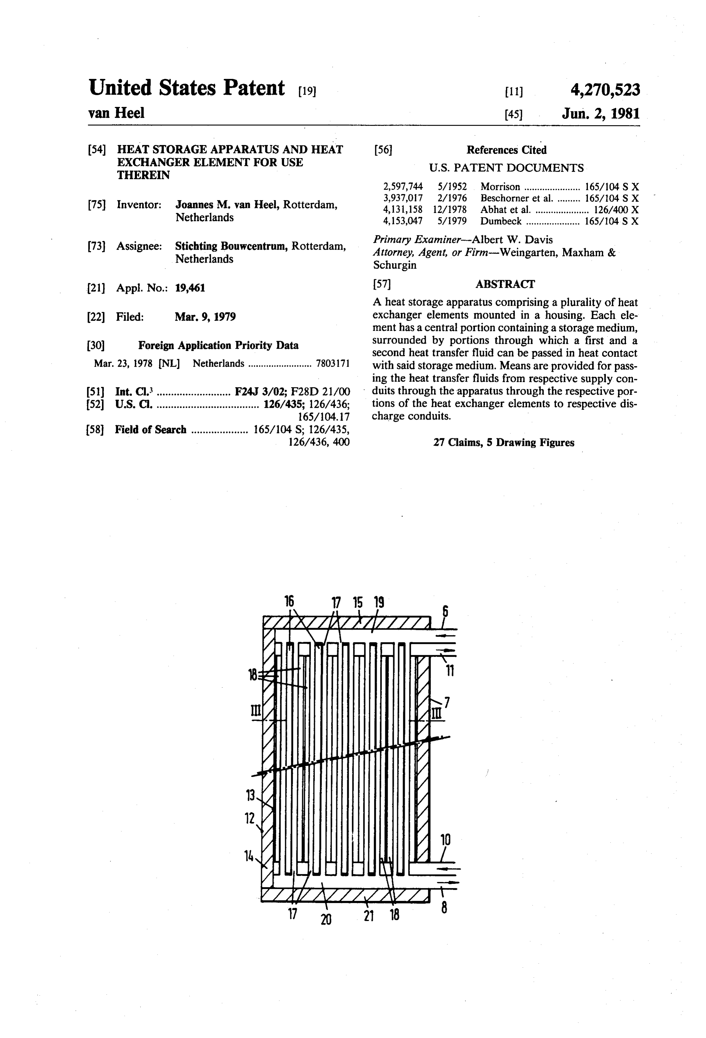
through the passage located more to the outside. FIG. 2 shows an embodiment of the heat storage The tubular body of the heat exchanger elements vessel 7 according to the invention in cross-sectional according to the present invention may be provided on 5 view, and FIG. 3 illustrates a sectional view of this both ends with a detachable cover for purposes of vessel, taken on the line III-III of FIG. 2. changing the storage medium and cleaning the tubular Vessel 7 is built up from a cylindrical outer jacket 2, body, should this be desirable after prolonged opera a cylindrical inner jacket 13 of smaller diameter than tion. Furthermore, there may be provided in the tubular jacket 12, and arranged concentrically within jacket 2. body, adjacent to at least one of the ends thereof, means The space between jackets 2 and 13 is filled with heat for compressing the storage medium in the body. Such insulating material 14. Jacket 12 has, for example, a compressing means are particularly useful when a eu diameter of 100 cm and jacket 13 a diameter of 80 cm, tectic salt is used as the storage medium, for ensuring so that the space within them is filled with a layer of that the medium is continuously in proper contact with approximately 10 cm insulating material. At the botton, the wall, so that its heat-transmitting capacity is at all 15 jackets A2 and 13 are secured in suitable manner to a times as great as possible. base plate 21, which is also constructed so as to virtually One embodiment of the invention will now be de prohibit the passage of heat from the interior of vessel 7 scribed with reference to the accompanying drawings, to the outside. At the top, vessel 7 is closed with a in which suitable cover 15, which is likewise provided with good FIG. 1 is a diagrammatic view of a portion of a heat heat insulation. Provided within vessel 7 are a plurality ing system comprising a collector and a storage appara of heat exchanger elements 22, as best shown in F.G. 3. tus according to the present invention; Insulating material 23 may be provided between the FIG. 2 is a cross-sectional view of an embodiment of outer elements 22 and the inner jacket 13 of vessel 7. the storage apparatus according to the invention; Each element 22 comprises a central tube 16 which is FIG. 3 is a cross-sectional view of the apparatus 25 closed at the top and bottom ends and filled with a shown in FIG. 2, taken on the line III-III of FIG. 2; suitable heat storage medium, for example, a material FIG. 4 is a cross-sectional view of an embodiment of known by the name of eutectic salt. Surrounding the the heat exchanger element of the apparatus according central tube 16 is a middle tube 17 of larger diameter, so to the invention; and as to form an annular passage between tubes 16 and 7. FIG. 5 is a cross-sectional view of the element shown 30 As illustrated in FIG. 2, heat exchanger elements 22 are in FIG. 4, taken on the line V-V of FIG. 4. mounted in vessel 7 so as to leave a space 20 between FIG. 1 diagrammatically shows a portion of a heating the ends of elements 22 and base plate 21 and a space 19 system for a building, for example, a house. The system between the ends and cover 15. The annular passages comprises a collector 1. Collector 1 can be of a conven between tubes 6 and 17 of each element 22 terminate at tional construction and serves for collecting solar heat, 35 the bottom in a space 20 and at the top in space 19. indicated by the arrows 2. The radiation 2 heats collec Connected to space 19 is conduit 16, which is passed tor 1 and a heat transporting medium therein. The heat through the wall of vessel 7 at a suitable location. Also transporting medium, which for example, may be air or connected to space 20 is conduit 8, likewise passed water, is passed through conduit 3 from collector 1 to through the wall of vessel 7 in a suitable manner. In the valve systern 4. If there is a need for the direct operation, heat transporting medium, for example air, further transportation of the medium to the rooms to be heated in a collector is passed through conduit 6 and heated, system 4 is adjusted so that the heat transporting introduced into space 19. Thence the medium moves medium is passed further into the house through con through the annular passages around tubes 6 to space duit 5. If there is no need for the medium to be passed 20, during which passage heat is absorbed by, and directly to rooms to be heated, the valve system 4 is 45 stored in, the storage medium within tubes 16. Subse adjusted so that the medium is passed through conduit 6 quently the heat transporting medium is discharged to storage vessel 7. After being passed through storage from vessel 7 through conduit 8.
vessel 7, the medium, which in storage vessel 7 gives up Arranged concentrically around the middle tube 17 a large part of the absorbed heat to a heat storage me of each element 22 is an outer tube 18. Tube 18 is of dium present within vessel 7, is passed through conduit 50 larger diameter than tube 17, so that there is an annular 8 and conduit 9 back to collector 1, where heat from the passage between the two tubes. At the top of each ele solar radiation 2 is again absorbed. If the heat transport ment 22, these passages are interconnected and con ing medium has been passed directly to rooms to be nected to conduit 11 passed through the wall of vessel 7. heated, it is thereafter also returned through conduit 9 At the bottom of each element 22, the passages between to collector 1. A suitable pump or fan (not shown) is 55 tubes 7 and 18 are also interconnected and connected arranged in the system for transporting the transporting to conduit 10, passed through the wall of vessel 7. If and medium through collector 1 and the conduits. when required, a heat transporting medium can be sup If there is a need for the supply of heat to the rooms plied through conduit 10 and conducted through the of the house at a moment when the collector does not passages between tubes 17 and 18, where it can absorb collect solar radiation, for example during the night, 60 heat from the storage medium within tubes 16. Natu heat transporting medium is passed through conduit 10 rally, to this effect, means should be provided for trans to storage vessel 7, subsequently through storage vessel porting this heat from the storage medium to at least the 7, where heat is absorbed from the storage medium wall of tubes 17, as will be described in more detail present therein, and subsequently through conduit 11 to hereinafter. After the heat transporting medium has the rooms to be heated. At that time, the valves and 65 absorbed heat from the storage medium within tubes 6, pump(s) or other means for transporting the heat trans it is passed through conduit 11 to rooms to be heated in porting medium throughout the system are preferably the building where the heat storage apparatus is in adjusted so that there is no transportation of the heat stalled.
Page 5
The construction of a heat storage element as prefera at least one solar collector having means for passing a bly implemented in accordance with the present inven first heat transfer fluid therethrough; tion is illustrated in more detail in FIGS. 4 and 5. As a housing;
described above, the element comprises a central tube a plurality of heat exchange elements disposed within 16, closed at both ends, and containing a suitable heat said housing, each of said heat exchange elements storage medium. Disposed concentrically around tube comprising a heat storage medium disposed cen 16 are a tube 17 of larger diameter and a tube 18 of still trally therein and occupying at least a portion of larger diameter. As shown by the cross-sectional view said housing;
of FIG. 5, tubes 16, 17 and 18 are secured together by means for circulating said first heat transfer fluid means of a plurality of radial fins 28, Fins 28 preferably 10 from said solar collector through said heat ex extend throughout the length of element 22. Tubes 16, change elements in heat exchange relationship with 17 and 18 and fins 28 are preferably made of a material said heat storage medium; which is a good heat conductor, for example, alumin means for returning said first heat transfer fluid from ium. The entire construction of tubes and ribs is suitably each of said heat exchange elements to said solar made in one piece, for example, by casting or extruding. 15 collector; and
As the material of the element is a good heat conductor, means for passing a second heat transfer fluid through when hot heat transporting medium is supplied in the each of said heat exchange elements in heat ex passage between tubes 16 and 17, this heat will be rap change relationship with said storage medium and idly transmitted to the heat storage medium in tube 16. for thereafter discharging said second heat transfer Conversely, heat will be rapidly transmitted from the 20 fluid from said apparatus, said first and second heat storage medium to a heat transporting medium which is transfer fluids being isolated from each other. passed through the passage between tubes 17 and 18. 2. Apparatus as claimed in claim 1, wherein each heat In order that, after prolonged use of element 22, the exchange element comprises:
heat storage medium in tube 16 may be changed, and if a central tubular body containing said storage me desired, tube 16 may be cleaned, tube 16 is closed at the 25 dium;
bottom, as shown in FIG. 4, with a removable cover 24, a first cylindrical jacket disposed concentrically for example, a threaded cover, which is screwed to the around, and secured to, said tubular body to define end concerned. At the top, tube 16 is also closed with a a first cylindrical passage having a substantially removable cover 25, which may also be a screw cover. annular cross-sectional configuration and being Provided at the top within tube 16 is a further compres 30 located between said tubular body and said first sion member 26, for example, in the form of a plate of jacket; and suitable material. Compression member 26 is dimen a second cylindrical jacket disposed concentrically sioned so as to be capable of moving up and down around, and secured to, said first jacket to form a within tube 16 without the storage medium being capa second cylindrical passage having a substantially ble of moving upwards between members 26 and the 35 annular cross-sectional configuration and being inner wall of tube 16. Member 26 is maintained under located between said first and said second jacket. pressure onto the storage medium by means of, for 3. Apparatus as claimed in claim 2, wherein said tubu example, a spring 27 arranged between cover 25 and lar body and said first and said second jackets are se member 26. In operation, the heat storage medium will cured together by a plurality of radially extending fins expand when it absorbs heat, so that member 26 is extending along at least a portion of the length of said moved upwards. When the material shrinks again after tubular body and said first and said second jackets. giving up its heat, member 26 will ensure that the entire 4. Apparatus as claimed in claim 2 or 3, wherein said volume under member 26 remains filled with storage tubular body includes a detachable cover disposed at medium and that, in particular, a good contact between each end thereof.
the storage medium and the wall of tube 16 is ensured. 45 5. Apparatus as claimed in claim 4 wherein said circu Other embodiments of the compression system are lating means passes said first heat transfer fluid through possible. Thus, instead of a compression member 26, a said first cylindrical passage in one direction and said resilient diaphragm may be arranged in the tube direct passing means passes said second heat transfer fluid over the storage medium, and a gas under pressure can through said second cylindrical passage in a second be provided between cover 25 and the diaphragm. 50 direction opposite to said one direction of said first heat When the storage medium expands, this will push the transfer fluid.
diaphragm upwards; as a consequence the superjacent 6. Apparatus as claimed in claim 2 or 3, further com gas is compressed. When the storage medium contracts prising means for compressing said storage medium in again, it will be kept properly compressed by the action said tubular body, said compressing means being dis of the compressed gas above the diaphragm. 55 posed within said tubular body adjacent at least one of Although the invention has been shown and de the ends thereof.
scribed with reference to a preferred embodiment of the 7. Apparatus as claimed in claim 6 wherein said circu storage apparatus, it will be clear that the invention is lating means passes said first heat transfer fluid through not so limited. In particular, the arrangement of the heat said first cylindrical passage in one direction and said exchanger elements in vessel 7 can be modified. Fur 60 passing means passes said second heat transfer fluid thermore, the shape of elements 22 can be varied. The through said second cylindrical passage in a second functions of the passages between tubes 16 and 17 and direction opposite to said one direction of said first heat between tubes 17 and 18 are interchangeable. Other transfer fluid.
variants of the embodiment shown and described can be 8. Apparatus as claimed in claim 3, wherein at least conceived by those skilled in the art without departing 65 said fins of each heat exchanger element are comprised from the scope of the invention. of a heat conducting material.
I claim: 9. Apparatus as claimed in claim 8 wherein said circu 1. An apparatus for storing solar heat comprising: lating means passes said first heat transfer fluid through
Page 6
said first cylindrical passage in one direction and said passages of each of said heat exchange elements in passing means passes said second heat transfer fluid heat exchange relationship with said heat storage through said second cylindrical passage in a second medium and for thereafter discharging said second direction opposite to said one direction of said first heat heat transfer fluid from said apparatus. transfer fluid. 5 17. Apparatus as claimed in claim 12 wherein each of 10. Apparatus as claimed in claim 3, wherein said said heat exchanger elements further comprises a plural tubular body, said first jacket and said second jacket and ity of fins extending radially from said central tubular said fins of each heat exchanger element are made in one body through said first and said second cylindrical jack piece. ets for securing together said central tubular body, said 11. Apparatus as claimed in claim 10 wherein said O first cylindrical jacket and said second cylindrical circulating means passes said first heat transfer fluid jacket, said radially extending fins extending axially through said first cylindrical passage in one direction along most of the length of said central tubular body and said passing means passes said second heat transfer and said first and said second cylindrical jackets. fluid through said second cylindrical passage in a sec 18. Apparatus as claimed in claim 16 or 17 wherein ond direction opposite to said one direction of said first 5 said central tubular body of each of said heat exchange heat transfer fluid. elements comprises a detachable cover disposed at each 12. Apparatus as claimed in claim 2 or 3 wherein each end thereof.
of said heat exchange elements further comprises means 19. In an apparatus for storing solar heat which in for compressing said storage medium in said tubular cludes body, said compressing means being disposed within passing at least one solar collector having means for a first heat transfer fluid passing therethrough, a said tubular body adjacent at least one end thereof. housing, a heat exchanger disposed within said housing, 13. Apparatus as claimed in claim 2 or 3 wherein said means for circulating said first heat transfer fluid from circulating means passes said first heat transfer fluid said solar collector through said heat exchanger and through said first cylindrical passage in one direction and said passing means passes said second heat transfer 25 back to said solar collector, and means for passing a fluid through said second cylindrical passage in a sec second and for heat transfer fluid through said heat exchanger thereafter discharging said second heat transfer ond direction opposite to said one direction of said first fluid from said apparatus, a plurality of heat exchange heat transfer fluid.
14. Apparatus as claimed in claim 1, wherein said said heat exchangewithin elements disposed said heat exchanger, each of elements of said heat exchanger storage medium is comprised of a eutectic salt. 30 15. Apparatus as claimed in claim 14, wherein said comprising:a central tubular body containing a heat storage me circulating means passes said first heat transfer fluid dium; and through said first cylindrical passage in one direction, and said second heat transfer fluid passing means passes heat transfer portions surrounding said central tubu said second heat transfer fluid through said second cy 35 lar body through which each of said first and said lindrical passage in a second direction opposite to said second heat transfer fluids are conducted in heat one direction of said first heat transfer fluid. exchange relationship with said heat storage me 16. An apparatus for storing solar heat comprising: dium, said first and said second heat transfer fluids at least one solar collector having means for passing a being isolated from one another. first heat transfer fluid therethrough; 20. The heat exchange elements as claimed in claim a housing; 19 wherein said heat transfer portions comprise: a plurality of heat exchange elements disposed within a first cylindrical jacket disposed concentrically said housing, each of said heat exchange elements around and secured to said tubular body to define a comprising: first cylindrical passage located between said tubu a central tubular body containing a heat storage 45 lar body and said first cylindrical jacket and having medium; a substantially annular cross-sectional configura a first cylindrical jacket disposed concentrically tion; and around and secured to said central tubular body a second cylindrical jacket disposed concentrically to define a first cylindrical passage located be around and secured to said first cylindrical jacket tween said central tubular body and said first 50 to form a second cylindrical passage located be cylindrical jacket and having a substantially an tween said first cylindrical jacket and said second nular cross-sectional configuration; and cylindrical jacket and having a substantially annu a second cylindrical jacket disposed concentrically lar cross-sectional configuration. around and secured to said first cylindrical 21. The heat exchange elements as claimed in claim jacket to form a second cylindrical passage be 55 22 wherein each heat exchange element further com tween said first cylindrical jacket and said sec prises a plurality of fins extending radially from said ond cylindrical jacket and having a substantially tubular body through said first cylindrical jacket and annular cross-sectional configuration; said second cylindrical jacket to secure together said means for circulating said first heat transfer fluid tubular body, said first jacket and said second jacket, from said solar collector through one of said first said fins extending axially along most of the length of and said second cylindrical passages of each of said said tubular body and most of the length of each of said heat exchange elements in heat exchange relation first jacket and said second jacket.
ship with said heat storage medium; 22. The heat exchange elements as claimed in claim means for returning said first heat transfer fluid from 20 or 21 wherein said tubular body comprises a detach each of said heat exchanger elements to said solar 65 able cover disposed at each end thereof. collector; and 23. The heat exchange elements as claimed in claim means for passing a second heat transfer fluid through 22 further comprising means for compressing said stor the other of said first and said second cylindrical age medium within said tubular body, said compressing
Page 7
means being disposed within said tubular body adjacent 26. The heat exchange elements as claimed in claim at least one end thereof. 19 wherein said storage medium is comprised of a eutec
24. The heat exchange elements as claimed in claim 27. The heat exchange elements as claimed in claim 21 wherein at least said fins are comprised of a heat 5 20 wherein said circulating means passes said first heat conducting material. transfer fluid through said first cylindrical passage in 25. The heat exchange elements as claimed in claim one direction and said passing means passes- said - - second 21 wherein said tubular body, said first jacket, said heat transfer fluid through said second cylindrical pas Were Sa y, J s sage in a second direction opposite to said one direction second jacket and said fins are formed together in one 10 of said first heat transfer fluid.
piece. k is :
Provenance
- Collection
- Cited prior art
- Original PDF
- patentimages.storage.googleapis.com →
- Filed
- 1979-03-09
- Pages
- 7
- Method
- pdftotext (the PDF's own text layer) + pdftoppm 300dpi page scans
- Source
- Google Patents bibliographic record
- Granted
- 1981-06-02
- Inventors
- Joannes M. Van Heel; Stichting Bouwcentrum
- Transcribed from
- patentimages.storage.googleapis.com →