patent · US1753227
Solar water-heating system
8 April 1930
Page 1
Drawing sheet — no readable text.
Page 2
Drawing sheet — no readable text.
Page 3
Patented Apr. 8, 1930 1,753,227 UNITED STATES PATENT office
HENRY A. WHEELER, FRANK J. BENTZ, AND JAMES I...MASON, OF MIAMI, FLORIDA,
ASSIGNORS, BY DIRECT AND MESNE ASSIGNMENTS, OF THREE-FOURTHS TO SATD.
FRANK J. BENTZAND ONE-FOURTH TO L. E. BENTZ
SOLAR WATER-HEATING SYSTEM
Application filed August 22, 1928, serial No. 301,370.
In numerous localities in which the heat complished by reference to the accompanying from the sun is sufficiently intense, solar water drawings.
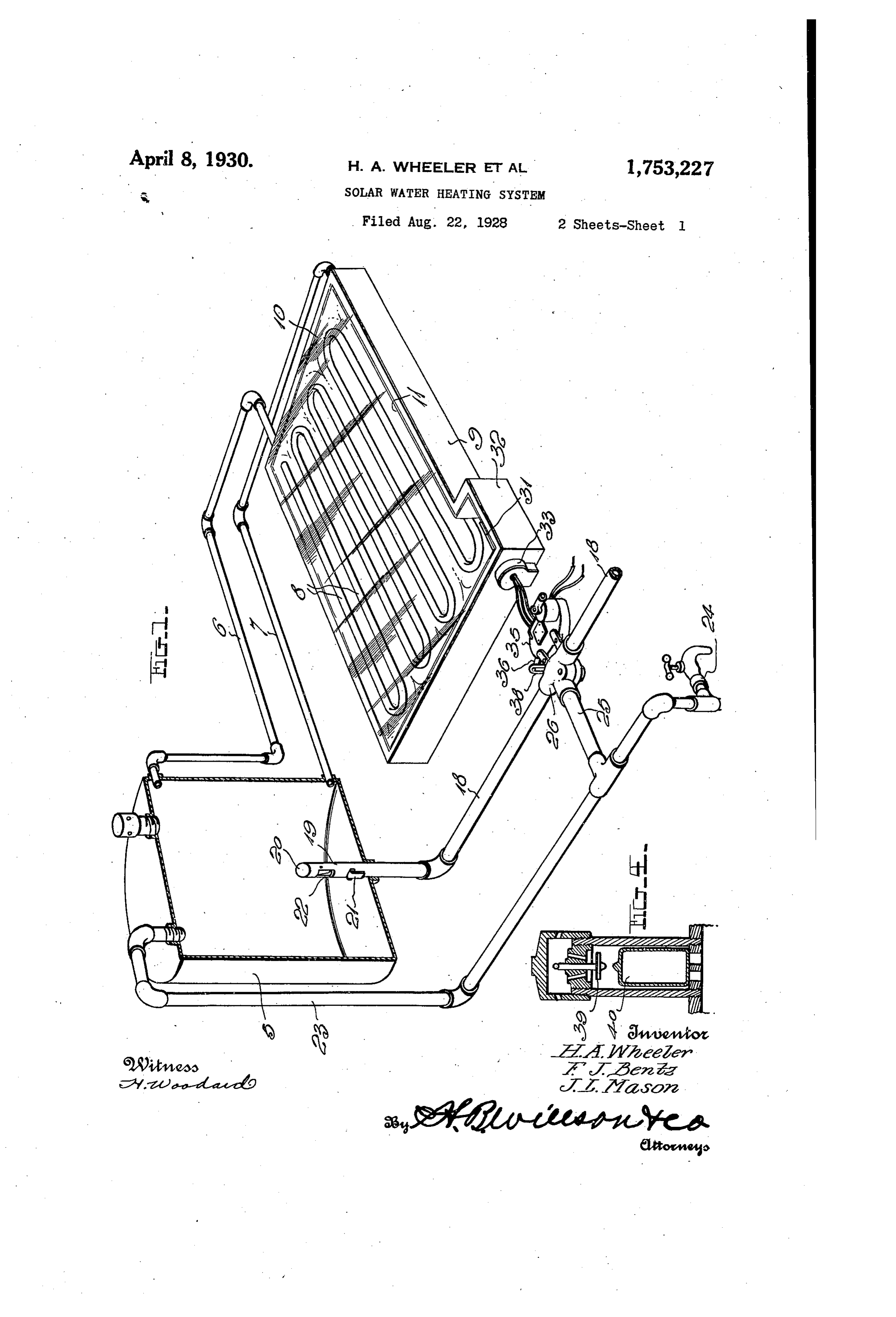
Fig. 1 is a perspective view partly in sec heaters are in quite extensive use. A well tion.
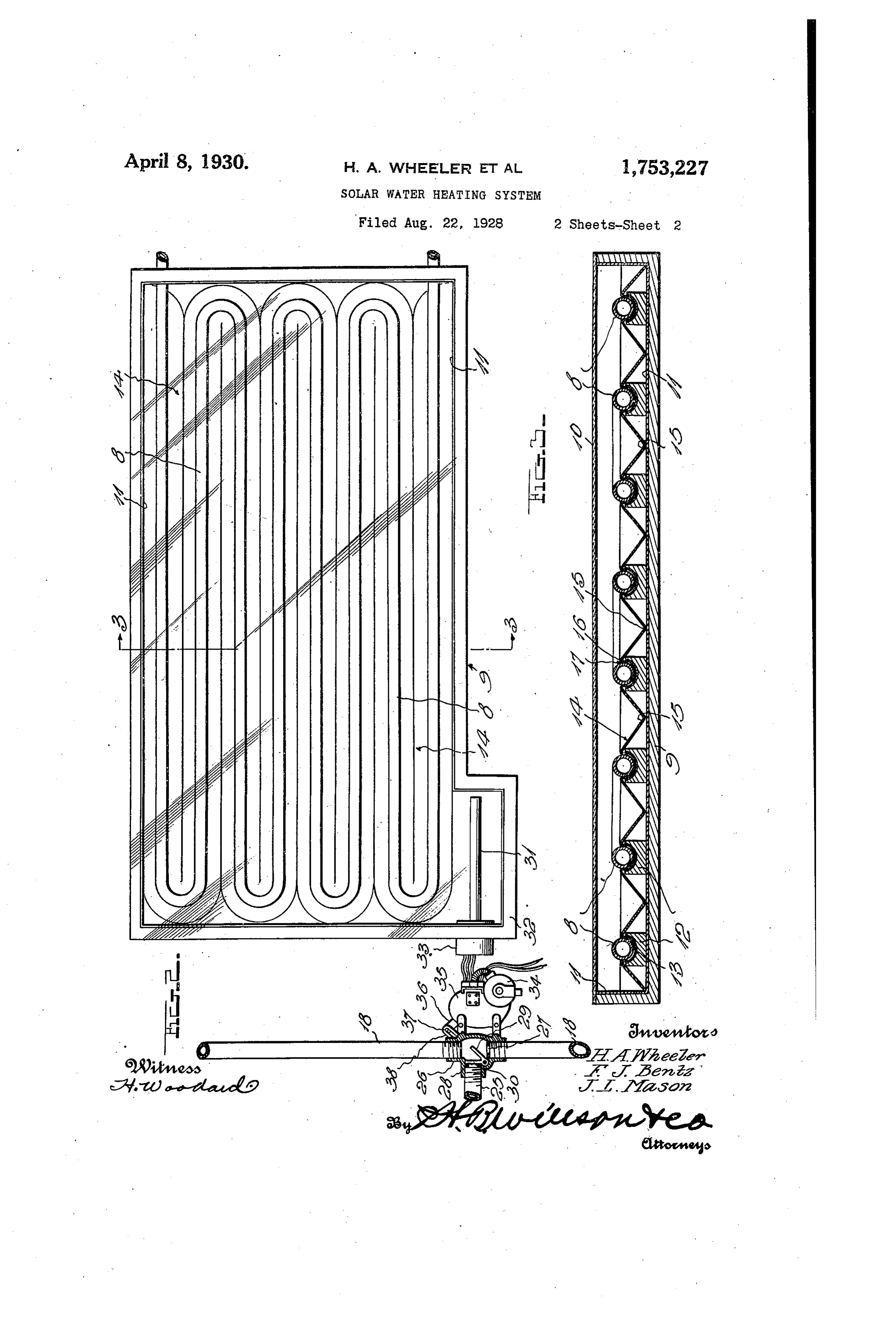
known heater of this character embodies a wa 5 ter tank and Sun-heated means communicat ingFig. 2 is a top plan view of the water heat 55 means and associated parts.
ing with said tank for heating the water Fig. 3 is an enlarged transverse sectional therein. The lower end of the tankisconnect view ed with a supply pipe for water under pres Fig.on4 line 3-3 of Fig. 2. is a vertical sectional view through sure and the upper end of the tankisprovided the air valve 0 with a hot water discharge pipe which extends storage tank. at the upper end of the water 60 to any desired point or points and is provided The general construction shown in the with one or more hot water discharge spigots. drawings is preferably followed and while Opening of any spigot relieves the pressure in the tank and the water under pressure. such subject matter will be herein specifically described, it is to be understood that within 65 ls from the supply pipe consequently forces hot the scope of the invention as claimed, varia water from the upper end of said tank as the cold water enters. This type of system oper tions may be made.
ates advantageously throughout the day as ageThe numeral 5 denotes a hot water stor tank with which water circulating pipes long as the rays of the sun are being effectively 6 and 7 communicate, 20 utilized. However, after sundown, the run nected to the ends of said pipes being con- 70 ning of cold water into the tank each time hot embodies parallel pipesa 8.heatingThese coil which pipes are water is withdrawn therefrom, gradually de within a shallow flat casing 9 having a glass creases the temperature of the water, with the result that there is none left for morning use. top with10,thethe entire inner side of said casing, exception of its top, being provided * It is the primary object of our inventionhow with heat-insulating material 11. The pipes ever to overcome this difficulty by providing a are supported by longitudinally channeled novel improvement, by the use of which no 8Wooden coldwater is admitted paratus reaches the endtoof theitstank the ap material,strips afterperiod, heating 12 or strips of other desired said pipes being disposed in the until the next morning, and whereby the hot terial channels of said strips. Heat-insulating ma- 80 water stored in the tank over night may be pipes and 13 is preferably interposed between the withdrawn in desired quantities by gravity. in preventing strips to co-operate with the latter By thus preventing the entrance of cold water said pipes. A downward loss of heat from metal sheet 14 of any desired into the tank after the heating period is at an
end, the hot water stored in the tank will re itmaterial to readily to the pipes absorb heat 8, is provided and conduct throughout the 8 main sufficiently warm over night for morn area ing use. Then, when the rays of the sun are with of the casing 9. This sheet is provided again to be effectively utilized, the system is of thealternate channels 15 and ridges 16, each latter being formed with a longitudinal conditioned to function so that whenever hot
water is withdrawn, cold water enters to take slot and 17. The pipes 8 are inset in these slots 90 may be soldered or otherwise secured to its place, and to be heated. the sheet 14. a t A further object of the invention is to pro The construction described insures that vide automatic means controlled by a thermo maximum heating efficiency be obtained from . 45 stat or analogous contrivance for condition the rays of the sun to heat the water in the 9 ing the apparatus both for night-use and day. tank 5.
Se. - . . A supply pipe 18 leads to the lower por With the foregoing in view, the invention tion of the tank 5 for supplying cold water resides in the novel subject matter hereinafter under pressure to the latter as hot water is 50 described and claimed, description being ac withdrawn. For purposes to appear, this
Page 4
pipe 18 terminates in an upstanding portion ating the dual valve above described, said 19 in the lower end of the tank 5, the upper means preferably embodying a thermostat extremity of this portion 19 being closed as at 31 controlled by the sun heat rather than the 20. Pipe portion 19 is provided with an out Water heat, together with operating connec Wardly opening check valve 21 near the bot tions between this thermostat and the valve. 70 tom of the tank 5 and with an inwardly open In the present showing, the thermostat 31 is ing check valve 22 positioned above said valve within an offset portion 32 of the casing 9, 21. These parts also function as hereinafter and said thermostat controls an electric explained.
O fleading from the upper end of the tank 5, switch 33. which in turn controls an electric motor 34. This motor is connected by a train 75 is a hot water discharge pipe 23 leading to of gearing within the housing 35, with an one or more spigots. 24. Upon opening of arm 36, and this arm has an appropriate one of the spigots, pressure in the tank 5 is connection 37 with an arm 38 secured to the relieved, with the result that cold water en valve 29-30. At the end of the day, when 15 ters through the pipe 18 and the check valve the sun heat is sufficiently diminished, the 80 21, driving hot water from the top of the tank thermostat 31, switch 33, motor 34, etc. op out through the discharge pipe 23. The hot erate to move the valve to its other position water is discharged in this way and replaced from that shown in Fig. 2, permitting draw by cold water as long as the rays of the sun ing off of hot water from the tank 5 by grav 20 can be effectively utilized for heating the ity. In the morning however, when the sun 85 water in the tank. However, provision is heat again raises the temperature of the ther made whereby no cold water can enter the mostat, it and associated parts again effect tank after sundown and whereby the hot with positioning of the valve as seen in Fig. 2, water which is stored within such tank may the result that each time hot water is 25 be drawn from it by gravity. These ends withdrawn, cold water enters to take its 90 can be obtained in various ways but the sub place. . . .
ject matter shown will suffice for illustrative theNaturally, the water at the lower end of tank 5 is always at a lower temperature
A branch pipe 25 is connected with the hot than that at the upper end thereof. Hence, 30 water discharge pipe 23, preferably near the the pipe portion 19 and the check valve 22 95 are provided to prevent drawing of the rela tank 5. This branch pipe communicates also tivelv cold water from the lower end of the with pipe a18valve casing 26 with is provided. In thewhich the26, casing supply two tank when the system is operating by gravity.
valve seats 27 and 28 have been shown, When the tank 5 is being filled with water one under.
for the supply pipe 18 and one for the branch valve pressure entering through the check 00 25. A movable valve member is pivotally 21, it is essential that air be exhausted mounted in the casing 26 and embodies a valve from the upper end of said tank. Similarly, portion 29 co-operable with the seat 27 and when water is being drawn from the tank by gravity, it is necessary that air be admitted another valve portion 30 co-operable with the 40 seat 28, these portions being so related that to the upper end of the tank. To accomplish 05 when one is needed, the other is open. these ends, an air valve is provided in the When the dual valve above described is top of the tank or at other desired location. in the position shown in Fig. 2, the apparatus tionThis valve may be of the detailed construc is in condition for day use, the branch 25 be In theshown in Fig. 4 or of other desired form. view under consideration, the movable O ing then cut off from the pipe 18 and free valve member 39 is closed by a float 40 when passage of water being permitted through the latter to the tank 5. This cold water en the water in the tank rises sufficiently, but as the water level recedes, the float drops ters the tank at the lower extremity of the and the valve is self-opening as shown in the latter through the check valve 22. However,
SO when the valve is moved to its opposite posi drawing. 5 By the use of our improvements, we save tion, it closes the seat 27 and places the approximately branch 25 is communication with the portion is being wasted 50% at of the hot water which present with Solar heating of the pipe 18 between the valve and the tank systems of the type to which 5. Thus, upon opening of the spigot 24, hot referred. Not only do we saveweinhave hot above water 20 water from the tank will enter the pipe 18 by the use of the system, but with a smaller through the check valve 22, will travel through a portion of this pipe to the valve and less expensive tank and water-heating casing 26, and through this casing and the quantityweof are means, enabled to deliver a larger hot water. Ordinarily, an eight branch 25, will travel to the hot water dis
charge pipe 23 through which it is conducted hundred gallon tank with six heating coils 125 to the open spigot. Thus, hot water is drawn will only deliver about four-hundred gallions from the tank and no cold water is admitted, of hot water per day, whereas with the same flow of the latter being prevented due to clos size tank, we can deliver at least eight-hun 5 ing of the valve 29 against the seat 27.
dred gallons of water in the same period.
Automatic means are provided for oper In addition to operating the system in the
Page 5
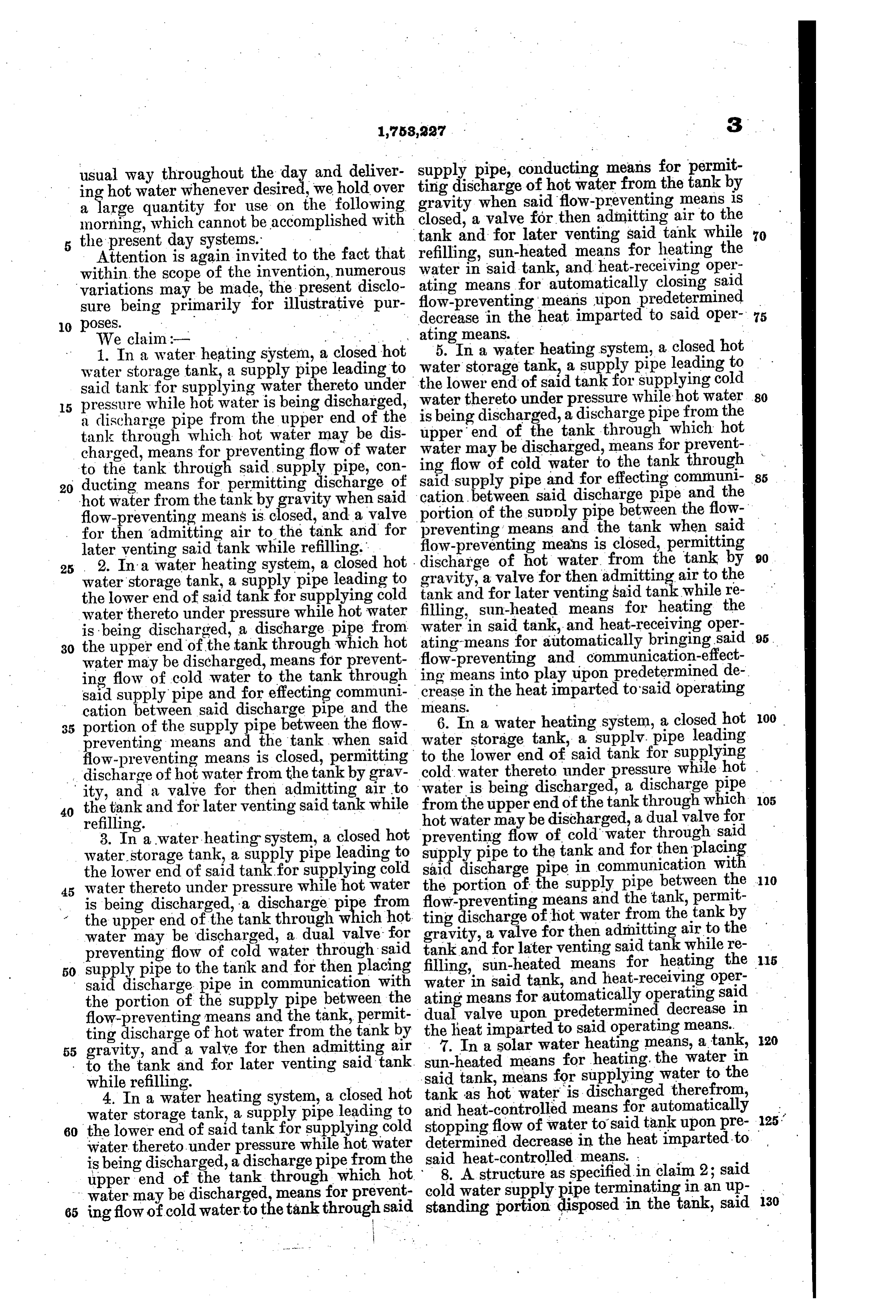
usual way throughout the day and deliver supply pipe, conducting means for permit ting discharge of hot water from the tank by ing hot water whenever desired, we hold over gravity when said flow-preventing means is a large quantity for use on the following closed, a valve for then admitting air to the morning, which cannot be accomplished with the present day systems. tank and for later venting said tank while 70 Attention is again invited to the fact that refilling, sun-heated means for heating the within the scope of the invention, numerous water in said tank, and heat-receiving oper ating means for automatically closing said variations may be made, the present disclo flow-preventing means upon predetermined sure being primarily for illustrative pur decrease in the heat imparted to said oper 75
5. In a water heating system, a closed hot 1. In a water heating system, a closed hot water water storage tank, a supply pipe leading to the storage tank, a supply pipe leading to said tank for supplying water thereto under lower end of said tankfor supplying cold 15 pressure while hot water is being discharged, water thereto under pressure while hot water 80 is being discharged, a discharge pipe from the upper end of the upper end of the tank a discharge pipe from the tank through which hot water may be dis water may be discharged,through which hot charged, means for preventing flow of water ing flow of cold water tomeans for prevent the tank through to the tank through said supply pipe, con 20 ducting means for permitting discharge of said supply pipe and for effecting communi
hot water from the tank by gravity when said cation between flow-preventing means is closed, and a valve portion said discharge pipe and the of the supply pipe between the flow preventing means and the tank when said for then admitting air to the tank and for flow-preventing later venting said tank while refilling." means is closed, permitting 90 25 . 2. In a water heating system, a closed hot discharge of hot water from the tank by water storage tank, a supply pipe leading to tankgravity, a valve for then admitting air to the the lower end of said tank for supplying cold filling,andsun-heated for later venting said tank while re means for heating the water thereto under pressure while hot water water in said tank, and heat-receiving oper is being discharged, a discharge pipe from ating means for automatically bringing said 95. 30 the upper end of the tank through which hot water may be discharged, means for prevent ing flow-preventing and communication-effect means into play upon predetermined de ing flow of cold water to the tank through said supplypipe and for effecting communi means.in the heat imparted to said operating crease cation between said discharge pipe and the 35 portion of the supply pipe between the flow 6. Instorage water a watertank, heating
system, a closed
leading preventing means an the tank when said flow-preventing means is closed, permitting to the lower end of said tank for supplying discharge of hot water from the tank by grav cold water thereto under pressure while hot . water is being discharged, a discharge pipe 105 ity, and a valve for then admitting air to from the upper end of the tank through which 40 the tank and for later venting said tank while refilling. - hot water may be discharged, a dual valve for 3. In a water heating system, a closed hot preventing flow of coldwater through said water storage tank, a supply pipe leading to supply pipe to the tank and for then placin the lower end of said tankfor supplying cold said discharge pipe in communication wit 110 45 water thereto under pressure while hot water the portion of the supply pipe between the is being discharged, a discharge pipe from flow-preventing means and the tank, permit the upper end of the tank through which hot. ting discharge of hot water from the tank by gravity, a vive for then admitting air to the water may be discharged, a dual valve for tank and for later venting said tank while re lis preventing flow of cold water through said 50 supply pipe to the tank and for then placing filling, sun-heated means for heating the said discharge pipe in communication with water means in said tank, and heat-receiving oper the portion of the supply pipe between the ating for automatically operating said dual valve upon predetermined decrease in flow-preventing means and the tank, permit the ting discharge of hot water from the tank by 7.heat imparted to said operating means. In a solar water heating means, a tank, 1so 55 gravity, and a valve for then admitting air to the tank and for later venting said tank. saidsun-heated means for heating, the Water in while refilling. tank, means for supplying water to the 4. In a water heating system, a closed hot tank as hot water is discharged therefrom, water storage tank, a supply pipe leading to and heat-controlled means for automatically 125. 60 the lower end of said tank for supplying cold stopping flow of water to said tank upon pre determined decrease in the heat imparted to water thereto under pressure while hot water said is being discharged, a discharge pipe from the heat-controlled means. . upper end of the tank through which hot cold 8. water
A structure supply aspipe specified in claimin2;ansaid
65 ing flow of cold water to t e tankthrough said standing portion disposed in the tank, said
Page 6
pipe portion having an outwardly opening check valve near the tank bottom and an in wardly opening check valve spaced above the first named check valve, said pipe portion being otherwise out of communication with the tank.
9. In a solar water heater having a water receiving tank and sun-heated water-heating means, thermostatic means for automatically stopping flow of water to said tank upon pre determined decrease in the heat imparted to said thermostatic means.
In testimony, whereof we have hereunto affixed our signatures.
FRANK J. BENTZ.
JAMES L. MASON.
Provenance
- Collection
- Cited prior art
- Original PDF
- patentimages.storage.googleapis.com →
- Filed
- 1928-08-22
- Pages
- 6
- Method
- pdftotext (the PDF's own text layer) + pdftoppm 300dpi page scans
- Source
- Google Patents bibliographic record
- Granted
- 1930-04-08
- Inventors
- Henry A Wheeler; Frank J Bentz; James L Mason; FRANK J BENTZ; L E BENTZ
- Transcribed from
- patentimages.storage.googleapis.com →