patent · US4055948
Solar thermal-radiation, absorption and conversion system
1 November 1977
Page 1 — bibliographic record
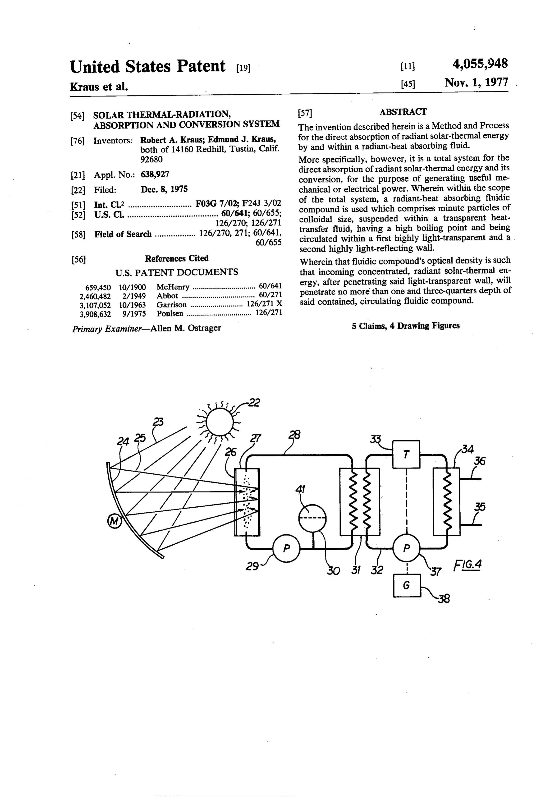
United States Patent (19) (11) 4,055,948 Kraus et al. 45 Nov. 1, 1977
(54). SOLARTHERMAL-RADIATION, 57 ABSTRACT ABSORPTION AND CONVERSION SYSTEM The invention described herein is a Method and Process (76) Inventors: Robert A. Kraus; Edmund J. Kraus, for the direct absorption of radiant solar-thermal energy both of 14160 Redhill, Tustin, Calif. by and within a radiant-heat absorbing fluid.
92680 More specifically, however, it is a total system for the (21) Appl. No.: 638,927 direct absorption of radiant solar-thermal energy and its conversion, for the purpose of generating useful me 22 Filed: Dec. 8, 1975 chanical or electrical power. Wherein within the scope 51) Int. C.? ............................ F03G 7/02; F24J 3/02 of the total system, a radiant-heat absorbing fluidic 52 U.S. Cl. ........................................ 60/641; 60/655; compound is used which comprises minute particles of 126/270; 126/271 colloidal size, suspended within a transparent heat 58) Field of Search .................. 126/270, 271; 60/641, transfer fluid, having a high boiling point and being 60/655 circulated within a first highly light-transparent and a second highly light-reflecting wall.
(56) References Cited Wherein that fluidic compound's optical density is such
659,450 10/1900 McHenry ............................... 60/641 ergy, after penetrating said light-transparent wall, will 2,460,482 2/1949 Abbot .................................... 60/271 penetrate no more than one and three-quarters depth of 3,107,052 10/1963 Garrison ..... . 126/271 X said contained, circulating fluidic compound. 3,908,632 9/1975 Poulsen ................................ 126/271
Primary Examiner-Allen M. Ostrager 5 Claims, 4 Drawing Figures
Page 2
Drawing sheet — no readable text.
Page 3
dix to complete the total concept for a system to pro
SOLARTHERMAL-RADIATION, ABSORPTION duce power.
AND CONVERSION SYSTEM The essence of our invention deals with the first con
FIELD OF THE INVENTION
version, from the sun's emission, to the heat-transfer 5 fluid's temperature rise and the means for the implemen
In its preferred embodiment, the invention herein is a tation thereof.
solar-thermal power plant, utilizing multiple arrays of The Conceptional Differences of the Prior Art sun-tracking mirror heliostats to focus incoming solar thermal radiative energy through a highly light-trans The essential differences between the devices of the parent radiation receiving fluid containment shell lo O prior art and that of our own invention are set apart by cated on top of a tall central tower, thereby causing the three different conceptional philosophies. heating of a radiant-heat absorbing fluidic compound The first crucial and essential differences come to circulated within, through only one one basic, basic light through the analysis of the basic thermodynamic thermodynamic heat transfer process; namely, that of heat-transfer processes involved to raise their respective radiation acting directly between the sun and the heat 15 system's heat-transfer fluid's temperature. transfer fluid to be heated. The second crucial and essential differences between
THE STATE OF THE PRIOR ART
the respective systems involve the physical implementa tion for the heat-transfer, from the sun's thermal emis
The state of the prior art provides a number of de sion, to the rise in temperature of the respective sys vices, or systems, designed for the collection of solar tem's heat-transfer fluid.
thermal radiant energy, most of which are based, in And, third, there is a definite difference in the kind of their construction, on flat, metallic, radiant-heat collec heat-transfer fluid used in the systems of the prior art tor plates comprising a dull-black, non-reflecting outer and that of our own invention.
surface, directly and perpendicularly exposed to the In analysis of the respective system's first crucial and sun's radiation, and comprising a series of internal fluid 25 essential differences, the devices of the prior art, be passages through which a suitable heat-transfer fluid is cause of their construction, involve all three basic ther circulated for the evacuation of the collected thermal modynamic heat-transfer processes known: energy to be used, either locally or at some remote First, the involvement of the basic heat-transfer pro location. Others are constructed of black glass, but cess of radiation, which constitutes the thermodynaic operate basically as the devices constructed from con 30 transfer link, between the sun's surface and the sun ventional materials. exposed outer surface of the system's collector plates, to The typical construction features of the devices in the raise the collector plate's outer surface temperature by prior art are only discussed briefly, particularly since means of direct radiation.
only the kind and numbers of the basic thermodynamic Second, follows the involvement of the basic heat heat-transfer processes involved, from the sun's emis 35 transfer process of conduction, which transfers the col sion of thermal radiation, to the system's heat-transfer lected thermal energy from that collector plate's un fluid's rise in temperature and the actual implementation exposed outer surface, at elevated temperature, to that thereof represent the essence between the devices of the plate's inner surface at a substantially lower tempera prior art and that of our own invention. Anyone skilled ture.
in the art of designing such devices could easily imple And, third, the involvement of the basic heat-transfer ment the same once the basic conceptional philosophy process of convection, which, in turn, transfers the of the operation for our device is established, which is thermal energy from the collector plate's inner surface the object of the patent application herein. to the heat-transfer fluid circulating within, at still The basic and essential differences in the conceptional lower temperature.
philosophy and operational procedures between the 45 Whereas, by comparison, the system of our own in devices of the prior art and that of our own invention vention involves only one basic heat-transfer process; can best be found in the difference between the kind and namely, the process of radiation, emitted by the sum, numbers of the basic thermodynamic heat-transfer pro being received directly by and within the system's heat cesses involved to accomplish the heating of the sys transfer fluid, tem's heat-transfer fluid for further conversion into 50 The advantages of a system such as that of our own useful power and in the differences in which the con invention can immediately be seen and recognized by ceptional ideas are implemented, respectively. anyone knowledgeable in the science of thermodynam The total scope of the power-producing scheme, for CS, either a device of the prior art or that of our own inven The analysis of the respective system's second crucial tion, encompasses and involves two stages of thermody 55 and essential differences show the thermal collector namic energy conversion. One deals with the conver plates of the prior art being physically constructed from sion of radiant heat, from the sun's emission, to the a non-light-transparent material since in those devices temperature rise of either system's heat-transfer fluid. only the sunexposed, dull-black, non-reflecting outer The other deals with the actual conversion of said cap surface is stricken by the incoming solar-thermal radiant tured thermal energy into useful power. energy. Whereas, in the device of our own invention, The letter the latter conversion, from the thermal the sun's incoming rays pass directly through the sys energy contained within the heat-transfer fluid to the tem's glass-like light-transparent fluid containment wall conversion into power, proceeds for both the systems of and the contained transparent heat-transfer fluid within the prior art and that of our own invention, more or less to strike the minute, non-reflecting particles of colloidal in a conventional way. 65 size, homogenously suspended within that heat-transfer Considered to be extremely inportant within the total fluid, thereby transferring that incoming thermal radi scope of the power-producing scheme, the latter con antenergy to the fluid suspended particles directly from version is conversion is mentioned herein as an appen within.
Page 4
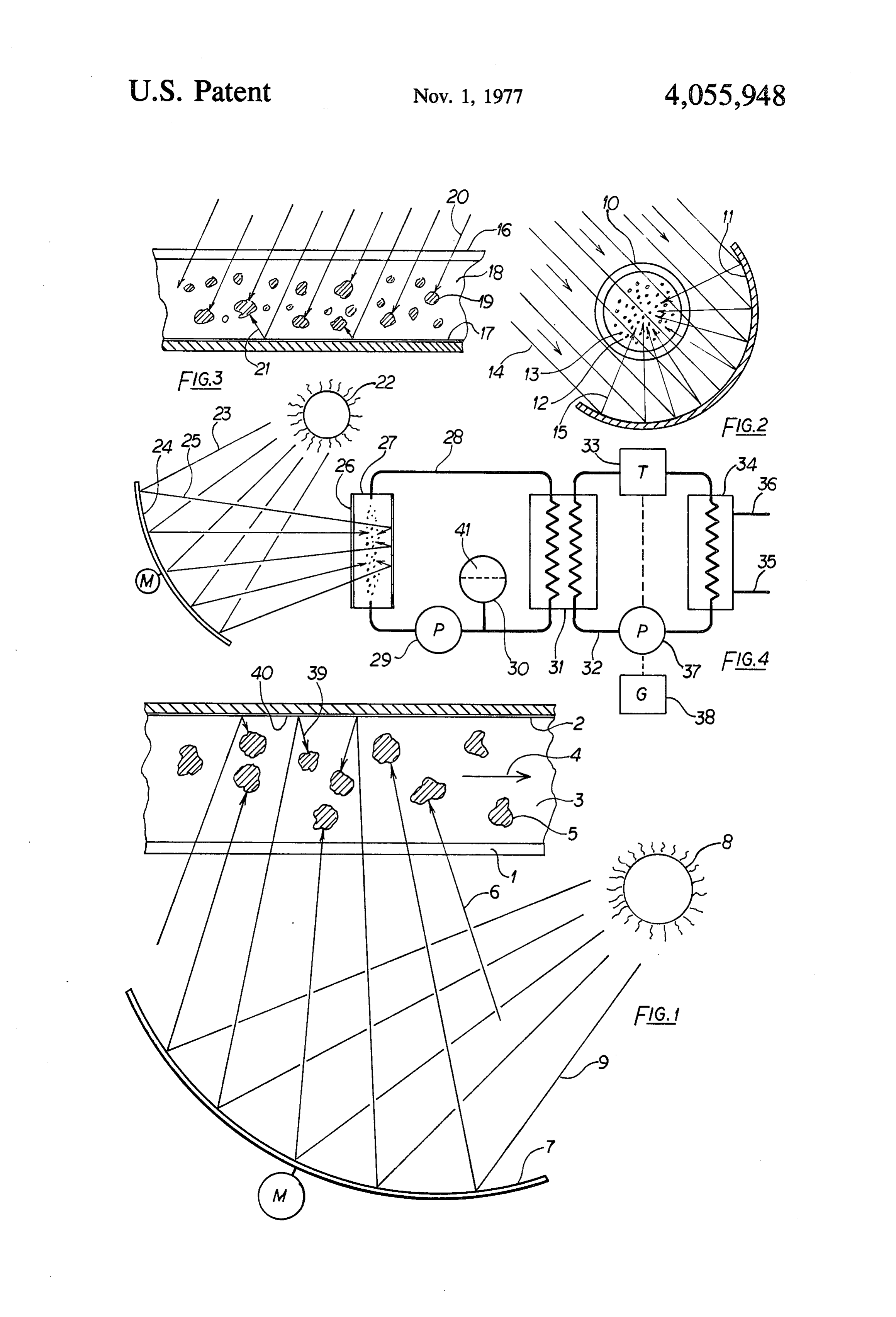
And, finally, the third crucial and essential difference FIG. 3 shows a device for the collection of direct between the two respective systems can be recognized incoming solar-thermal radiant energy through a highly in that the systems of the prior art do not specify a light-transparent fluid containment shell, or radiation definite optical density of their system's heat-transfer receiver, and partial reflection of said radiant energy fluid as being critical. In fact, the heat-transfer fluid 5 from the opposing highly light-reflecting wall and the used in the devices of the prior art could be almost any relation of the fluid's optical density to the transparent fluid, from ordinary water to certain chemical con fluid's total depth, and the absorption of reflected en pounds having a boiling point higher, or even lower, ergy by the suspended particles of colloidal size. than that of water. FIG. 4 shows a typical block diagram of the pressur Whereas, the heat-transfer fluid for the system of our 10 ized closed fluid circuit of the preferred embodiment, in own invention is formulated to conform strictly to a combination with a standard Rankin vapor power-pro specific optical density suitable for the design of the ducing plant.
transparent fluid containment shell within the total scope of a solar power-producing plant. NUMERICAL DESCRIPTION OF THE Furthermore, the heat-transfer fluid used in the sys 15 DRAWINGS tems of the prior art could be from perfectly clear to FIG. 1 shows a section of the highly light-transparent any color in the visible spectrum of light. fluid containment wall 1 of the solar-thermal receiver 2 Whereas, the heat-transfer fluid in a system of our and 3, respectively, and 2 represents the opposing own invention comprises minute, dull-black, non-light highly light-reflecting wall thereof. 3 is the transparent reflecting particles of colloidal size being suspended heat-transfer fluid circulated through the fluid contain within a clear heat-transfer fluid as a carrier media and being arranged in their quantitative magnitude so that clesment in direction of the arrow 4.5 are the minute parti of colloidal size, suspended within the transparent the sun's radiant flux can penetrate the heat-transfer heat-transfer fluid through a distance of no more than one and three transfer fluid 3.6 represents the incoming quarters fluid depth between a first highly light-trans 25 solar-thermal radiation reflected by the sun-tracking mirror heliostat 7.8 is the sun and 9 is the sun's radiation parent and a second highly light-reflecting fluid con tainment wall. not yet reflected by either one or an entire array of the mirror heliostats 7.
OBJECT OF OUR INVENTION FIG. 2 shows a cross-section perpendicular to the It is, therefore, an object of our invention to provide 30 cylinder axis of an alternate design, using a light-trans a new and novel means for the collection of vast parent boiler tube 10 suspended at the axial center of an amounts of highly concentrated solar-thermal radiant concentrically arranged half cylindrical sunlight re energy at extraordinary temperatures necessary for the flecting mirror 11 and the internally circulated heat efficient operation of modern steam turbines. transfer fluid 12, also comprising minute particles of A further object of our invention is to provide a new 35 colloidal size 13. 14 are direct incoming or heliostat and novel means to eliminate the heat-transfer time reflected radiations emitted by the sun and 15 are those through the system's fluid containment shell, which rays directed and concentrated through the transparent normally acts as a thernal insulating interface between boiler tube 10 and the circulating fluidic heat-transfer the solar-radiant energy and the contained heat-transfer compound 12.
fluid. FIG. 3 shows a perpendicular sectional view of a flat A still further object of our invention is to simplify the solar-thermal receiver, wherein 16 is the first light total system's operational concept, thereby lessening transparent containment wall. 17 represents the light the system's inherent initial construction cost. reflecting wall thereof. 18 is the transparent heat-trans And a still further object of our invention is the capa fer fluid and 19 are the minute fluid suspended particles bility to provide a vapor, power-producing plant, pref 45 of colloidal size. 20 are incoming thermal radiations erably of the Rankin type, with a vapor having the directly striking the suspended particles of colloidal size necessary high temperatures for an efficient turbine and 21 is part of the incoming solar-thermal radiation operation. reflected by that second light-reflecting wall, striking Another object is the utilization of concentrated sun these suspended particles from the opposing direction light for the inexpensive production of electrical power. to convert radiant into thermal energy within the fluidic
Still another object of our invention is to provide a fast thermal conversion rate from the highly focused compound. FIG. 4 shows a block diagram of a solar thermal and concentrated solar-thermal radiant energy to the electric power plant of our own invention, illustrating absorption of that energy from within the system's cir culating heat-transfer fluid. 55 in detail the typical components of a total scheme neces These and other objects of our invention become sary for the production of electrical power. Wherein, 22 is the sun emitting thernal radiation 23 apparent through the following detailed specifications and appended drawings. which strikes the sun-tracking mirror heliostat 24 to reflect and direct concentrated solar-thermal radiation
BRIEF DESCRIPTION OF THE DRAWING 25 through the transparent containment wall 26 of the FIG. 1 shows the basic construction of the device in solar-thermal receiver 27. Included is also a fluid circu its preferred embodiment, showing some of the solid lating loop 28 and pump 29, fluidic pressurization tank particles of colloidal size being suspended within the 30, pressurization gas 41 and the boiler heat exchanger heat-transfer fluid, illustrated as a highly magnified 31, part of which is an integral part of the connected enlargement, and incoming solar-thermal radiation 65 Rankin heat vapor power cycle 32, comprising a vapor striking these particles for the conversion of its energy. turbine 33, condenser heat exchanger 34, having a cool FIG. 2 shows an alternate embodiment of the device, ing water inlet 35 and cooling water outlet 36, the boiler also including its heat-transfer fluid. feed pump 37 and the electrical generator 38.
Page 5
particles of colloidal size within that fluid 3, so that only
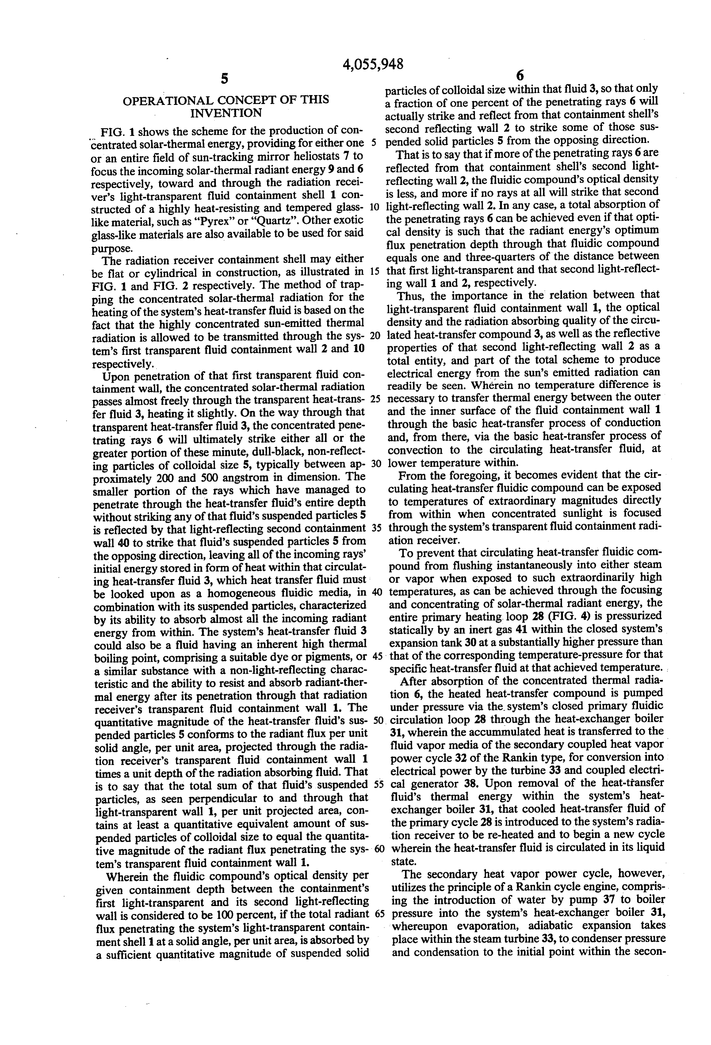
OPERATIONAL CONCEPT OF THIS a fraction of one percent of the penetrating rays 6 will INVENTION actually strike and reflect from that containment shell's FIG. 1 shows the scheme for the production of con second reflecting wall 2 to strike some of those sus centrated solar-thermal energy, providing for either one 5 pended solid particles 5 from the opposing direction. That is to say that if more of the penetrating rays 6 are or an entire field of sun-tracking mirror heliostats 7 to focus the incoming solar-thermal radiant energy 9 and 6 reflected from that containment shell's second light respectively, toward and through the radiation recei reflecting wall 2, the fluidic compound's optical density ver's light-transparent fluid containment shell 1 con is less, and more if no rays at all will strike that second structed of a highly heat-resisting and tempered glass 10 light-reflecting wall 2. In any case, a total absorption of like material, such as "Pyrex' or "Quartz'. Other exotic the penetrating rays 6 can be achieved even if that opti cal density is such that the radiant energy's optimum glass-like materials are also available to be used for said flux purpose. penetration depth through that fluidic compound The radiation receiver containment shell may either equals one and three-quarters of the distance between be flat or cylindrical in construction, as illustrated in 15 that first light-transparent and that second light-reflect FIG. 1 and FIG. 2 respectively. The method of trap ing wall 1 and 2, respectively.
Thus, the importance in the relation between that ping the concentrated solar-thermal radiation for the light-transparent heating of the system's heat-transfer fluid is based on the fluid containment wall 1, the optical fact that the highly concentrated sun-emitted thermal density and the radiation absorbing quality of the circu radiation is allowed to be transmitted through the sys 20 lated heat-transfer compound 3, as well as the reflective tem's first transparent fluid containment wall 2 and 10 properties of that second light-reflecting wall 2 as a respectively. total entity, and part of the total scheme to produce Upon penetration of that first transparent fluid con electrical energy from the sun's emitted radiation can tainment wall, the concentrated solar-thermal radiation readily be seen. Wherein no temperature difference is passes almost freely through the transparent heat-trans 25 necessary to transfer thermal energy between the outer fer fluid 3, heating it slightly. On the way through that and the inner surface of the fluid containment wall 1 transparent heat-transfer fluid 3, the concentrated pene through the basic heat-transfer process of conduction trating rays 6 will ultimately strike either all or the and, from there, via the basic heat-transfer process of greater portion of these minute, dull-black, non-reflect convection to the circulating heat-transfer fluid, at ing particles of colloidal size 5, typically between ap 30 lower temperature within.
proximately 200 and 500 angstrom in dimension. The From the foregoing, it becomes evident that the cir smaller portion of the rays which have managed to culating heat-transfer fluidic compound can be exposed penetrate through the heat-transfer fluid's entire depth to temperatures of extraordinary magnitudes directly without striking any of that fluid's suspended particles 5 from within when concentrated sunlight is focused is reflected by that light-reflecting second containment 35 through the system's transparent fluid containment radi wall 40 to strike that fluid's suspended particles 5 from ation receiver.
the opposing direction, leaving all of the incoming rays' To prevent that circulating heat-transfer fluidic com initial energy stored in form of heat within that circulat pound from flushing instantaneously into either steam ing heat-transfer fluid 3, which heat transfer fluid must or vapor when exposed to such extraordinarily high be looked upon as a homogeneous fluidic media, in temperatures, as can be achieved through the focusing combination with its suspended particles, characterized and concentrating of solar-thermal radiant energy, the by its ability to absorb almost all the incoming radiant entire primary heating loop 28 (FIG. 4) is pressurized energy from within. The system's heat-transfer fluid 3 statically by an inert gas 41 within the closed system's could also be a fluid having an inherent high thermal expansion tank 30 at a substantially higher pressure than boiling point, comprising a suitable dye or pigments, or 45 that of the corresponding temperature-pressure for that a similar substance with a non-light-reflecting charac specific heat-transfer fluid at that achieved temperature. teristic and the ability to resist and absorb radiant-ther After absorption of the concentrated thermal radia mal energy after its penetration through that radiation tion 6, the heated heat-transfer compound is pumped receiver's transparent fluid containment wall 1. The under pressure via the system's closed primary fluidic quantitative magnitude of the heat-transfer fluid's sus 50 circulation loop 28 through the heat-exchanger boiler pended particles 5 conforms to the radiant flux per unit 31, wherein the accummulated heat is transferred to the solid angle, per unit area, projected through the radia fluid vapor media of the secondary coupled heat vapor tion receiver's transparent fluid containment wall 1 power cycle 32 of the Rankin type, for conversion into times a unit depth of the radiation absorbing fluid. That electrical power by the turbine 33 and coupled electri is to say that the total sum of that fluid's suspended 55 cal generator 38. Upon removal of the heat-transfer particles, as seen perpendicular to and through that fluid's thermal energy within the system's heat light-transparent wall 1, per unit projected area, con exchanger boiler 31, that cooled heat-transfer fluid of tains at least a quantitative equivalent amount of sus the primary cycle 28 is introduced to the system's radia pended particles of colloidal size to equal the quantita tion receiver to be re-heated and to begin a new cycle tive magnitude of the radiant flux penetrating the sys 60 wherein the heat-transfer fluid is circulated in its liquid tem's transparent fluid containment wall 1. State.
Wherein the fluidic compound's optical density per The secondary heat vapor power cycle, however, given containment depth between the containment's utilizes the principle of a Rankin cycle engine, compris first light-transparent and its second light-reflecting ing the introduction of water by pump 37 to boiler wall is considered to be 100 percent, if the total radiant 65 pressure into the system's heat-exchanger boiler 31, flux penetrating the system's light-transparent contain whereupon evaporation, adiabatic expansion takes ment shell 1 at a solid angle, per unit area, is absorbed by place within the steam turbine 33, to condenser pressure a sufficient quantitative magnitude of suspended solid and condensation to the initial point within the secon
Page 6
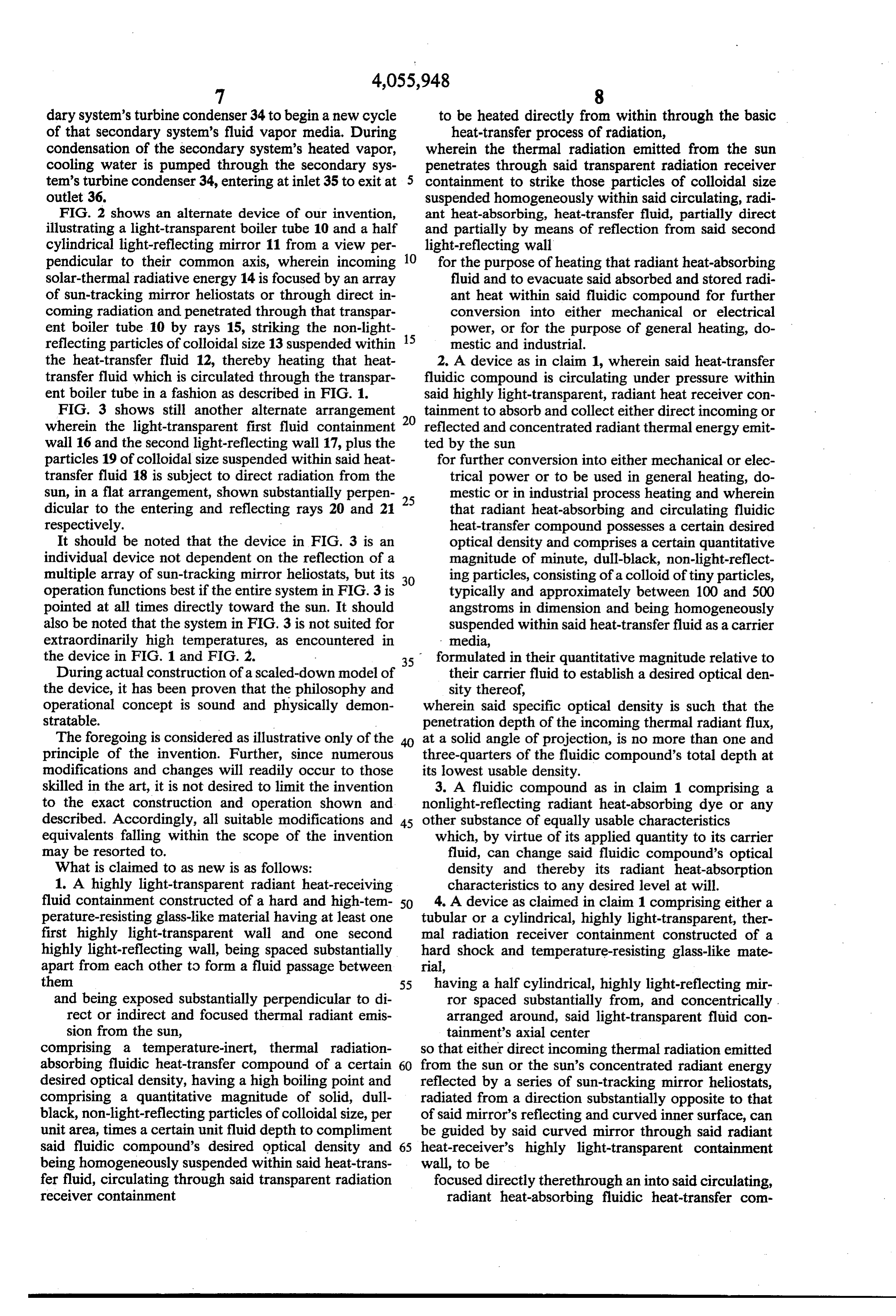
dary system's turbine condenser 34 to begin a new cycle to be heated directly from within through the basic of that secondary system's fluid vapor media. During heat-transfer process of radiation, condensation of the secondary system's heated vapor, wherein the thermal radiation emitted from the sun cooling water is pumped through the secondary sys penetrates through said transparent radiation receiver tem's turbine condenser 34, entering at inlet 35 to exit at 5 containment to strike those particles of colloidal size outlet 36. suspended homogeneously within said circulating, radi FIG. 2 shows an alternate device of our invention, ant heat-absorbing, heat-transfer fluid, partially direct illustrating a light-transparent boiler tube 10 and a half and partially by means of reflection from said second cylindrical light-reflecting mirror 11 from a view per light-reflecting wall pendicular to their common axis, wherein incoming 10 for the purpose of heating that radiant heat-absorbing solar-thermal radiative energy 14 is focused by an array fluid and to evacuate said absorbed and stored radi of sun-tracking mirror heliostats or through direct in ant heat within said fluidic compound for further coming radiation and penetrated through that transpar conversion into either mechanical or electrical ent boiler tube 10 by rays 15, striking the non-light 15 power, or for the purpose of general heating, do reflecting particles of colloidal size 13 suspended within mestic and industrial.
the heat-transfer fluid 12, thereby heating that heat 2. A device as in claim 1, wherein said heat-transfer transfer fluid which is circulated through the transpar fluidic compound is circulating under pressure within ent boiler tube in a fashion as described in FIG. 1. said highly light-transparent, radiant heat receiver con FIG. 3 shows still another alternate arrangement 20 tainment to absorb and collect either direct incoming or wherein the light-transparent first fluid containment reflected and concentrated radiant thermal energy emit wall 16 and the second light-reflecting wall 17, plus the ted by the sun particles 19 of colloidal size suspended within said heat for further conversion into either mechanical or elec transfer fluid 18 is subject to direct radiation from the trical power or to be used in general heating, do sun, in a flat arrangement, shown substantially perpen 25 mestic or in industrial process heating and wherein dicular to the entering and reflecting rays 20 and 21 that radiant heat-absorbing and circulating fluidic respectively. heat-transfer compound possesses a certain desired It should be noted that the device in FIG. 3 is an optical density and comprises a certain quantitative individual device not dependent on the reflection of a magnitude of minute, dull-black, non-light-reflect multiple array of sun-tracking mirror heliostats, but its 30 ing particles, consisting of a colloid of tiny particles, operation functions best if the entire system in FIG. 3 is typically and approximately between 100 and 500 pointed at all times directly toward the sun. It should angstroms in dimension and being homogeneously also be noted that the system in FIG. 3 is not suited for suspended within said heat-transfer fluid as a carrier extraordinarily high temperatures, as encountered in media, the device in FIG. 1 and FIG. 2. formulated in their quantitative magnitude relative to During actual construction of a scaled-down model of their carrier fluid to establish a desired optical den the device, it has been proven that the philosophy and sity thereof, operational concept is sound and physically demon wherein said specific optical density is such that the stratable. penetration depth of the incoming thermal radiant flux, The foregoing is considered as illustrative only of the 40 at a solid angle of projection, is no more than one and principle of the invention. Further, since numerous three-quarters of the fluidic compound's total depth at modifications and changes will readily occur to those its lowest usable density.
skilled in the art, it is not desired to limit the invention 3. A fluidic compound as in claim 1 comprising a to the exact construction and operation shown and nonlight-reflecting radiant heat-absorbing dye or any described. Accordingly, all suitable modifications and 45 other substance of equally usable characteristics equivalents falling within the scope of the invention which, by virtue of its applied quantity to its carrier may be resorted to. fluid, can change said fluidic compound's optical What is claimed to as new is as follows: density and thereby its radiant heat-absorption 1. A highly light-transparent radiant heat-receiving characteristics to any desired level at will. fluid containment constructed of a hard and high-tem 50 4. A device as claimed in claim 1 comprising either a perature-resisting glass-like material having at least one tubular or a cylindrical, highly light-transparent, ther first highly light-transparent wall and one second mal radiation receiver containment constructed of a highly light-reflecting wall, being spaced substantially hard shock and temperature-resisting glass-like mate apart from each other to form a fluid passage between rial, them 55 having a half cylindrical, highly light-reflecting mir and being exposed substantially perpendicular to di ror spaced substantially from, and concentrically . rect or indirect and focused thermal radiant emis arranged around, said light-transparent fluid con sion from the sun, tainment's axial center comprising a temperature-inert, thermal radiation so that either direct incoming thermal radiation emitted absorbing fluidic heat-transfer compound of a certain 60 from the sun or the sun's concentrated radiant energy desired optical density, having a high boiling point and reflected by a series of sun-tracking mirror heliostats, comprising a quantitative magnitude of solid, dull radiated from a direction substantially opposite to that black, non-light-reflecting particles of colloidal size, per of said mirror's reflecting and curved inner surface, can unit area, times a certain unit fluid depth to compliment be guided by said curved mirror through said radiant said fluidic compound's desired optical density and 65 heat-receiver's highly light-transparent containment being homogeneously suspended within said heat-trans wall, to be fer fluid, circulating through said transparent radiation focused directly therethrough an into said circulating, receiver containment radiant heat-absorbing fluidic heat-transfer com
Page 7
pound, to be heated directly from within by the boiler heat-exchanger having at least one separate and basic heat-transfer process of radiation; independent fluid inlet and one separate and indepen wherein the radiant heat-absorbing heat-transfer fluidic dent fluid or vapor outlet, and a fluid pressurization compound circulating therethrough is pressurized and tank within said circulation system possesses a definite desired optical density which is for the purpose of transferring the absorbed and formulated so that the incoming radiant flux penetration stored radiant energy within that fluidic thermal through said fluidic radiant heat-absorbing compound is radiation-absorbing compound from the primary not greater than one inside diameter of either said tubu system's closed circulation system, via the included lar or said cylindrical highly light-transparent fluid boiler heat-exchanger, to a secondary closed fluid containment. 10 vapor power cycle of the Rankin type for further 5. A device as claimed in claim.1 wherein the thermal conversion into either mechanical or electrical radiant energy absorbed and stored within said radiant power, heat-absorbing fluidic heat-transfer compound is evacu and wherein, said secondary closed heat vapor power ated from the highly light-transparent, thermal radia cycle of the Rankin type comprises a composite steam tion receiver; fluid containment by said fluidic heat 15 plant cycle comprising the introduction of water by transfer compound pump to boiler pressure within that boiler heat circulated, pressurized, through a primary closed exchanger, evaporation, adiabatic expansion to con fluid circulation system denser pressure within a steam turbine expander to wherein that primary closed circulation system com produce power and condensation within a condenser to prises a circulating pump, said highly light-transparent 20 initial state. k k l k is thermal radiant energy-absorbing fluid containment, a
Provenance
- Collection
- Cited prior art
- Original PDF
- patentimages.storage.googleapis.com →
- Filed
- 1975-12-08
- Pages
- 7
- Method
- pdftotext (the PDF's own text layer) + pdftoppm 300dpi page scans
- Source
- Google Patents bibliographic record
- Granted
- 1977-11-01
- Inventors
- Robert A. Kraus; Edmund J. Kraus
- Transcribed from
- patentimages.storage.googleapis.com →