patent · US4292959
Solar energy collection system
6 October 1981
Page 1 — bibliographic record
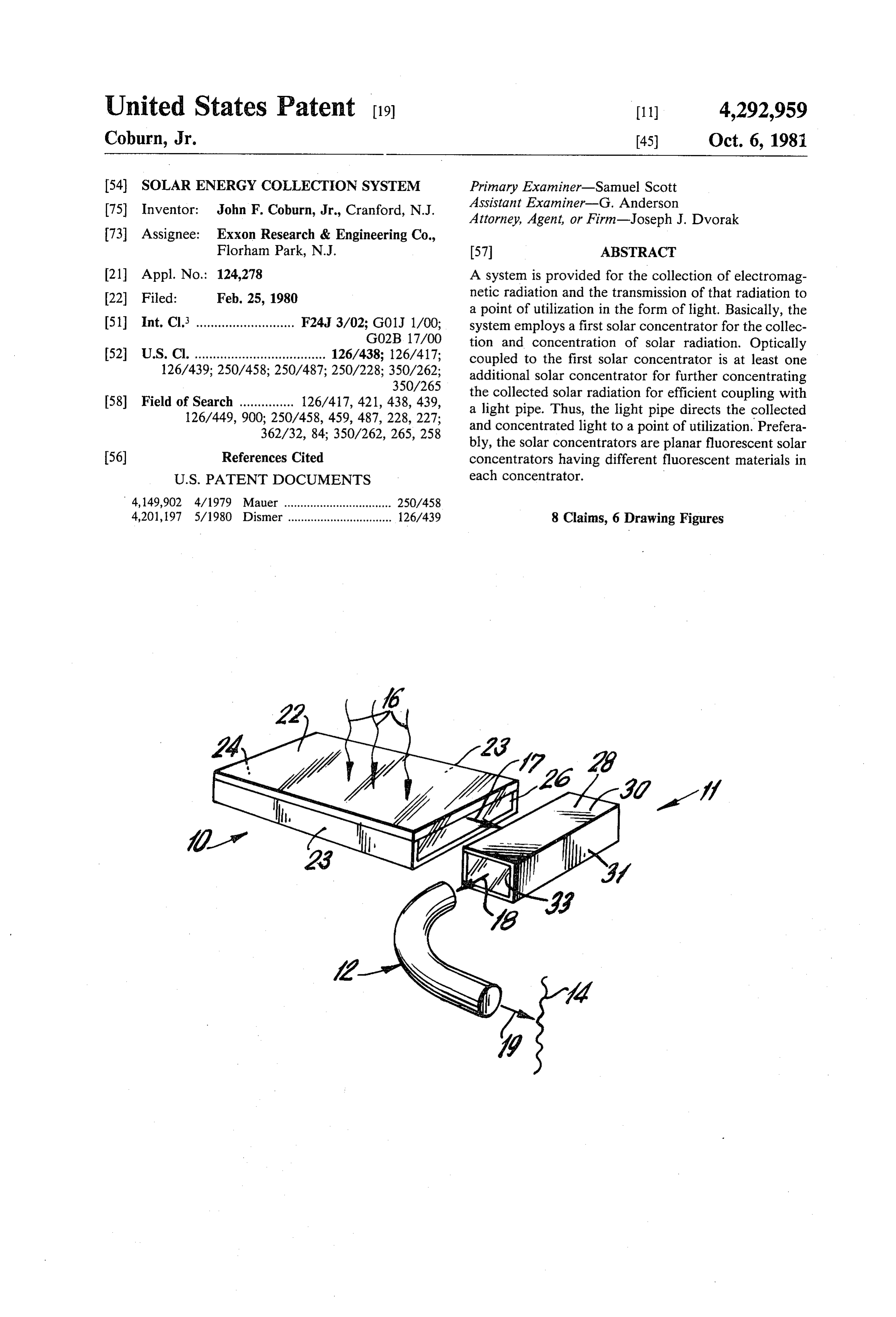
United States Patent (19) 11) 4,292,959 Coburn, Jr. 45) Oct. 6, 1981 54) SOLAR ENERGY COLLECTION SYSTEM Primary Examiner-Samuel Scott Assistant Examiner-G. Anderson (75) Inventor: John F. Coburn, Jr., Cranford, N.J. Attorney, Agent, or Firm-Joseph J. Dvorak 73 Assignee: Exxon Research & Engineering Co.,
Florham Park, N.J. 57 ABSTRACT (21) Appl. No.: 124,278 A system is provided for the collection of electromag 22 Filed: Feb. 25, 1980 netic radiation and the transmission of that radiation to a point of utilization in the form of light. Basically, the 51 Int. Cl. ........................... F24J 3/02; G01J 1/00; system employs a first solar concentrator for the collec GO2B 17/00 tion and concentration of solar radiation. Optically 52 U.S. C. .................................... 126/438; 126/417; coupled to the first solar concentrator is at least one 126/439; 250/458; 250/487; 250/228; 350/262; additional solar concentrator for further concentrating 350/265 the collected solar radiation for efficient coupling with 58) Field of Search ............... 126/417,421, 438, 439, a light pipe. Thus, the light pipe directs the collected 126/449,900; 250/458, 459, 487, 228, 227; and concentrated light to a point of utilization. Prefera 362/32, 84; 350/262, 265, 258 bly, the solar concentrators are planar fluorescent solar 56) References Cited concentrators having different fluorescent materials in
4,149,902 4/1979 Mauer ................................. 250/458 4,201,197 5/1980 Dismer ................................ 126/439 8 Claims, 6 Drawing Figures
Page 2
Drawing sheet — no readable text.
Page 3
lowing detailed description when read in light of the
SOLAR ENERGY COLLECTION SYSTEM accompanying drawings.
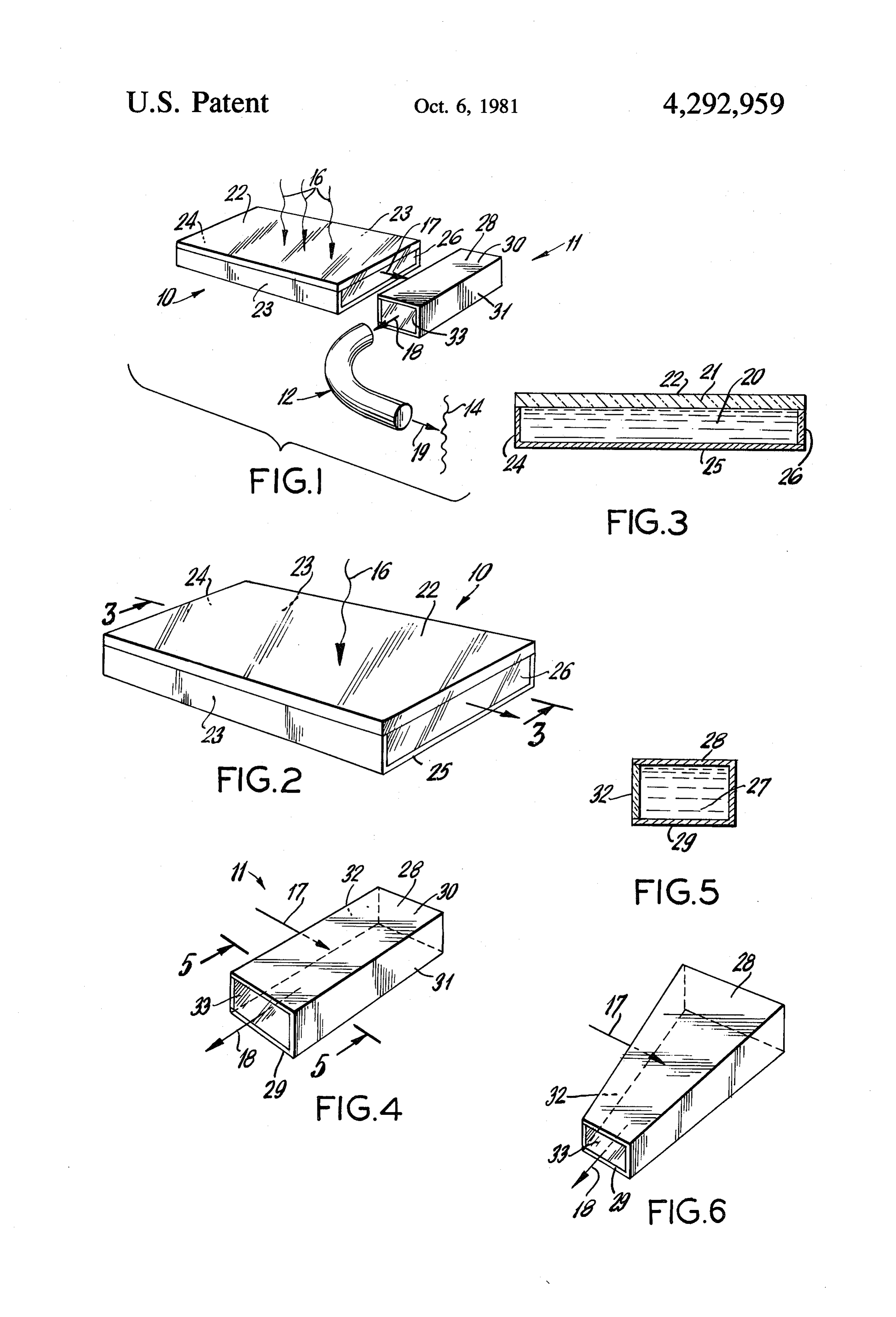
FIELD OF THE INVENTION DESCRIPTION OF THE DRAWINGS
This invention relates to a system for collecting solar 5 FIG. 1 is a schematic isometric drawing of one em energy, concentrating it and transmitting it to a point of bodiment of the present invention. use in the form of light. FIG. 2 is a schematic illustration of a fluorescent planar concentrator useful in the solar system of the
BACKGROUND OF THE INVENTION present invention.
Commercially available solar collectors typically 10 FIG. 3 is a sectional view taken along lines 3-3 of convert solar radiation incident on a generally wide FIG, 2.
area to electrical or thermal energy which is subse FIG. 4 is a schematic illustration of one connector quently transported in the converted form to a point of device used in the system of the present invention. use. Because of some of the inherent practical and tech 15 FIG. 5 is a sectional view taken along lines 5-5 of nical limitations of large area solar conversion devices, FIG. 4.
attempts have been made to concentrate the solar radia FIG. 6 is a schematic illustration of yet another con tion impinging over a wider area and focusing it onto a nector device used in the practice of the present inven smaller area conversion device. Among the typical tion.
solar energy concentrators employed are mirrors, lenses and fluorescent devices. 20 DETAILED DESCRIPTION OF THE In U.S. Pat. No. 668,404, use of a mirror for focusing INVENTION solar radiation onto a point of use is disclosed. A more Turning now to FIG. 1, the system for the collection recent solar concentrator based on the use of reflecting of solar radiation and its transmission to a point of utili solar radiation with mirrors and focusing it at a collec 25 zation according to the present invention includes a tion point is disclosed in U.S. Pat. No. 4,130,109. Since solar energy receiver 10 optically coupled to means 11 the relative position of the sun and earth changes with time, there are certain practical limitations with respect for and further concentrating the collected solar radiation transmitting it to a light transmission pipe 12 for to using mirrored surfaces for focusing solar radiation at transmission to a point of use designated generally as 14. a point of use.
In U.S. Pat. No. 4,148,300 and U.S. Pat. No. 30 lineIn16operation, incident solar radiation designated by is received in the collector 10 and concentrated 4,114,592, lens type devices are disclosed for focusing and transmitted as shown by line 17 to the second stage solar radiation on a point of use. As undoubtedly will be concentrator 11 where the light is further concentrated appreciated, high quality lenses for such applications and transmitted as shown by line 18 to light pipe 12. The are expensive and consequently are not suitable to ex light emanating from light pipe 12 and shown generally tremely widespread use. 35
In U.S. Pat. No. 4,175,980 and U.S. Pat. No. as line 19 is delivered to a point of utilization 14. 4,149,902, there are described different types of fluores Basically, the solar energy receiver 10 can be any one cent concentrators in which solar radiation is collected of the known devices for the reception of incident solar over large flat areas and focused onto a smaller area for radiation and its concentration such as planar concen the photovoltaic conversion of the focused radiant en 40 trators, mirrored reflectors, parabolic troughs, and the ergy by means of a photovoltaic device. Indeed, in U.S. like. In the practice of the present invention, however, Pat. No. 4,149,902, the photovoltaic device is contigu it is particularly preferred that the solar collector 10 be ous with the fluorescent collector. In one embodiment a fluorescent planar concentrator. These fluorescent of U.S. Pat. No. 4,175,980, however, the photovoltaic planar concentrators are known in the art. They consist, device is not contiguous with the fluorescent concentra 45 for example, of layers of dyes on light transparent slabs tor but is separated from the concentrator by means of of material or consist of glass containing fluorescent a fiber optic mechanism. In the former patent, however, chelates, certain inorganic ions and the like. Thus, as is the amount of light utilized is limited by the cross-sec shown in FIG. 3, for example, solar collector 10 consists tional area of the solar cell and, in the latter patent, the of a layer of fluorescent material 20 which is optically amount of light utilized is limited by the cross-sectional 50 coupled to a sheet of highly light transparent material area of the fiber optic mechanism. 21 such as glass or plastic. Thus, the collector 10 has a
SUMMARY OF THE INVENTION
major surface 22 for the reception of incident solar radiation. The side walls 23 and end wall 24 are prefera
According to this invention, there is provided a sys bly coated with a light reflecting material, such as alu ten for the collection of electromagnetic radiation and 55 minum, silver and the like. Also, bottom surface 25 is the transmission of that radiation to a point of utilization coated with a light diffusive material such as white paint in the form of light. Basically, the system employs a first and, preferably, a light reflective material. Thus, as can solar concentrator for the collection and concentration be seen in FIGS. 1 and 2, the incident solar radiation 16 of solar radiation. Optically coupled to the first solar is internally reflected by means of the mirrors on light concentrator is at least one additional solar concentra 60 reflective surfaces and the fluorescent material 20 and is tor for further concentrating the collected solar radia redirected so as to exit the collector at unmirrored end tion for efficient coupling with a light pipe. Thus, the wall 26.
light pipe directs the collected and concentrated light to As can be seen in FIG. 1, optically connected to end a point of utilization. Preferably, the solar concentrators wall 26 of solar collector 10 is connector means 11 for are planar fluorescent solar concentrators having differ 65 optically connecting the first stage concentrator to a ent fluorescent materials in each concentrator. light pipe. The connector 11 also further concentrates The precise characteristics and features of the inven the solar radiation as well as serves to transmit it to the tion will become more readily apparent from the fol light pipe 12. Basically, the connector means 11 for
Page 4
further concentrating the solar radiation is a second 1. A system for the collection of solar radiation and stage concentrator which may be based upon reflectors, the transmission thereof to a point of utilization in the parabolic troughs and the like, but preferably the sec form of light comprising:
ond stage solar concentrator is a fluorescent planar a solar collector for the receipt and concentration of concentrator (see FIGS. 4 and 5) consisting largely of a solar radiation, said solar collector being a planar fluorescent material 27 having light reflective surfaces fluorescent concentrator having a major surface on the top and bottom 28 and 29 of the concentrator, for receipt of instant solar radiation and an edge for transmission of the solar radiation collected and respectively, as well as end wall 30 and side wall 31. concentrated by said collector; The fluorescent material of the second stage concentra 10 second concentrator means optically coupled to said tor, of course, must be a different fluorescent material edge of said collector for receipt of concentrated from the fluorescent material in the first fluorescent solar radiation from said collector and for the fur concentrator, i.e., it must absorb solar radiation in a ther concentration of said solar radiation; different region of the spectrum. Both concentrators a light transmission pipe optically connected to said may employ dyes, chelates or inorganic ions, however. 15 second concentrator, whereby light from the col Returning to FIGS. 1 and 4, connector means 11 has lector which is concentrated in the second concen a side wall 32 which is adapted to be optically coupled 'trator is introduced into said light transmission pipe to the edge of collector concentrator 10 for the recep for transmission to a point of use; and, a utilization device remote from said solar collector tion of solar radiation from collector 10 for further 20 whereby solar radiation incident on said collector concentration in connector 11. The connector or sec is transmitted to said point of utilization in the form ond stage concentrator additionally has an unmirrored of light.
side wall 33 for optical coupling to a light transmission 2. The system of claim 1, wherein the connector is a pipe 12. planar fluorescent concentrator in which the fluores . In the embodiment shown in FIG. 6, the second stage 25 cent material is different from the fluorescent material concentrator has a geometry designed to enhance the in the collector.
concentration being achieved via the fluorescent mech 3. The device of claim 2, wherein the light pipe com anism thereby further reducing the area for light to be prises a plurality of optical waveguides, emitted-from for coupling to the light pipe 12. 4. The device of claim 3, wherein the point of utiliza 30 tion comprises a photovoltaic device.
As will be appreciated, the light transmission pipe 12 5. The device of claim 3, wherein the utilization de or optical waveguide is one which is normally em vice includes a heat exchange surface for conversion of ployed in conventional fiber optic techniques and, in the light incident on that surface to thermal energy. deed, would typically be a plurality of such fibers. 6. A solar energy system comprising: However, a single conventional light pipe may be used 35 a first planar fluorescent solar concentrator, said pla in the practice of the present invention. nar concentrator having a major surface for collec As is indicated in FIG. 1, 14 represents a point of tion and concentration of incident solar radiation, utilization. As will be readily appreciated, the light said concentrator having an end edge for transmis emanating from light pipe 12 and shown as line 19 can sion of said collected solar radiation; be projected onto a photoresponsive device such as a 40 a second planar fluorescent solar concentrator opti photovoltaic cell for direct conversion of the light inci cally coupled to said first planar concentrator for dent on the cell to electrical energy. Optionally and receipt of solar radiation transmitted by said first preferably, the point of utilization will include a heat concentrator, said second planar fluorescent con exchanger having a selective surface thereon for con 45 centrator having an end edge for transmission of said solar radiation;
verting fluid in heat exchange relationship with the heat a light transmission pipe optically coupled to said exchanger to thermal energy. second planar concentrator for receipt of solar As will be readily appreciated, control means (not radiation and transmission thereof to a point of use; shown) can be employed to switch the light at the point and, of use so as to limit the amount of thermal energy gener 50 a utilization device remote from said first and second ated in the thermal conversion device or the tempera collectors whereby solar radiation incident on said ture reached when power is not required. point of utilization in the form of light. The invention has been described in detail with par vice The 7. device of claim 6, wherein the utilization de includes a heat exchange surface for conversion of ticular reference to preferred embodiments thereof, but 55 light on that surface to thermal energy. it will be understood that reasonable variations and 8. The device of claim 6, wherein the utilization de modifications are possible without departing from the vice includes a photoresponsive surface for the conver spirit and scope of the invention. sion of light to electrical energy. What is claimed is: k .. k is a k
Page 5
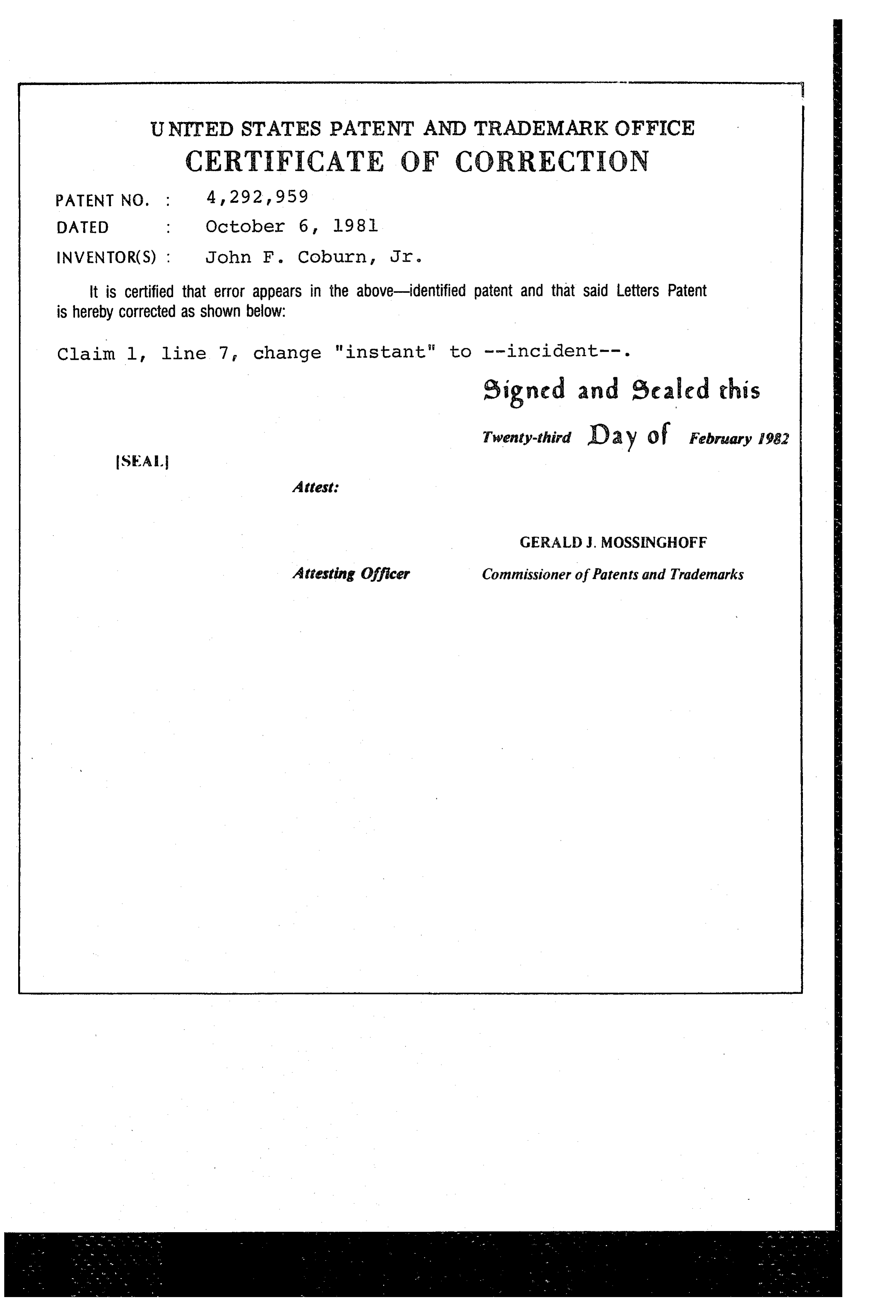
UNITED STATES PATENT AND TRADEMARK OFFICE
CERTIFICATE OF CORRECTION
NVENTOR(S) : John F. Coburn, Jr. it is certified that error appears in the above-identified patent and that said Letters Patent is hereby corrected as shown below:
Claim l, line 7 change "instant" to --incident--. signed and escaled this
Twenty-third Day of February 1982
SEAL
Attest:
GERALD . MOSSINGHOFF
attesting Officer Commissioner of Patents and Trademarks
Page 6
UNITED STATES PATENT AND TRADEMARK OFFICE
CERTIFICATE OF CORRECTION
NVENTOR(S) : John F. Coburn, Jr. It is certified that error appears in the above-identified patent and that Said Letters Patent is hereby corrected as shown below:
O Claim 1, line 7, change "instant" to --incident. signed and escaled this
Twenty-third O 2 y of February 1982
SEA.
Attest
GERALD J MOSSINGHOFF
Attesting Officer Commissioner of Patents and Trademarks
Provenance
- Collection
- Cited prior art
- Original PDF
- patentimages.storage.googleapis.com →
- Filed
- 1980-02-25
- Pages
- 6
- Method
- pdftotext (the PDF's own text layer) + pdftoppm 300dpi page scans
- Source
- Google Patents bibliographic record
- Granted
- 1981-10-06
- Inventors
- John F. Coburn, Jr.; Exxon Research and Engineering Co
- Transcribed from
- patentimages.storage.googleapis.com →