patent · US4149902
Fluorescent solar energy concentrator
17 April 1979
Page 1 — bibliographic record
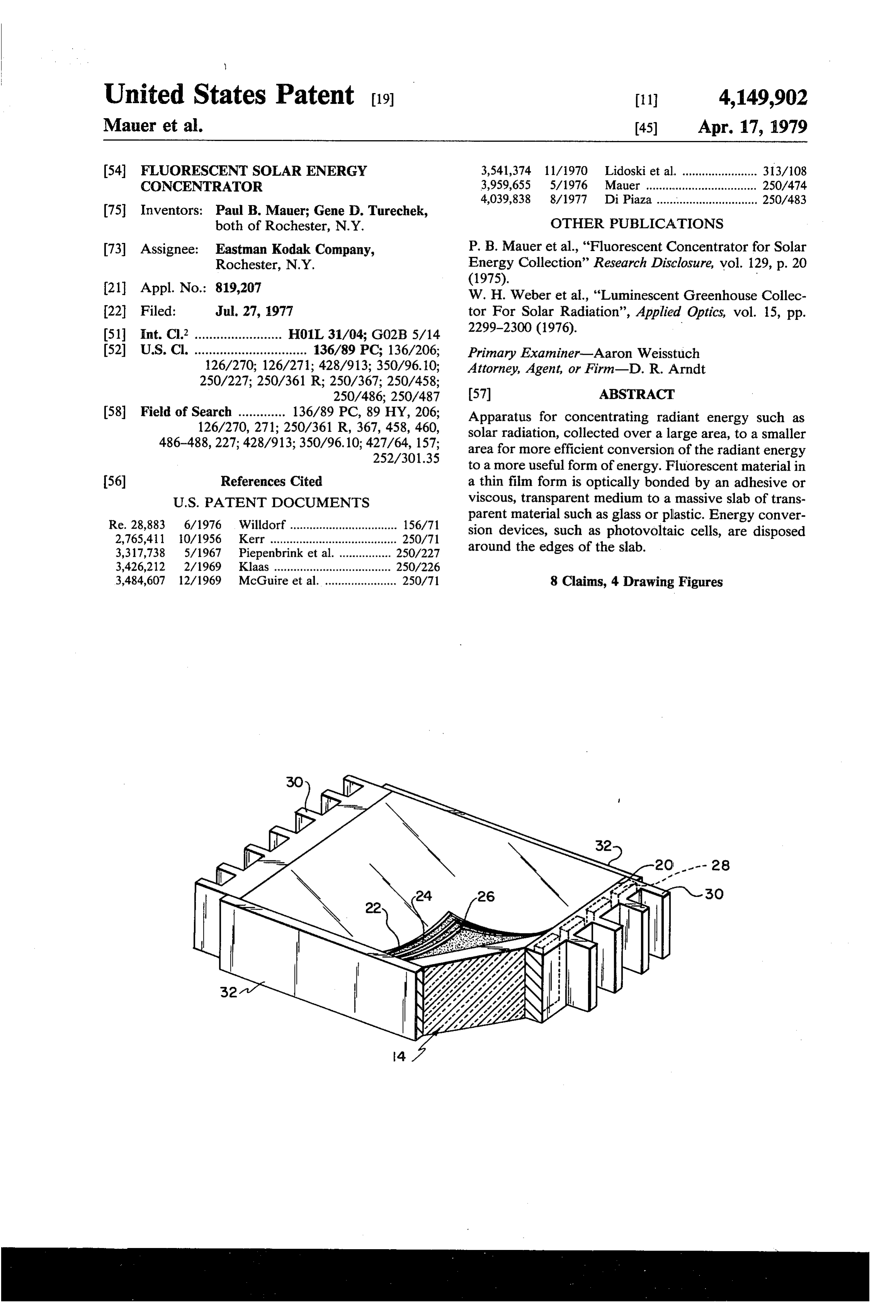
United States Patent (19) 11 4,149,902 Mauer et al. 45) Apr. 17, 1979 54 FLUORESCENT SOLAR ENERGY 3,541,374 11/1970 Lidoski et al. ....................... 313/108 CONCENTRATOR 3,959,655 5/1976 Mauer .................................. 250/474 4,039,838 8/1977 Di Piaza ............................... 250/483 75 Inventors: Paul B. Mauer; Gene D. Turechek, both of Rochester, N.Y. OTHER PUBLICATIONS 73) Assignee: Eastman Kodak Company, P. B. Mauer et al., "Fluorescent Concentrator for Solar Rochester, N.Y. Energy Collection' Research Disclosure, vol. 129, p. 20 21 Appl. No.: 819,207 (1975).
W. H. Weber et al., "Luminescent Greenhouse Collec 22 Filed: Jul. 27, 1977 tor For Solar Radiation', Applied Optics, vol. 15, pp. (51) Int. Cl. ........................ H01L 31/04; G02B 5/14 2299-2300 (1976).
(52) U.S. Cl. ............................... 136/89 PC; 136/206; Primary Examiner-Aaron Weisstuch 126/270; 126/271; 428/913; 350/96.10; Attorney, Agent, or Firm-D. R. Arndt
250/486; 250/487 (57) ABSTRACT 58 Field of Search ............. 136/89 PC, 89 HY, 206; Apparatus for concentrating radiant energy such as 126/270, 271; 250/361 R, 367, 458, 460, solar radiation, collected over a large area, to a smaller 486-488,227; 428/913; 350/96.10; 427/64, 157; area for more efficient conversion of the radiant energy
to a more useful form of energy. Fluorescent material in 56) References Cited a thin film form is optically bonded by an adhesive or
Re. 28,883 6/1976 Willdorf................................. 156/71 parent material such as glass or plastic. Energy conver 2,765,411 10/1956 Kerr ....................... ... 250/71 sion devices, such as photovoltaic cells, are disposed 3,317,738 5/1967 Piepenbrink et al. .. ... 250/227 around the edges of the slab. 3,426,212 2/1969 Klaas...................... ... 250/226 3,484,607 12/1969 McGuire et al. ...................... 250/71 8 Claims, 4 Drawing Figures
Page 2
Drawing sheet — no readable text.
Page 3
of fluorescent material may be a coating of organic dye
FLUORESCENT SOLAR ENERGY with polymer binder on a transparent plastic substrate. CONCENTRATOR Disposed around the edges of the slab in optical contact BACKGROUND OF THE INVENTION therewith are arrays of energy converters such as pho tovoltaic cells.
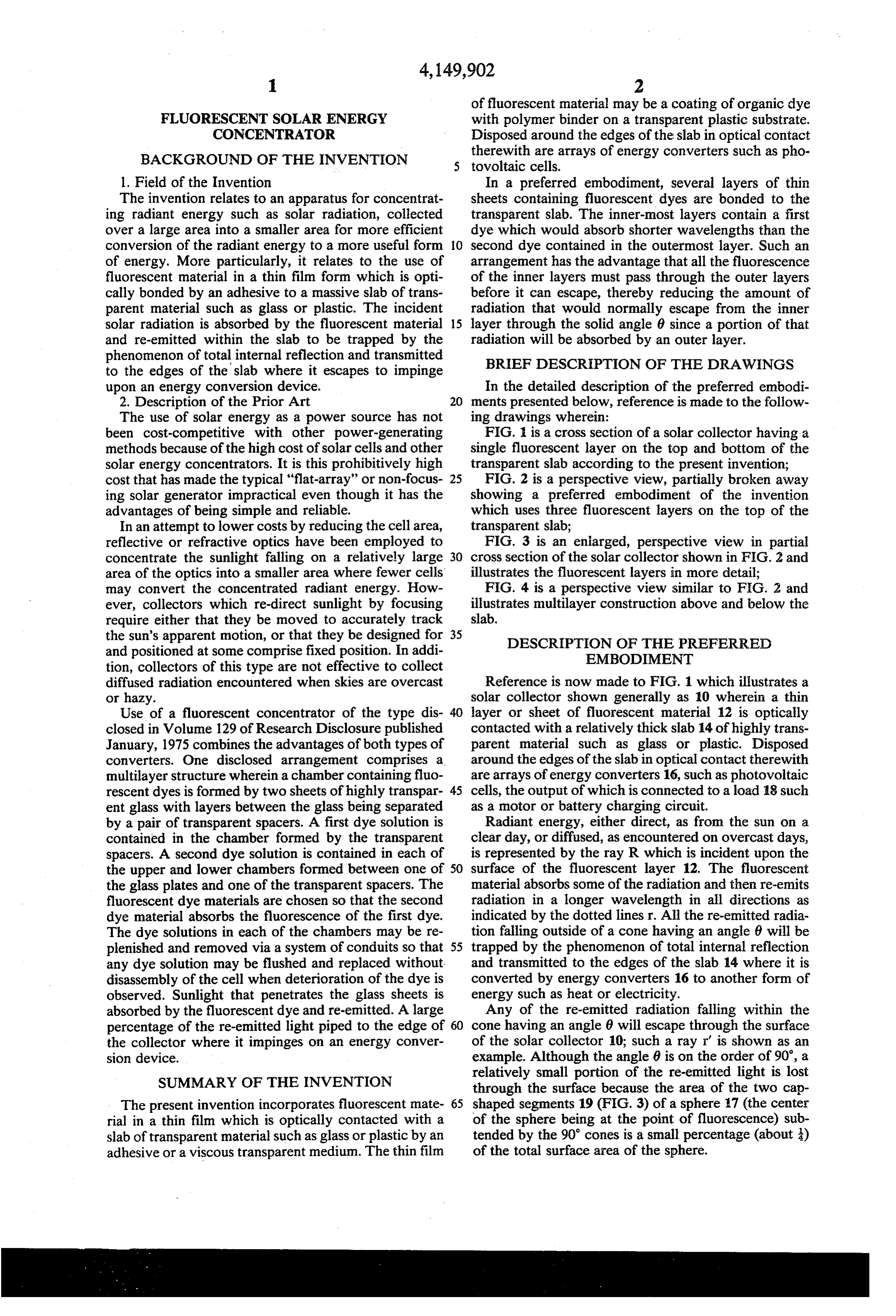
1. Field of the Invention In a preferred embodiment, several layers of thin The invention relates to an apparatus for concentrat sheets containing fluorescent dyes are bonded to the ing radiant energy such as solar radiation, collected transparent slab. The inner-most layers contain a first over a large area into a smaller area for more efficient dye which would absorb shorter wavelengths than the conversion of the radiant energy to a more useful form 10 second dye contained in the outlermost layer. Such an of energy. More particularly, it relates to the use of arrangement has the advantage that all the fluorescence fluorescent material in a thin film form which is opti of the inner layers must pass through the outer layers cally bonded by an adhesive to a massive slab of trans before it can escape, thereby reducing the amount of parent material such as glass or plastic. The incident radiation that would normally escape from the inner solar radiation is absorbed by the fluorescent material 15 layer through the solid angle 6 since a portion of that and re-emitted within the slab to be trapped by the radiation will be absorbed by an outer layer. phenomenon of total internal reflection and transmitted BRIEF DESCRIPTION OF THE DRAWINGS to the edges of the slab where it escapes to impinge upon an energy conversion device. In the detailed description of the preferred embodi 2. Description of the Prior Art 20 ments presented below, reference is made to the follow The use of solar energy as a power source has not ing drawings wherein:
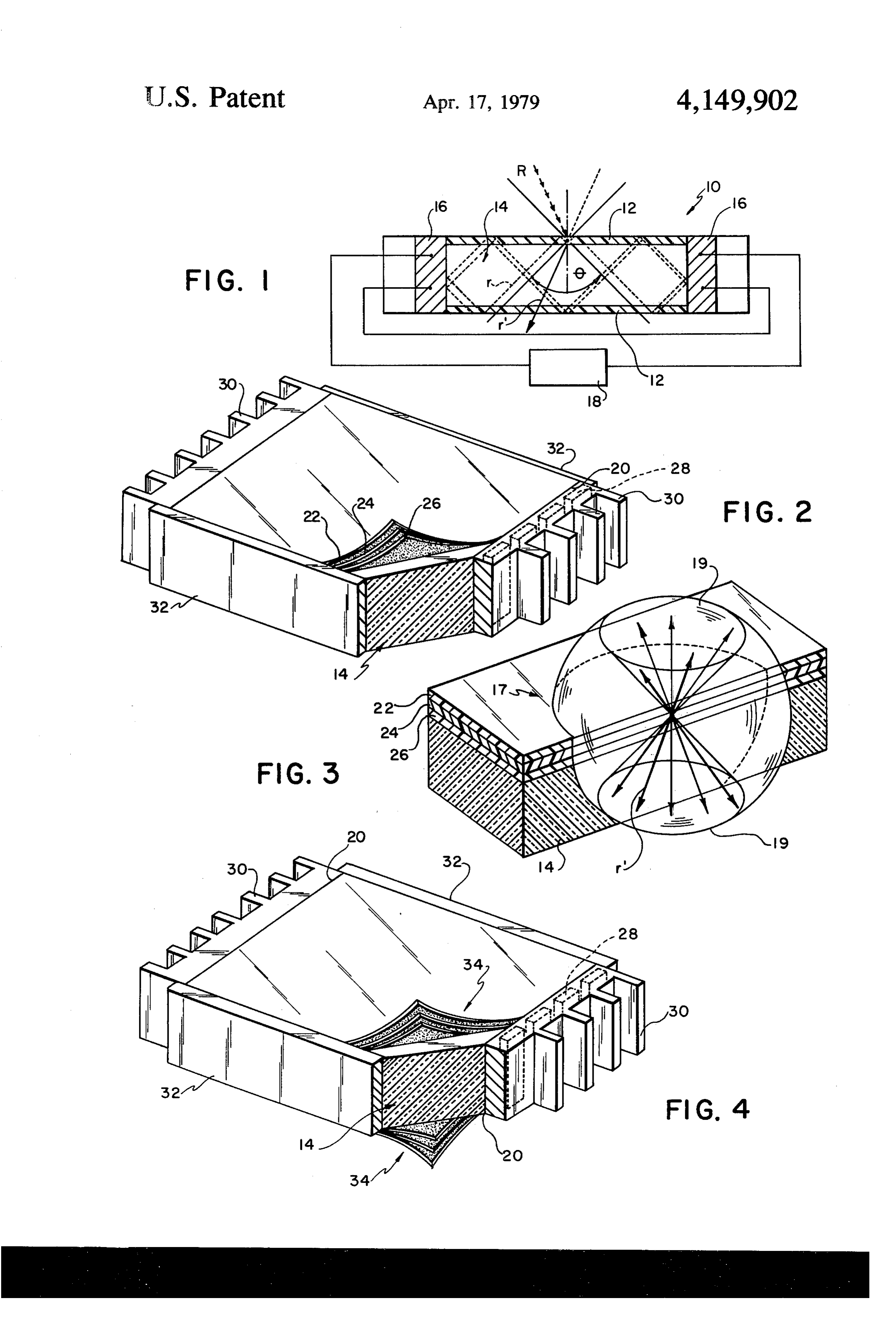
been cost-competitive with other power-generating FIG. 1 is a cross section of a solar collector having a methods because of the high cost of solar cells and other single fluorescent layer on the top and bottom of the solar energy concentrators. It is this prohibitively high transparent slab according to the present invention; cost that has made the typical "flat-array' or non-focus 25 FIG. 2 is a perspective view, partially broken away ing solar generator impractical even though it has the showing a preferred embodiment of the invention advantages of being simple and reliable. which uses three fluorescent layers on the top of the In an attempt to lower costs by reducing the cell area, transparent slab;
reflective or refractive optics have been employed to FIG. 3 is an enlarged, perspective view in partial concentrate the sunlight falling on a relatively large 30 cross section of the solar collector shown in FIG. 2 and area of the optics into a smaller area where fewer cells illustrates the fluorescent layers in more detail; may convert the concentrated radiant energy. How FIG. 4 is a perspective view similar to FIG. 2 and ever, collectors which re-direct sunlight by focusing illustrates multilayer construction above and below the require either that they be moved to accurately track slab.
the sun's apparent motion, or that they be designed for 35 DESCRIPTION OF THE PREFERRED and positioned at some comprise fixed position. In addi EMBODIMENT tion, collectors of this type are not effective to collect diffused radiation encountered when skies are overcast Reference is now made to FIG. which illustrates a or hazy. solar collector shown generally as 0 wherein a thin Use of a fluorescent concentrator of the type dis 40 layer or sheet of fluorescent material 12 is optically closed in Volume 129 of Research Disclosure published contacted with a relatively thick slab 14 of highly trans January, 1975 combines the advantages of both types of parent material such as glass or plastic. Disposed converters. One disclosed arrangement comprises a around the edges of the slab in optical contact therewith multilayer structure wherein a chamber containing fluo are arrays of energy converters 16, such as photovoltaic rescent dyes is formed by two sheets of highly transpar- 45 cells, the output of which is connected to a load 18 such ent glass with layers between the glass being separated as a motor or battery charging circuit. by a pair of transparent spacers. A first dye solution is Radiant energy, either direct, as from the sun on a contained in the chamber formed by the transparent clear day, or diffused, as encountered on overcast days, spacers. A second dye solution is contained in each of is represented by the ray R which is incident upon the the upper and lower chambers formed between one of 50 surface of the fluorescent layer 12. The fluorescent the glass plates and one of the transparent spacers. The material absorbs some of the radiation and then re-emits fluorescent dye materials are chosen so that the second radiation in a longer wavelength in all directions as dye material absorbs the fluorescence of the first dye. indicated by the dotted lines r. All the re-emitted radia The dye solutions in each of the chambers may be re tion falling outside of a cone having an angle 8 will be plenished and removed via a system of conduits so that 55 trapped by the phenomenon of total internal reflection any dye solution may be flushed and replaced without and transmitted to the edges of the slab 14 where it is disassembly of the cell when deterioration of the dye is converted by energy converters 16 to another form of observed. Sunlight that penetrates the glass sheets is energy such as heat or electricity. absorbed by the fluorescent dye and re-emitted. A large Any of the re-emitted radiation falling within the percentage of the re-emitted light piped to the edge of 60 cone having an angle 6 will escape through the surface the collector where it impinges on an energy conver of the solar collector 10; such a ray r" is shown as an sion device. example. Although the angle 8 is on the order of 90', a
SUMMARY OF THE INVENTION
relatively small portion of the re-emitted light is lost through the surface because the area of the two cap
The present invention incorporates fluorescent mate- 65 shaped segments 19 (FIG. 3) of a sphere i7 (the center rial in a thin film which is optically contacted with a of the sphere being at the point of fluorescence) sub slab of transparent material such as glass or plastic by an tended by the 90' cones is a small percentage (about ) adhesive or a viscous transparent medium. The thin film of the total surface area of the sphere.
Page 4
FIG. 3 illustrates diagramatically how each excited typical fluorescent concentrator in converting sunlight dye molecule's fluorescence is emitted into spherical to electrical power can be expressed as: Volumes surrounding the molecule. A substantial frac tion of this radiation, after passing through the glass and Efficiency dye, will strike the glass-air interface at an angle of 5 =(Fraction of incident energy absorbed and emit incidence greater than the critical angle 0 and thus will ted) be totally internally reflected. This radiation, trapped X(Fraction of emitted energy trapped) by total internal reflection will be light-piped to the X(Solar cell efficiency) edges of the glass/dye sandwich. The fraction of emit = 0.50x0.75x0.40 ted photons thus trapped and light-piped to the edges of 10 0.15 the sandwich will depend upon the index of refraction of the glass and dye layer, the transmittance of the glass The achievable efficiency in an actual device may be for the wavelengths of the fluorescence, reabsorption appreciably lower when the transmission losses of the losses in the dye, and the geometry of the cell. glass (slab material) are taken into account along with When the trapped radiation arrives at the edge of the 15 re-absorption of the emitted radiation by the dye. In dye cell 20, it will strike the solar cells 28 (FIG. 2) practice, efficiencies in the range of 1%-2% have been which are in contact with the edge. The fraction of this obtained using known dyes such as Rhodamine B for radiation which is converted to electrical power will the outermost layers, with Coumarin 6 or Fluorescien depend upon the reflection losses at the glass/photocell for the inner layers.
interface and the quantum efficiency of the solar cell 28 20 With a total system efficiency in the range of 1% to for the range of wavelengths associated with the 2% for a fluorescent concentrator of the type set forth trapped radiation. herein, the fluorescent concentrator has been found to The geometrical concentration factor for the collec be cost competitive with presently available silicon tor is approximately the surface area of the collector photovoltaic cells employed alone. For example, a fluo that is exposed to sunlight, divided by the area of the 25 rescent concentrator having an area of about one square edges of the collector. The concentration factor repre foot with a silicon photovoltaic cell array located along sents the factor by which energy density along the the edges of the concentrator, produces an output of edges of the cell would exceed the energy density inci about watt. When the same silicon cell array alone is dent on the surface of the cell, assuming that all the 30 exposed to the same intensity of sunlight, the output of incident energy is light-piped to the edges. For example, the array is about watt. The silicon cell array costs for a cell having a surface area of 1 square meter and a about five dollars. The materials used to construct the thickness of one centimeter, the ratio of surface area to one square foot fluorescent concentrator cost about two edge area is 25:1. In such a square collector, the energy dollars. Thus, the fluorescent concentrator used to pro converters near the center of the edges would receive 35 duce the watt output cost a total of seven dollars, more energy than those at the corners. To equalize the whereas to obtain the same output with silicon cells amount of energy received by the energy converters, alone would require two cell arrays costing a total of mirrors 32 (FIG. 2) may be placed on two opposite ten dollars.
edges of the collector (with their reflective surfaces In accordance with the present invention, a layer of toward the slab) with the energy conversion devices fluorescent dye may be coated on a thin transparent arranged on the two other edges of the geometric con sheet of plastic, or a second alternative is that the dye centrator. With these mirrors, the concentration ratio may be dispersed throughout the sheet of plastic; using would then be approximately doubled to about 50:1. a third arrangement, the fluorescent dye could be Of the energy emitted by the fluorescent material, the coated directly on the slab material. The former has the fraction which, ideally, would be light-piped to the 45 advantage that the fluorescent coating could be mass produced using modern roll coating techniques which edges of the collector is given by: would have a significant impact on reducing the cost. Such as arrangement would have the further advantage of providing easy periodic replenishment of the fluores where F is the fractional efficiency of the collector, n1 cent material by removing the old sheet and optically is the index of refraction of the surrounding medium; 50 bonding the new sheet to the slab. This periodic replen and n2 is the index of refraction of the fluorescent sheet. ishment is required because all known fluorescent mate If n2 is 1.5 and the surrounding medium is air (n1 = 1), rials deteriorate with age. Since many fluorescent dyes about 75% of the energy emitted by the fluorescent absorb only a limited bandwidth of solar spectrum, a material is light-piped to the edge of the collector. number of such dyes may be used to provide a more Solar cells presently in use have a peak response to 55 efficient solar energy collector. This may be accom light having a wavelength on the order of 900 m.m. with plished by using multiple layers of the coated sheets or the typical peak conversion efficiency being about 40%. coating a plurality of layers on a single sheet similar to Ideally, a fluorescent concentrator is required to oper the way various light sensitive emulsions are coated on ate utilizing terrestrial solar radiation having a spectral a substrate, one over another. Such a configuration is distribution beginning at about 400 n.m., with 70% of 60 useful in the event that the dyes selected are chemically the total incident energy at wavelengths between 400 or physically incompatible. Using multilayer coating n.m. and 850 nm. An ideal fluorescent dye for use in a techniques, the dyes can be deposited in physically and solar energy concentrator would absorb all the incident chemically separate layers, yet remain strongly opti cally coupled.
energy between 400 n.m. and 850 nm. and re-emit it with 100% quantum efficiency in a narrow band cen Such a structure is shown in FIGS. 2 and 3 wherein tered at 900 nm., the wavelength of peak response for transparent glass or plastic (Plexiglas TM) 14 is coated silicon solar cells. When all of the above factors are with three layers 22, 24, and 26 of fluorescent dye mate considered together, the overall ideal efficiency of a rial. The fluorescent dye material may be a coating of
Page 5
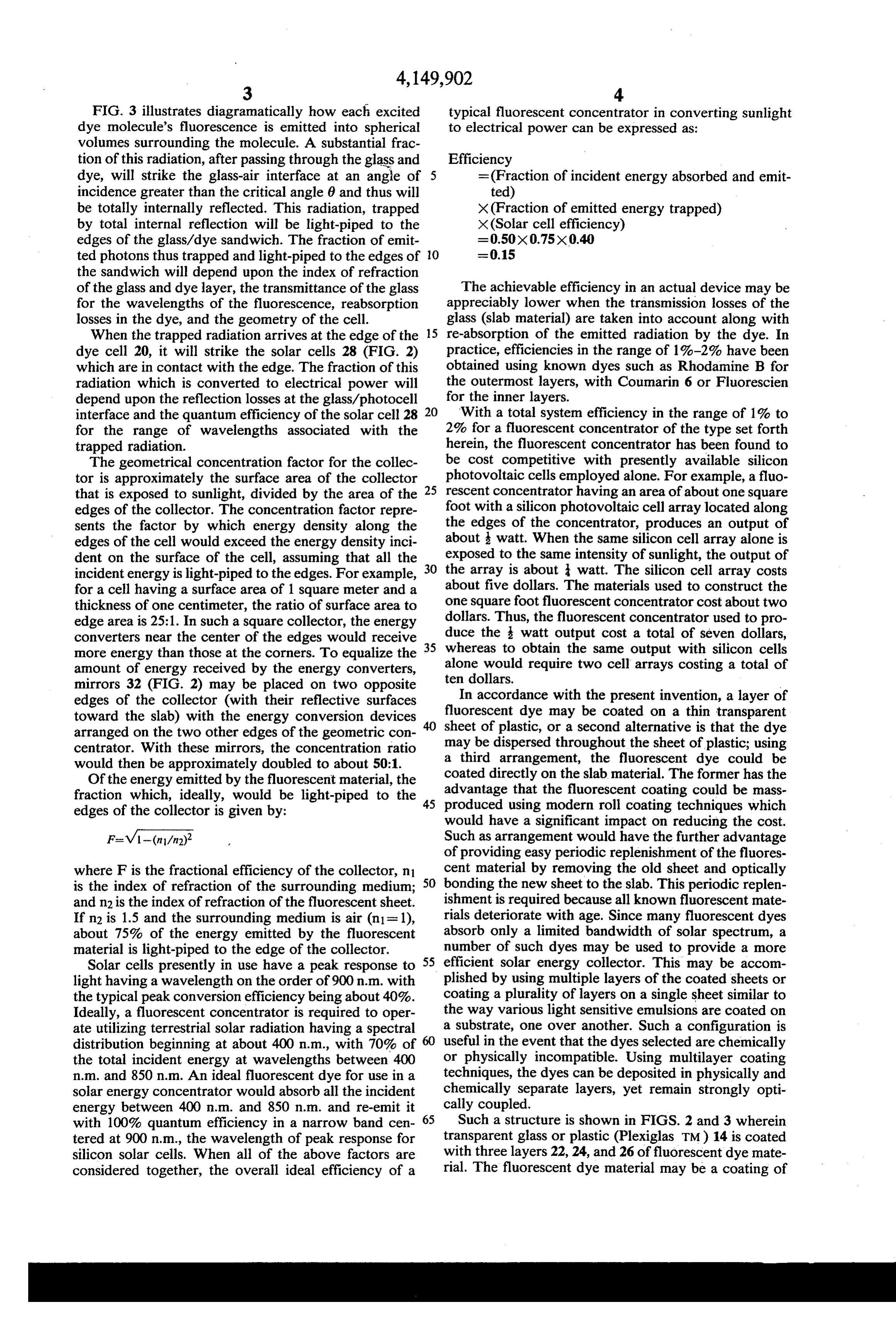
organic dye with a polymer binder on a transparent 3. The solar energy concentrator as set forth in claim plastic substrate. Alternatively, thin layers of dye con 1 wherein said second fluorescent dye absorbs a wave taining lacquer may be applied directly to the transpar length of light equal to the wavelength of light emitted ent glass or plastic by spraying, dipping, or brushing. by said first fluorescent dye.
These layers, if properly constituted, could be removed 4. The solar energy concentrator and converter of by mechanically stripping, or dissolved with a solvent, claim 1 wherein said radiation conversion means com and restored in the field without dismantling the main prise at least one photovoltaic cell. photocell-light-piping-slab structure. 5. The solar energy concentrator and converter of As shown in FIG. 3, a first fluorescent dye material is claim 1 wherein said radiation conversion means com contained in layer 24 between layers 22 and 26 which 10 prise a plurality of photovoltaic cells. contain a second dye material. Preferably, the first dye 6. A solar energy concentrator comprising: contained in the middle layer 24 will absorb a shorter a generally flat slab or optically transparent material wavelength of light than the second dye contained in having a pair of parallel opposite face surfaces layers 22 and 26. Using this arrangement, radiation defining an edge surface;
which is trapped in the middle layer 24 is re-emitted at 5 a sheet of fluorescent material substantially thinner a longer wavelength which is absorbed in either layer than said slab, said sheet being in optical contact 22 or 26, thus improving the efficiency of the collector. with one of said face surfaces of said slab and being The multi-layer structure may be extended to provide as strippable from said slab for replacement by an many fluorescent materials as necessary to absorb a 20 other such sheet, the refractive index of said sheet larger fraction of the incident solar wavelengths. being substantially equal to the refractive index of The photovoltaic cells 28 shown in FIG. 2 are said slab;
mounted on two edges of the collector and are provided and a reflective material along a portion of said edge with cooling fins 30 projecting from the back of their surface for reflecting internally-trapped radiation mounting. On the other two edges, mirrors 32 are pro 25 to the remaining portion of said edge surface; vided to keep the light from escaping from these edges. whereby incident solar radiation absorbed by the FIG. 4 illustrates a further embodiment of the inven fluorescent material is re-emitted within the slab tion wherein a plurality of thin fluorescent sheets 34 are and trapped therein by the phenomenon of total optically contacted with both the upper and lower sur internal reflection and is transmitted to the edges of faces of a transparent slab 14. Optical contact is estab 30 the slab, where it escapes to impinge upon an en lished by a fluid having the same index of refraction as ergy conversion device.
7. A solar concentrator for receiving sunlight that the slab and the sheets. Once again, it is desirable that illuminates a relatively large surface of said concentra the dye layers near the center of the structure absorb a tor and for re-emitting, light of a narrower spectral shorter wavelength of light than the outermost dye range than the received sunlight and of a ligher unit layers so that radiation which is trapped in the inner 35 intensity than the received sunlight, from a smaller layers will be re-emitted at a longer wavelength which is then totally absorbed by the outer layers, thereby surfce thereof, said solar concentrator comprising: a generally flat slab of optically transparent material improving the efficiency of the collector. The refractive having opposite first and second substantially par indices of the slab and the layers are chosen to be sub allel face surfaces and an edge of substantially stantially equal. smaller area than the area of said first face surface, The invention has been described in detail with par whereby light entering said slab through said first ticular reference to preferred embodiments thereof, but face surface at less than the critical angle deter it will be understood that variations and modifications mined by the particular refractive index of said can be effected within the spirit and scope of the inven material is reflected internally between said face tion as described herein above and as defined in the 45 surfaces and is emitted from said slab along said appended claims. edge;
We claim: a thin layer of fluorescent material optically con 1. A solar energy concentrator and converter com tacted with one of said face surfaces of said slab and prising: adapted to re-emit in all directions light of a prede a slab of optically transparent material having major 50 termined spectral range in response to illumination opposed face surfaces defining an edge surface; of said sheet by light having a broader spectral one or more removable layers of a first fluorescent range than said re-emitted spectral range, said layer dye disposed in optical contact with one or more of having a refractive index substantially equal to the said face surfaces; refractive index of said slab, and means for separa one or more removable layers of a second fluorescent 55 bly bonding said layer to said one face surface, said dye disposed in optical contact with at least one of layer thereby being easily removable for permitting said first fluorescent dye layers; a new layer of such material to be applied to that said first fluorescent dye being capable of absorbing a face surface in optical contact therewith. shorter wavelength of light than said second fluo 8. A radiant energy concentrator for converting light rescent dye; that illuminates a relatively large face surface of said the refractive indices of said slab and said layers being concentrator into light that is emitted from a smaller substantially equal; and edge surface of said concentrator, said emitted light radiation conversion means positioned along the edge having a narrower spectral range and a higher unit area surface of said slab. intensity than said illuminating light, said concentrator 2. The solar energy concentrator as set forth in claim 65 comprising:
1 wherein optical contact is established by a fluid hav a generally flat slab of optically transparent material ing the same index of refraction as said slab and said having opposite substantially flat, parallel face sur layers. faces and an optically transparent edge, whereby
Page 6
light entering said slab through one of said face substantially equal to the refractive index of said surfaces at less than the critical angle determined slab; and by the particular refractive index of said material is means for separably bonding said sheet to one of said reflected internally between said face surfaces and face surfaces of said slab in optical contact there is emitted from said slab along said edge; with such that said sheet can be easily removed and a thin fluorescent sheet optically contacted with one replaced with a new sheet of such material applied of said face surfaces of said slab and adapted to to that face surface in optical contact therewith, re-emit in all directions light of a predetermined the area of said sheet in optical contact with that relatively narrow spectral range in response to face surface being substantially larger than the area illumination of said sheet by light of a broader 10 of said edge.
spectral range, said sheet having a refractive index
Page 7
UNITED STATES PATENT OFFICE
CERTIFICATE OF CORRECTION
NVENTOR(S) : Paul B. Mauer Gene D. Turechek It is certified that error appears in the above-identified patent and that said Letters Patent are hereby corrected as shown below:
Column l, line 36 "comprise" should read -- compromise-- eigned and sealed this
Eighteenth Day of September 1979
SEAL
Attest:
LUTRELLE F. PARKER
Attesting Officer Acting Commissioner of Patents and Trademarks
Page 8
UNITED STATES PATENT OFFICE
CERTIFICATE OF CORRECTION
NVENTOR(S) : Paul B. Mauer Gene D. Turechek It is certified that error appears in the above-identified patent and that said Letters Patent are hereby corrected as shown below:
Column l, line 36 "comprise" should read -- compromise-- eigned and Sealed this
Eighteenth Day of September 1979
SEAL
Attest:
LUTRELLE F. PARKER
Attesting Officer Acting Commissioner of Patents and Tradenigris
Provenance
- Collection
- Cited prior art
- Original PDF
- patentimages.storage.googleapis.com →
- Filed
- 1977-07-27
- Pages
- 8
- Method
- pdftotext (the PDF's own text layer) + pdftoppm 300dpi page scans
- Source
- Google Patents bibliographic record
- Granted
- 1979-04-17
- Inventors
- Paul B. Mauer; Gene D. Turechek; Eastman Kodak Co
- Transcribed from
- patentimages.storage.googleapis.com →