patent · US4422434
Solar energy collection apparatus
27 December 1983
Page 1 — bibliographic record
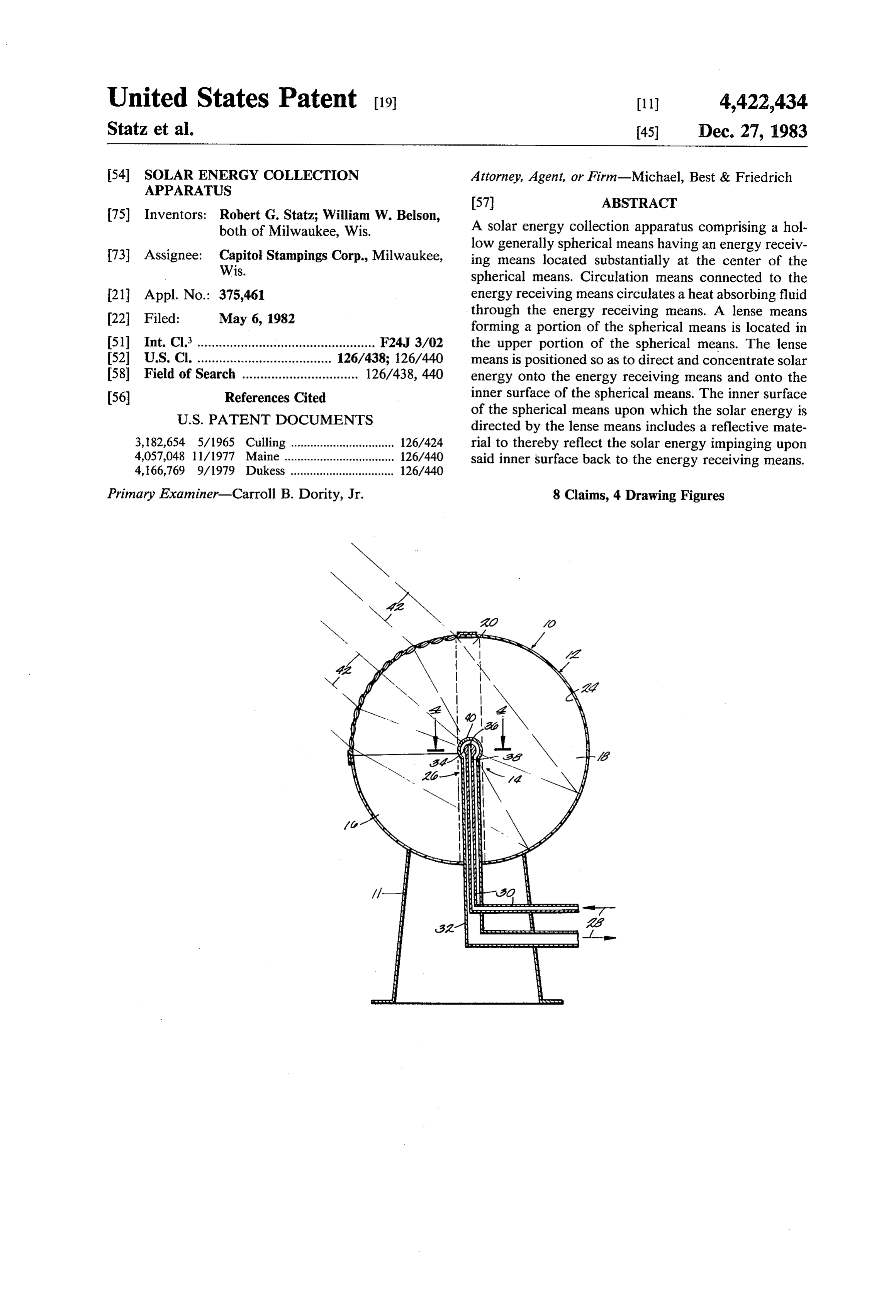
United States Patent (19) 11) 4,422,434 Statz et al. 45 Dec. 27, 1983 54). SOLAR ENERGY COLLECTION Attorney, Agent, or Firm-Michael, Best & Friedrich
APPARATUS
75 Inventors: Robert G. Statz; William W. Belson, both of Milwaukee, Wis. A solar energy collection apparatus comprising a hol 73 Assignee: Capitol Stampings Corp., Milwaukee, low generally spherical means having an energy receiv Wis.
ing means located substantially at the center of the spherical means. Circulation means connected to the 21 Appl. No.: 375,461 energy receiving means circulates a heat absorbing fluid 22 Filed: May 6, 1982 through the energy receiving means. A lense means forming a portion of the spherical means is located in 51) Int. Cl. ................................................. F24J 3/02 the upper portion of the spherical means. The lense 52 U.S. Cl. ..................................... 126/438; 126/440 means is positioned so as to direct and concentrate solar 58) Field of Search ................................ 126/438, 440 energy onto the energy receiving means and onto the 56 References Cited inner surface of the spherical means. The inner surface
of the spherical means upon which the solar energy is directed by the lense means includes a reflective mate 3,182,654 5/1965 Culling ................................ 126/424 rial to thereby reflect the solar energy impinging upon 4,057,048 11/1977 Maine ........ ... 126/440 said inner surface back to the energy receiving means. 4,166,769 9/1979 Dukess ................................ 126/440
Primary Examiner-Carroll B. Dority, Jr. 8 Claims, 4 Drawing Figures
Page 2
Drawing sheet — no readable text.
Page 3
stantially at the center of the spherical means. Circula
SOLAR ENERGY COLLECTION APPARATUS tion means connected to the energy receiving means circulates a heat absorbing fluid through the energy
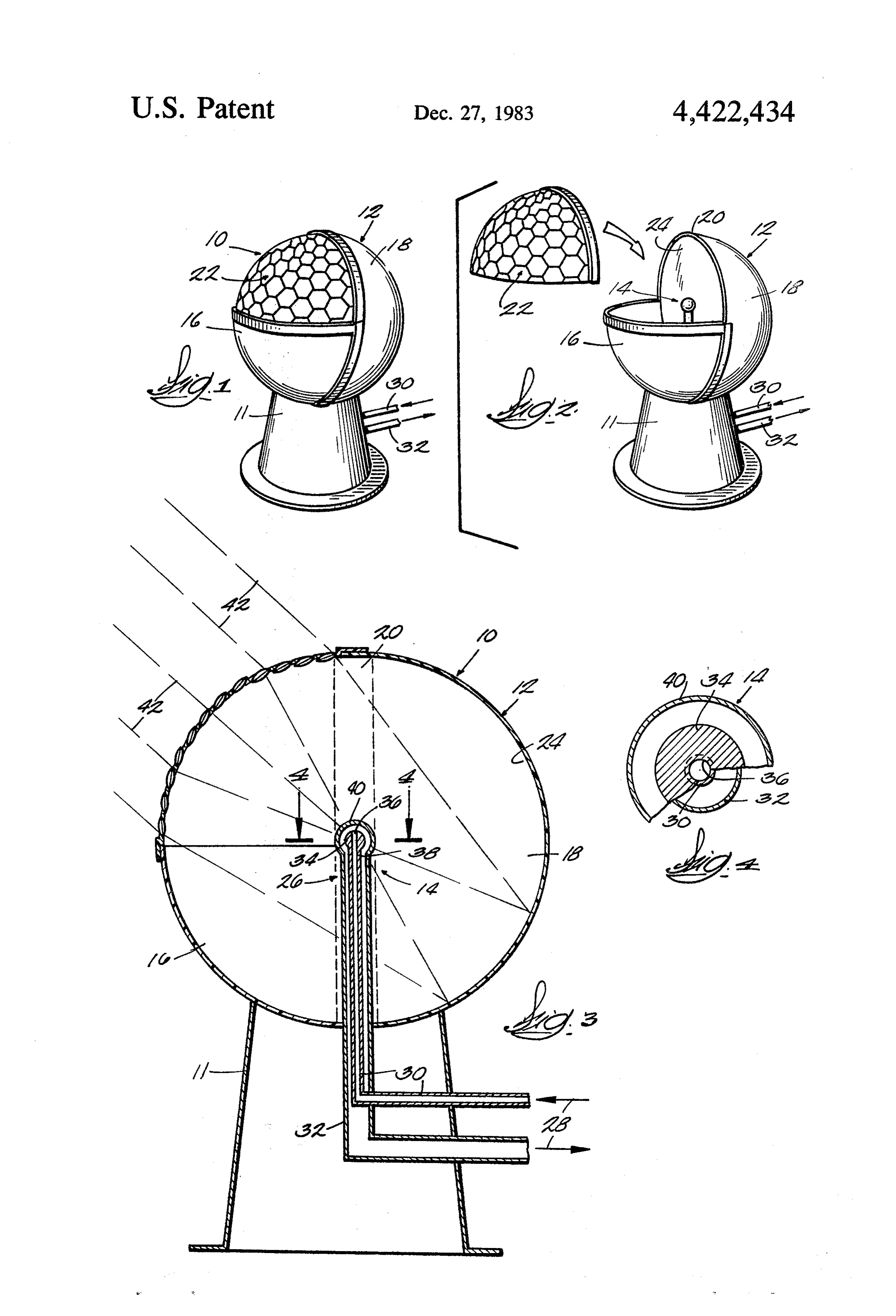
BACKGROUND OF THE INVENTION receiving means. A lenses means forming a portion of This invention relates to solar energy collection appa 5 the spherical means is located in the upper portion of ratuses and, more particularly, to apparatuses of agen the spherical means. The lenses means is positioned so erally spherical nature making use of a plurality of as to direct and concentrate solar energy onto the en lenses for concentrating the solar energy of the sun onto ergy receiving means and onto the inner surface of the an energy receiving means. spherical means. The inner surface of the spherical It has become, especially desirable in recent years to O means upon which the solar energy is directed by the develope more efficient means for extracting energy lenses means includes a reflective material to thereby from the sun. A number of approaches have been made reflect the solar energy impinging upon said inner sur to solving the problem of collecting solar energy effi face back to the energy receiving means. ciently, but many of these approaches have been im In one embodiment of this invention, the generally practical for various reasons. 15 spherical means is comprised of two hemispherical por Some systems use optical lenses for the purpose of tions connected by a vertical cylindrical portion. The concentrating the radiant energy of the sun onto various lenses means forms the upper half of one of the hemi means for extracting the solar energy. Some such ap spherical portions of the generally spherical member, proaches have incorporated the use of a reflective sur and includes a plurality of lenses concentrically-focused face in conjunction with lenses to help focus the sun's 20 on the energy receiving means. energy onto the energy receiving mechanism. Examples of such devices can be found in the following U.S. DESCRIPTION OF THE DRAWINGS Patents: FIG. is a perspective view of a solar energy collec
tion apparatus.
Patentee U.S. Pat. No. FIG. 2 is a perspective view of the solar energy col Kelly 4,168,696 lection apparatus in FIG. with the lense portion re Niederle 1989,999 moved showing the location of an energy receiving Culling 3,182,654 sphere and reflective inner surfaces of the hollow 30 sphere.
A number of U.S. patents disclose the use of a plural FIG. 3 is a cross-sectional view of the apparatus in ity of lenses in a generally spherical form for the pur FIG. 1.
pose of concentrating the sun's solar energy onto some 4-4 FIG. 4 is an enlarged sectional view taken along line heat receiving means. Dukess U.S. Pat. No. 4,166,769 of FIG. 3.
discloses the use of a generally spherical member com 35 DESCRIPTION OF THE PREFERRED prising a plurality of lenses with an expandable energy EMBODIMENT receiving member at the center of the spherical mem ber. Davis U.S. Pat. No. 4,136,670 discloses the use of a One embodiment of this invention is a solar energy hemispherical plurality of lenses used for concentrating collection apparatus 10 including a hollow generally the sun's radiant energy onto a circular collector dish. 40 spherical member 12 with an energy receiving means or Maine U.S. Pat. No. 4,057,048 discloses the use of a sphere 14 mounted at the center of the generally spheri hemispherical member for concentrating the sun's radi cal member 12. The spherical member 12 is mounted on ant energy onto a shallow tray of water. a suitable support 11.
Dandini U.S. Pat. No. 3,934,573 describes the use of a The hollow generally spherical member 12 as con spherical member containing a plurality of lenses for the 45 structed consists of two hemispherical portions 16 and purpose of concentrating the sun's radiant energy onto 18 with a vertically oriented cylindrical portion 20 con a boiler located at the center of the spherical member. necting the two hemispherical portions 16 and 18. The Heat absorbing fluid is transmitted through the boiler cylindrical portion 20 is approximately equal in width for purposes of absorbing heat for conversion to useful to the diameter of the energy receiving sphere 14. This power. 50 construction provides for a more optimum focusing and reflecting of the sun's rays onto the energy receiving
SUMMARY OF THE INVENTION sphere 14.
One of the principal objects of this invention is to Located in an upper portion of the generally sperical provide a solar energy collection apparatus which is member 12 is a lenses means 22 comprising a plurality of relatively compact but capable of absorbing a signifi 55 lenses concentrically focused on the energy receiving cant amount of solar energy. sphere 14. This lenses means 22 forms the upper half of Another of the principal objects of this invention is to the hemispherical portion 16 of the generally spherical provide a solar energy collection apparatus which is member 12 (as shown in FIG. 1). The lenses are of a one generally more efficient than currently available solar piece construction of plastic molded by conventional energy collection apparatuses. 60 eaS.
Another of the principal objects of this invention is to Substantially all of the generally spherical member 12 provide a solar energy collection apparatus which will other than the lenses means 22 is made of steel or some maintain a reasonable orientation with the sun without other suitable material with either polished reflective having to mechanically adjust its orientation. inner surfaces 24 or some other reflective surface ap For the achievement of the above and other objec 65 plied thereto.
tives, this invention provides a solar energy collection Located at the center of the generally spherical mem apparatus comprising a hollow generally spherical ber 12 is an energy receiving means or sphere 14. The means having an energy receiving means located sub energy receiving sphere 14 is made of a heat conductive
Page 4
material such as copper and is painted with a radiant means upon which sun rays are directed by said energy absorbing paint. The ratio of the area of the lenses: means including a reflective material to inside surface of the generally spherical member and the thereby reflect said sun rays impinging upon said area of the outside surface of the energy receiving inner surface back to said energy receiving means. sphere is about 19 to 1. 5 2. An apparatus for collecting solar energy compris Connected to the radiant energy receiving sphere 14 ing: . . . . . .. . . .. .. ... ..fit. . . are circulating means 26 for circulating a heat absorbent an energy receiving means; . . . . . . . . . fluid 28, such as water, through the receiving means 14. a circulating means connected to said energy receiv The energy receiving means 14 and the circulating ing means for circulating a heat absorbing fluid means 26 consist of an outer cylindrical pipe 32 and an 10 through said receiving means; and inner cylindrical pipe 30 positioned at the center of the a hollow, generally spherical means with said energy outer pipe 32. One end 38 of the inner cylindrical pipe receiving means positioned substantially at the 30 extends into a bore 36 through the center of an inner center thereof, said hollow, generally spherical sphere 34 attached to the end 38 of the inner pipe 30. A means including a lenses means forming a portion hollow outer sphere 40 is positioned with the inner 15 of said spherical means and located in the upper sphere 34 at the center of the outer sphere 40 and the portion thereof, said lenses means positioned to outer pipe 32 extends into the outer sphere 40 and is direct and concentrate a substantial portion of sun attached to the outer sphere 40. rays passing therethrough onto said energy receiv The heat absorbing fluid 28 enters into the inner cy ing means and the remaining portion passing there lindrical pipe 30, goes up through the inner sphere 34, 20 through onto the inner surface of said spherical and then around the inner sphere 34 to inside the outer means, said inner surface of said spherical means sphere 40, where the fluid is then heated by the energy upon which sun rays are directed by said lenses impinging upon the outer surface 18 of the outer sphere means including a reflective material to thereby 40. The fluid then passes down and around the inner reflect said sun rays impinging upon said inner cylindrical pipe 30 through the outer cylindrical pipe 32 25 surface back to said energy receiving means. where it will then exists to be used for domestic water 3. An apparatus according to claims 1 or 2, and heating or some other purpose. wherein said hollow generally spherical means com The solar energy collection apparatus when in use prises two hemispherical portions connected by a verti will be positioned so that the lenses means 22 faces in a cal cylindrical portion.
southerly direction so that during a majority of the day 30 4. An apparatus according to claims 1 or 2, and the sun will impinge upon the plurality of lenses. As the wherein said lenses means comprises generally the sun moves across the southern sky, a majority of the upper half of one of said hemispherical portions. sunlight 43 impinging on the lenses will be focused upon 5. An apparatus according to claims 1 or 2, and the energy receiving sphere 14, as shown in FIG. 3. The wherein said energy receiving means and said circulat rays 42 of the sun impinging upon the lenses which do 35 ing means comprise:
not become focused on the sphere will impinge the an inner sphere with a bore extending through it reflective inner surface 24 of the sphere, and will be center, focused by the reflective surface 24 onto the energy an inner cylindrical pipe extending into said bore and receiving means 14. attached to said inner sphere, It is to be understood that the invention is not con- 40 a hollow outer sphere with said inner sphere posi fined to the particular construction or arrangement of tioned at its center, and parts herein illustrated and described, but embraces all an outer cylindrical pipe with said inner cylindrical such modified forms that come within the scope of the pipe positioned at its center, said outer cylindrical following claims. pipe extending into and attached to said outer We claim: 45 sphere.
1. An apparatus for collecting solar energy compris 6. An apparatus according to claims 1 or 2, and ing: wherein said energy receiving means comprises a hol an energy receiving means; low heat conductive sphere with a radiant energy ab a circulating means connected to said energy receiv sorbing paint covering.
ing means for circulating a heat absorbing fluid 50 7. An apparatus according to claim 6 wherein said through said receiving means; and hollow heat conductive sphere has an outer surface and a hollow, generally spherical means with said energy wherein said hollow generally spherical means has an receiving means positioned substantially at the inner surface and wherein the ratio of the area of said center thereof, said hollow, generally spherical hollow generally spherical means inner surface and the means including a leanse means forming a portion 55 area of said hollow heat conductive sphere's outer sur of said spherical means and located in the upper face is about 19 to 1.
portion thereof, said lenses means positioned to 8. An apparatus according to claims 1 or 2, and direct and concentrate sun rays onto said energy wherein said lenses means comprises a plurality of lense receiving means and onto the inner surface of said concentrically-focused on said energy receiving means. spherical means, said inner surface of said spherical sk k xz k sk
Page 5
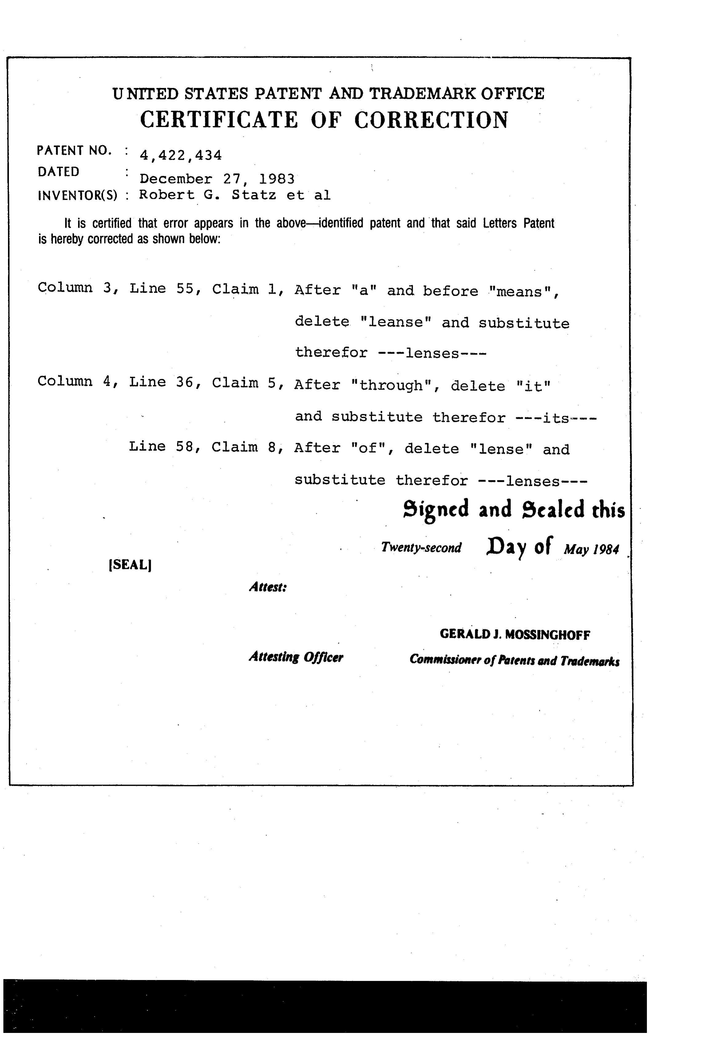
UNITED STATES PATENT AND TRADEMARK office
CERTIFICATE OF CORRECTION
INVENTOR(S) : Robert G. Statz et al.
it is certified that error appears in the above-identified patent and that said Letters Patent is hereby corrected as shown below:
Column 3, Line 55, Claim l. After "a" and before "means", delete "leanse" and substitute therefor ---lenses---
Column 4, Line 36, Claim 5, After "through", delete "it" and substitute therefor ---its---
Line 58, Claim 8, After "of", delete "lense" and substitute therefor ---lenses--- signed and sealed this
Twenty-second D 2 y of May 1984
SEAL
Attest
GERALD J. MossINGHoFF
Attesting Officer Commissioner of Patents and Trademarks
Provenance
- Collection
- Cited prior art
- Original PDF
- patentimages.storage.googleapis.com →
- Filed
- 1982-05-06
- Pages
- 5
- Method
- pdftotext (the PDF's own text layer) + pdftoppm 300dpi page scans
- Source
- Google Patents bibliographic record
- Granted
- 1983-12-27
- Inventors
- Robert G. Statz; William W. Belson; Capitol Stampings Corp
- Transcribed from
- patentimages.storage.googleapis.com →