patent · US4175980
Luminescent solar collector
27 November 1979
Page 1 — bibliographic record
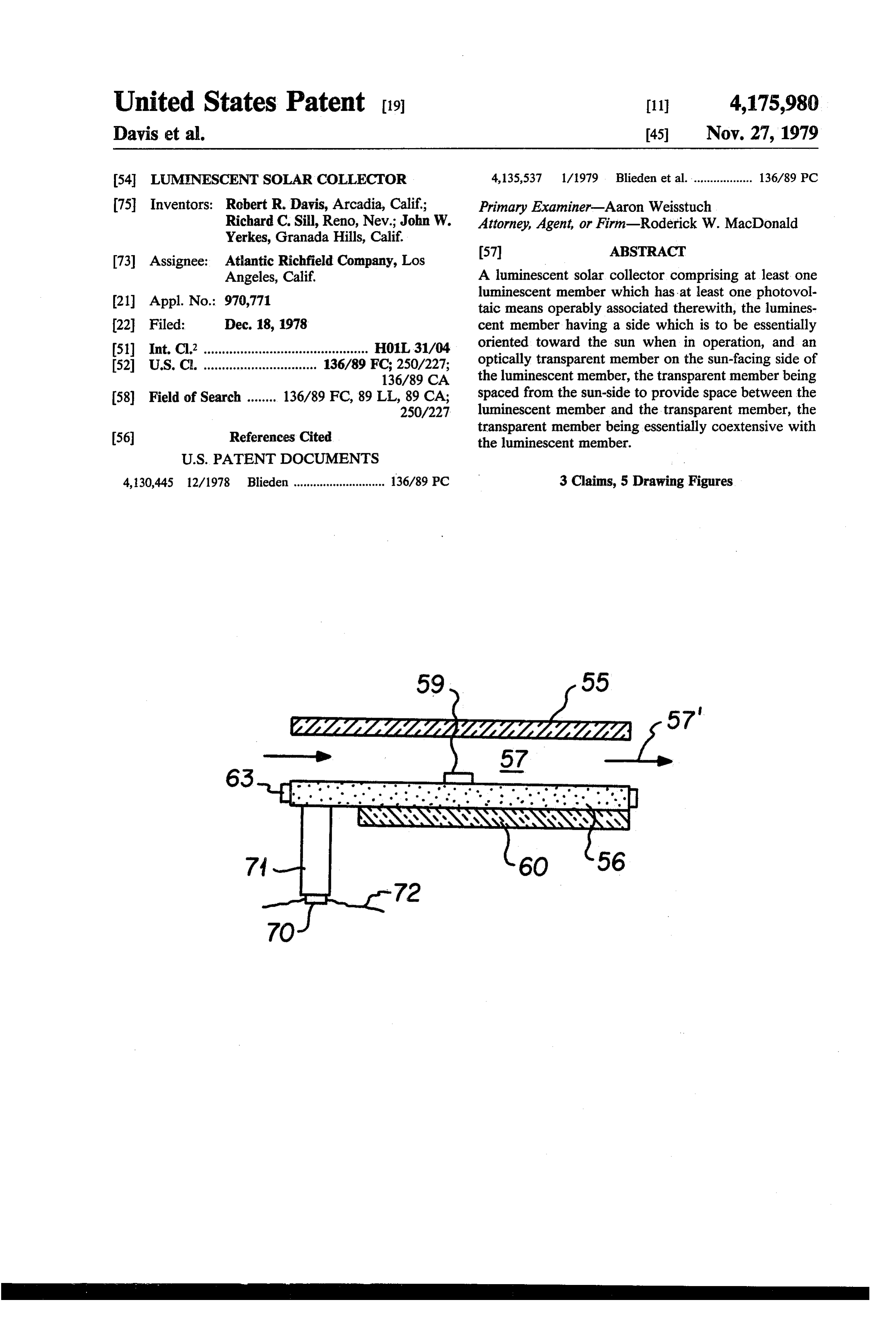
United States Patent (19) 11 4,175,980 Davis et al. 45 Nov. 27, 1979 54 LUMENESCENT SOLAR COLLECTOR 4,135,537 1/1979 Blieden et al. ................... 136/89 PC (75) Inventors: Robert R. Davis, Arcadia, Calif; Primary Examiner-Aaron Weisstuch Richard C. Sill, Reno, Nev.; John W. Attorney, Agent, or Firm-Roderick W. MacDonald Yerkes, Granada Hills, Calif.
73 Assignee: Atlantic Richfield Company, Los
Angeles, Calif. A luminescent solar collector comprising at least one 21 Appl. No.: 970,771 luminescent member which has at least one photovol taic means operably associated therewith, the lumines 22 Filed: Dec. 18, 1978 cent member having a side which is to be essentially 51) Int. Cl? ............................................. HOL 31/04 oriented toward the sun when in operation, and an 52 U.S. C. ............................... 136/89 FC; 250/227; optically transparent member on the sun-facing side of 136/89 CA the luminescent member, the transparent member being 58 Field of Search ........ 136/89 FC, 89 LL, 89 CA; spaced from the sun-side to provide space between the 250/227 luminescent member and the transparent member, the
transparent member being essentially coextensive with the luminescent member.
4,130,445 12/1978 Blieden ............................ 136/89 PC 3 Claims, 5 Drawing Figures
Page 2
Drawing sheet — no readable text.
Page 3
member carried on said sun oriented side (or sides) of
LUMNESCENTSOLAR COLLECTOR said luminescent member, said transparent member being spaced from said sun-side, said transparent mem
BACKGROUND OF THE INVENTION ber being essentially coextensive with said luminescent It is known that a photovoltaic semiconductor p-n 5 member.
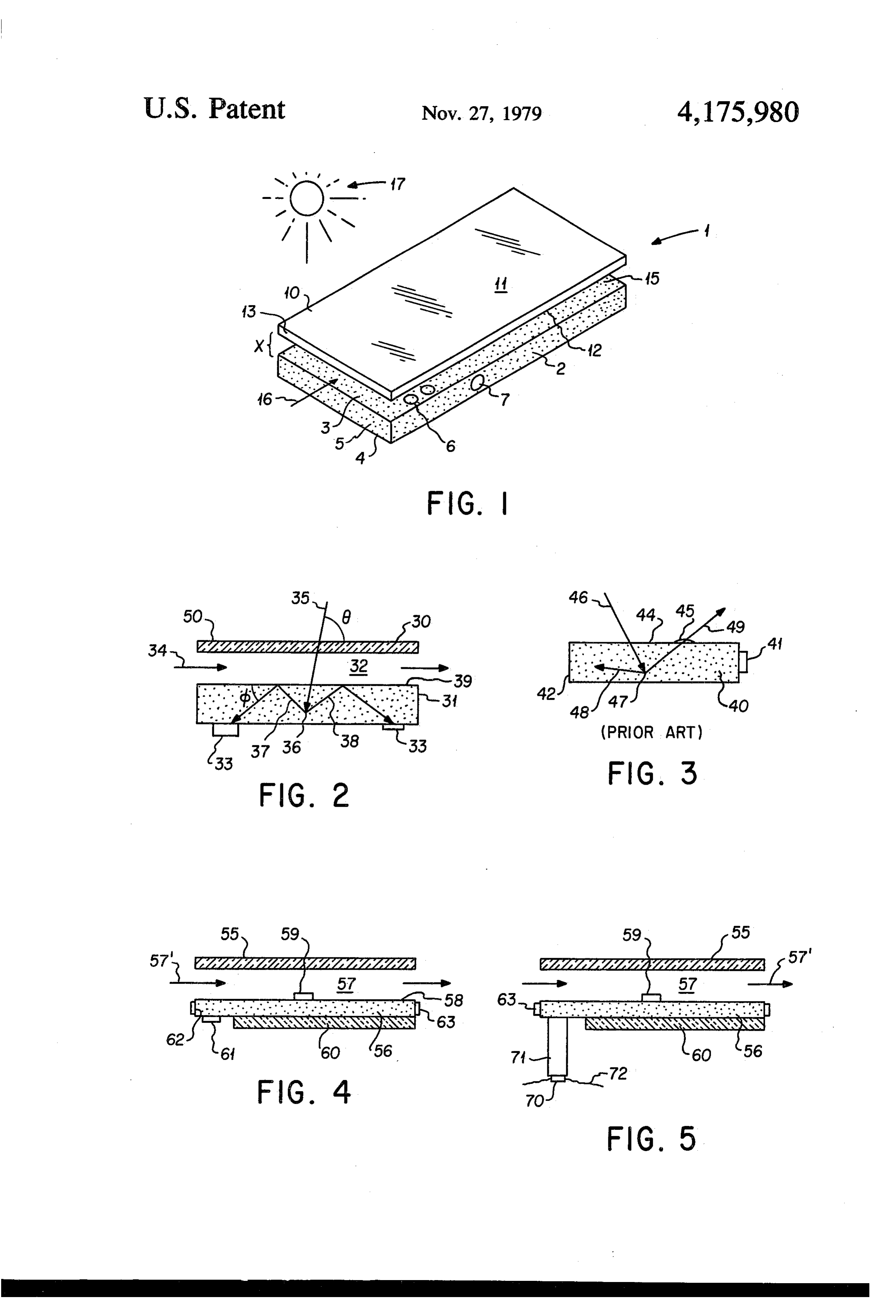
junction can convert to electricity only that portion of Accordingly, it is an object of this invention to pro the incident photon energy spectrum, typically solar vide a new and improved luminescent solar collector. radiation, which creates hole-electron pairs within a Other aspects, objects and advantages of this inven given semiconductor material. For example, in a silicon 10 tion will be apparent to those skilled in the art from this photovoltaic cell only that portion of the solar spectrum disclosure and the appended claims. with energy slightly greater than or equal to the 1.1 electron volt band gap is efficiently converted into BRIEF DESCRIPTION OF THE DRAWINGS electricity. Photons of lesser energy are not absorbed at FIG. 1 shows one embodiment of a collector within all. More energetic photons are absorbed and most of 15 this invention.
the energy lost in heating the cell. It is this heating and FIG. 2 shows a side view of another embodiment absorption process which can degrade the cell's energy within this invention.
conversion efficiency. To maximize the efficiency of a FIG. 3 shows a prior art device. given photovoltaic cell, it is advantageous to convert as FIG. 4 shows yet another embodiment within this much of the available light as possible into an energy invention.
range to which such cell can optimally respond in the FIG. 5 shows another embodiment within this inven generation of electricity before the light strikes the tion.
cell's surface.
One technique for achieving such conversion takes DETALED DESCRIPTION OF THE advantage of the fact that light falling upon alumines 25 INVENTION cent agent is characteristically reradiated or emitted in FIG. 1 shows a luminescent solar collector 1 having a band of wavelengths of known energy content. Also, a lower luminescent member 2 which has an upper side light absorbed by such an agent in one direction is rera diated isotropically. Such agents include, for example, 3sides. and a lower side 4, both sides being large surface aea Member 2 has upstanding edge face 5 extending pigments, metal oxides and organic dyes which are used 30 around its periphery. Bottom side 4 carries a plurality of in scintillation counters, lasers, and the like. For the purpose of this invention the term "luminescent agent” photovoltaic cells 6 and edge face 5 also carries photo includes all types of luminescent agents exhibiting all finite distanceSpaced voltaic cell 7.
above upper side 3 of member 2 a optically transparent member 10 species of luminescence, including, but not limited to, which has an upper large area side 11 and a lower large fluorescence and phosphorescence. area side 12, the sides being connected by a peripheral It has been shown that the dispersal of a luminescent upstanding edge face 13. Transparent
agent within a sheet of glass or plastic, one of whose essentially coextensive with member 2 somember that it
covers major surfaces is exposed to light, concentrates and essentially all of member 2 but has space between bot focuses a flux of light of known energy toward one or tom side 12 of member 10 and upper side 3 of member more of the thin edge faces of the sheet. If a photovol 2, such space being designated by reference numeral 15. taic cell responsive to light at that energy level is opti This space cally coupled to such edge face, the energy conversion therethroughcanascarry, if desired, a cooling fluid passing efficiency of the cell increases. In this invention a light will be describedshown by arrow 16 for reasons which hereinafter, that fluid being preferably transmissive member of such construction and proper a gas.
ties is termed a “luminescent member' and a photovol taic solar collector employing such a member is termed 45 In normal operation upper side 3 of member 2 will be a “luminescent solar collector'. A luminescent solar oriented generally in the direction of the sun 17 so that collector of this type is fully and completely disclosed member 10 is carried adjacent sun oriented side 3. FIG. 2 shows a collector in accordance with this in Optics, Vol. 15, No. 10, pages 2299-2300, dated Octo invention wherein upper transparent member 30 is car ber, 1976, the disclosure of which is incorporated herein by reference. 50 ried spaced away from lower luminescent member 31 It is desirable once light enters the interior of the thereby defining space 32 between the members. As luminescent member that it be internally reflected mentioned hereinabove, heat can be deleterious to the therein until it finally reaches a photovoltaic cell and efficiency of photovoltaic cells such as cells 33 on mem does not escape out of the luminescent member by re ber 31. Therefore, it can be desirable to supplementally fraction or otherwise before it reaches the photovoltaic 55 cool member 31 such as passing a cooling fluid (liquid, cell. This invention improves the retention of light in gas, or mixture thereof) through space 32 as shown by the luminescent member of an operating luminescent arrow 34. Additionally the cooling fluid can have an solar collector when that collector is exposed to normal index of refraction near the indices of refraction of weather and other operating conditions. members 30 and 31, or at least nearer than the index for air, to aid in the transmission of light through space 32,
SUMMARY OF THE INVENTION or at least make such transmission easier than if only air According to this invention there is provided a lumi filled space 32.
nescent solar collector which has at least one lumines Luminescent member 31 carries dispersed through cent member, which member has operably associated out the interior thereof luminescent agent(s). When a therewith at least one photovoltaic means, the lumines 65 ray of sunlight 35 reaches the interior of member 31, at cent member having a particular side (or sides) which is some point in that interior it will impinge upon a lumi to be approximately oriented towards the sun when the nescent agent particle 36. The luminescent agent parti collector is in operation, and an optically transparent cle absorbs ray35 and re-emits light in a different, lower
Page 4
energy range. A large plurality of subrays are emitted and the like. Means 63 will tend to reflect light back into but only two, subrays 37 and 38, are shown for sake of the interior of member 56 rather than allowing it to clarity. The subrays are re-emitted at angles different escape through the edge face. p. FIG. 5 shows the de from the original angle of incidence 6 of ray 35, for vice of FIG. 4 except that photovoltaic means 61 has example angled for subray 37. Because of the different 5 been eliminated and replaced by a physically remote angles of light emission from particle 36, reflection of photovoltaic means 70, luminescent member 56 and the subrays off upper side. 39 of member 31 is maxi photovoltaic means 70 being optically coupled to one mized. For example, subray 37 at angle d which is dif another by optic means 71 which can employ conven ferent from angle 6 will more likely be reflected offside tional fiber optics techniques although member 71 is not 39 back towards photovoltaic cell 33, similar internal 10 limited to fiber optics. Member 71 could be a right reflection occurring for the other subrays such as sub cylindrical solid piece of glass or plastic whose cross ray 38. sectional configuration matches the shape of photovol Prior art devices such as the one shown in FIG. 3 taic cell 70. As with all other photovoltaic cells de employ a luminescent member 40 having a photovoltaic scribed hereinabove, electricity is recovered from the cell 41 on upstanding edge face 42. When such a device 15 cell by way of wires such as wires 72 for cell 70, the is exposed to normal weather elements or other vagaries wires for the other cells not being shown for sake of of conventional use, e.g., birds, sun oriented side 43 simplicity. By this embodiment, cell 70 is physically which is the side exposed to such elements becomes removed from member 56 and, therefore, not heated by dirty, scratched or otherwise contaminated, for exam member 56 when in operation. Cell 70 could be in a ple by water drop 45. In this prior art device, when light 20 cooling fluid stream or otherwise cooled on its own ray 46 reaches the interior of member 40 and impinges since it can be located away from member 60. on aluminescent agent particle 47 thereby giving rise to The light transmitting member matrix material and a plurality of subrays, such as subrays 48 and 49, some of the luminescent member matrix material can be the the subrays are directed back towards upper surface 44. same or different but are preferably a polymeric or glass If those subrays struck upper surface 44 in the area of a 25 material which is transparent at least to the visible light residing contaminant such as water drop 45 which drop spectrum. Such matrix material can therefore be of has an index of refraction closer to the index of refrac conventional plastic polymeric material such as poly tion of member 40 than the air surrounding side 44, methylmethacrylate, other known acrylic polymers, subray 49 would be more likely to escape because of the styrene polymers, and the like. The material can be glass aid of the intermediate index of refraction contaminant 30 or other transparent material into which luminescent 45. Thus, maximum internal reflection of subrays within agents can be incorporated and which, like the poly prior art member 40 is not achieved. meric material, are nondeleterious to the luminescent By the use of the transparent member 11 in FIG. 1 or agents, the photovoltaic cells, and the like. The matrix transparent member 30 in FIG. 2, contaminants are not material can be any light transmitting material hereto allowed to reach the upper surface of the luminescent 35 fore used in the manufacture of conventional nonlu member but rather are kept on the upper surface of the minescent photovoltaic devices. The matrix materials transparent member so that escape of subrays from preferable do not contain impurities such as iron and the within the luminescent member as illustrated for FIG. 3 like which would absorb light rather than allow it to does not occur with the collector of this invention. For pass on to the photovoltaic cell. example, as can be noted by referring to FIG. 2, con 40 The luminescent agents can include metals or oxides taminants would be retained on upper surface 50 of or other compounds of metals such as neodymium oxide transparent member 30 and would not reach upper employed in a glass matrix or one or more laser dyes surface 39 of member 31. Thus, subrays 37 and 38 would such as the coumarin family of dyes and the rhodamine not have a chance to escape by way of contaminants family of dyes. These dyes are quite complex chemi from the collector of this invention as they would from 45 cally. All of these materials and the characteristics the collector of the prior art of FIG. 3. thereof are well known in the art and are commercially FIG. 4 shows a collector within this invention available so that further detailed description is unneces wherein upper transparent member 55 is spaced above sary to inform one skilled in the art. lower luminescent member 56 to provide intermediate The luminescent agent or agents are simply dispersed space 57 through which fluid can flow as shown by 50 in the matrix material by mixing or other dispersion arrow 57". FIG. 4 shows that a photovoltaic means can while the matrix material is in a fluid state due to the be employed on the upper surface 58 of member 56 as heating and the like.
shown by photovoltaic cell 59. Photovoltaic cell 59 will Photovoltaic cells are well known in the art and vary be directly cooled by the fluid passing through space 57. widely as to their characteristics and can include, with Such fluid can be substantially heated by its passage 55 out limitation, silicon, germanium, gallium arsenide, and through space 57 and therefore energy in the form of many other known semiconductor materials. heat can be recovered from this fluid in addition to Reasonable variations and modifications are possible electricity being recovered from the photovoltaic cells. within the scope of this disclosure without departing Thus, to maximize the capture of this heat energy, insu from the spirit and scope of this invention. lation means 60 can be employed on the bottom side of 60 The embodiments of the invention in which an exclu luminescent member 56 to retain heat for capture by the sive property or privilege is claimed are defined as cooling fluid. If photovoltaic means 61 are also em follows:
ployed on the bottom side of member 56, the thermal 1. A luminescent solar collector comprising at least insulation means is employed over that area of the un one luminescent member having at least one photovol derside which is not covered by photovoltaic means. 65 taic means operably associated therewith, said photovo Also, to help maximize internal reflection, upstanding latic means being physically removed from said lumi edge face 62 of luminescent member 56 can be covered nescent member and optically coupled with said lumi by a reflective means 63 such as a mirror, shiny metal, nescent member by optic means, said luminescent mem
Page 5
ber having at least one side which is adapted to be ori side of said luminescent member, and the area of said ented toward the sun and an edge face, a light transpar underside which is not covered by photovoltaic means ent member carried adjacent to and in spaced relation is essentially covered by thermal insulation means. from said sun-side of said luminescent member, said 3. A collector according to claim 1 wherein at least transparent member being essentially coextensive with 5 part of said edge face of said luminescent member carry said luminescent member.
2. A collector according to claim 1 wherein at least reflective means.
part of the photovoltaic means are carried on the under
Provenance
- Collection
- Cited prior art
- Original PDF
- patentimages.storage.googleapis.com →
- Filed
- 1978-12-18
- Pages
- 5
- Method
- pdftotext (the PDF's own text layer) + pdftoppm 300dpi page scans
- Source
- Google Patents bibliographic record
- Granted
- 1979-11-27
- Inventors
- Robert R. Davis; Richard C. Sill; John W. Yerkes; Atlantic Richfield Co
- Transcribed from
- patentimages.storage.googleapis.com →