patent · US4379613A
Solar energy collector
12 April 1983
Page 1 — bibliographic record
United States Patent (19) 11) 4,379,613 Coburn (45) Apr. 12, 1983 54). SOLAR ENERGY COLLECTOR Apr.-Jun. 1980, "Fluorescent Windows for Liquid (75) Inventor: John F. Coburn, Cranford, N.J. Junction ...," pp. 333-342. (73) Assignee: Exxon Research and Engineering Co., Edwards, NASA Tech. Briefs, Summer 1978, "Optics for Natural Lighting', pp. 209-211.
Florham Park, N.J.
(21) Appl. No.: 236,824 Primary Examiner-John D. Lee Assistant Examiner-Frank Gonzalez (22 Filed: Feb. 23, 1981 Attorney, Agent, or Firm-Joseph J. Dvorak 51) Int. Cl............................................... G02B5/172 52 U.S. Cl. ................................. 350/96.10; 136/247; 57 ABSTRACT 136/259 The present invention comprises a planar fluorescent 58 Field of Search ............... 350/96.10, 96.12, 96.15, solar concentrator having a circular band portion 350/96.16, 96.24; 136/247, 259 within said concentrator toward which incident solar (56) References Cited radiation is redirected. Optically coupled to said circu
ally symmetrical body of light transmitting material 4,078,548 3/1978 Kapany ............................ 350/96.10 having a circular band at one end for the receipt therein 4,149,902 4/1979 Mauer et al. .......................... 136/89 4,175,980 1 1/1979 Davis et al. ... 36/89 of radially directed electromagnetic radiation, said opti 4,188,238 2/1980 Boling ................................... 136/89 cal means including a body portion, having a coating on 4,199,376 4/1980 Sill ......... ... 36/89 FC the exterior surfaces thereof and a generally circular 4,275,950 6/1981 Meyer ........ ... 350/96.10 second end. Light radially directed in said circular band 4,292,959 10/1981 Coburn, Jr. ......................... 350/262 at said first end is internally reflected in said body por FOREIGN PATENT DOCUMENTS tion and directed toward said second end, whereby the 436046 11/1967 Switzerland ..................... 350/96.10 light leaving that circular second end is distributed substantially uniformly over the entire area thereof.
OTHER PUBLICATIONS
Kazacos et al., Solar Energy Materials, vol. 2, No. 3, 7 Claims, 5 Drawing Figures
Page 2
Drawing sheet — no readable text.
Page 3
SOLAR ENERGY COLLECTOR
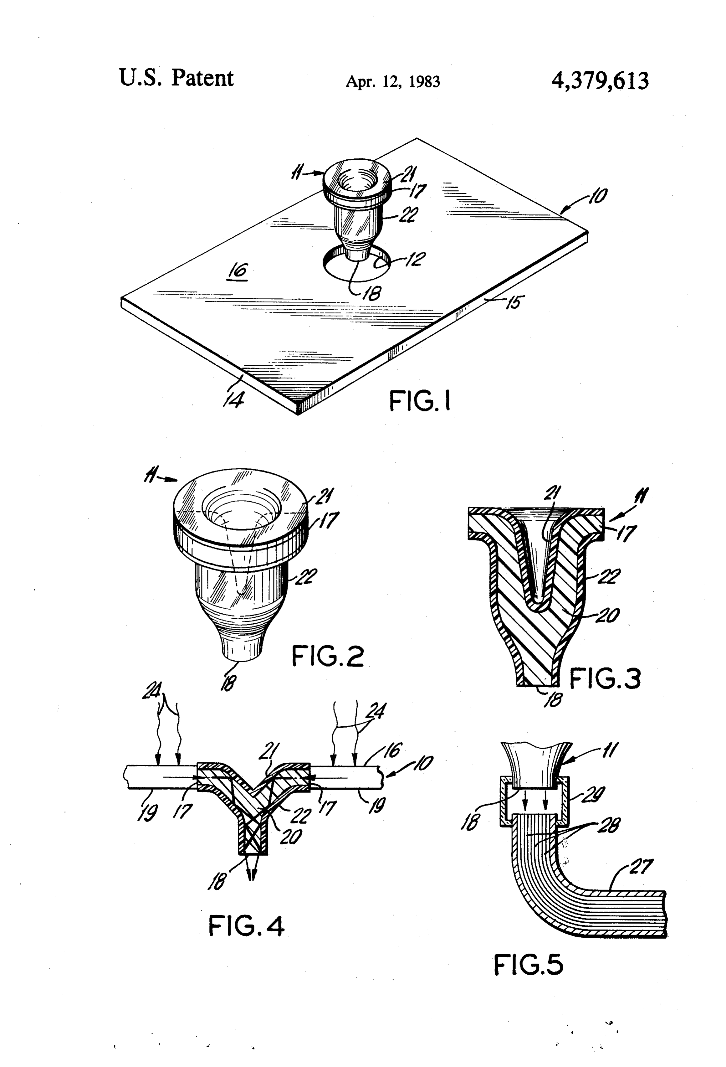
collector and the optical means, prior to assembly and optical coupling thereof.
FIELD OF THE INVENTION FIG. 2 is a schematic prospective view of the pre ferred optical means for transmission of light in accor
The present invention relates to the collection of 5 dance with the present invention.
solar radiation and its transmission in the form of light FIG. 3 is a cross-sectional view of the optical means to a point of use. More particularly, the instant inven of FIG. 2.
tion is concerned with the efficient coupling of a planar FIG. 4 is a cross-sectional view similar to FIG. 3 luminiscent solar collector to optical wave guides. O showing another embodiment of the present invention.
BACKGROUND OF THE INVENTION FIG. 5 illustrates a method for coupling a beam of light from said optical means to a bundle of optical
The economic conversion of solar energy into electri fibers or wave guides for transmission of said light to a cal or thermal energy requires a relatively high solar point of use.
flux impinging on the conversion device. Consequently, there have been numerous attempts to collect the gener 15 DETAILED DESCRIPTION OF THE ally diffused sunlight falling on relatively large areas, INVENTION concentrating it into a small area for more efficient conversion of the radiant energy to a more useful form entThe planar fluorescent solar concentrator of the pres invention with its associated optical means is sche of energy.
One type of solar concentrating device receiving 20 matically
Referring illustrated in FIGS. 1 and 4 of the drawings.
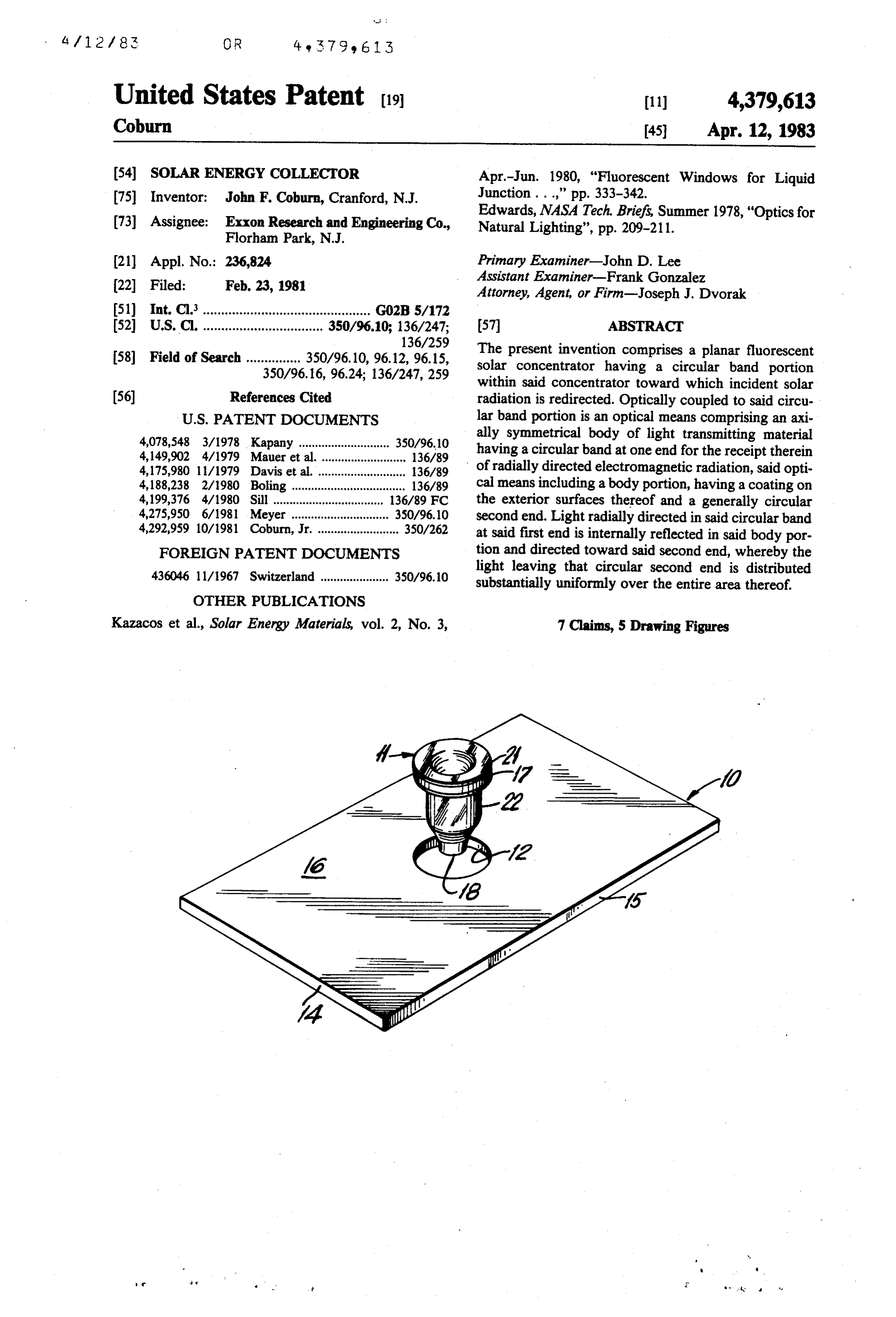
specifically, however, to FIG. 1, and in ac increasing attention consists of a large area of fluores cordance with this invention, a planar fluorescent solar cent material on which solar radiation impinges, and as collector 10 is provided for the receipt of incident solar a consequence thereof, the fluorescent material emits radiation.
radiation which is internally reflected within the collec Planar fluorescent concentrators, of course, are well tor and directed toward a smaller area where it is opti 25 known in the art and consist, for example, of layers of cally coupled, for example, to an energy conversion device, such as a photovoltaic cell. Examples of such dyes on light transparent slabs of material or consist of devices are given in U.S. Pat. No. 4,149,902 and U.S. glass containing fluorescent chelates, certain inorganic ions, or the like.
the photovoltaic device is contiguous with the fluores 30 In accordance with this invention, both sidewalls cent collector. In one embodiment of U.S. Pat. No. (one of which is designated 15 in FIG. 1) and both 4,175,980, however, the photo-voltaic device is not endwalls (one of which is designated 14 in FIG. 1) of contiguous with the fluorescent collector, but is sepa the planar fluorescent concentrator 10 are preferably rated from the concentrator by means of a fiber optic coated with a light reflecting material, such as alumi mechanism. 35 num, silver, and the like. The bottom surface (desig Whatever advantages there may be in devices of the nated as 19 in FIG. 4) of the planar fluorescent concen type disclosed in the above-mentioned patents, there trator 10 is coated with a light reflective material such still remains a need for efficiently joining a large surface as a silver or aluminum mirror, for example. Impor area planar concentrator to a fiber optic bundle or light tantly, fluorescent planar concentrator 10 is provided pipe for transmission of the electromagnetic radiation 40 with at least one internal, substantially circular aperture concentrated in the planar concentrator to a point of defining a substantially circular edge band portion 12. Sc. Light incident on the top surface 16 of the concentrator SUMMARY OF THE INVENTION 10 is concentrated and transmitted toward the edge of band portion 12.
Briefly stated, the present invention comprises a pla 45 As is shown in FIGS. 1 and 4, the solar concentrator nar fluorescent solar concentrator having a circular 10 includes an optical means 11. Optical means 11 is band portion within said concentrator toward which designed to be, and is, optically coupled to the band incident solar radiation is redirected. Optically coupled portion 12 of the planar concentrator 10. Consequently, to said circular band portion is an optical means com the optical means 11 has at its first end a circular band prising an axially symmetrical body of light transmitting 50 portion 17 for mating with and being optically coupled material having a circular band at one end of the receipt to the band portion 12 of concentrator 10. Basically, as therein of radially direction electromagnetic radiation, can be seen particularly in FIGS. 2 and 3, the optical said optical means including a body portion, having a means 11 is formed from an axially symmetrical body 20 coating on the exterior surfaces thereof and a generally of light transmitting material. At the second end of the circular second end. Light radially directed in said cir 55 optical means 11 is provided a substantially circular cular band at said first end is internally reflected in said area for the exit of light being transmitted through the body portion and directed toward said second end, optical means. The body of the optical means 11 is whereby the light leaving that circular second end is provided with a coating 21 extending over the entire distributed substantially uniformly over the entire area top surface of the body 20 and a second coating 22 thereof. extenuing over the outer bottom surface of body 20, The precise characteristics and features of the inven leaving only the annular ring portion 17 and the circular tion will become more readily apparent from the fol apex 18 as the only uncoated portions of the optical lowing detailed description when read in light of the means 11. The coatings 21 and 22 will generally be of accompanying drawings. the same type material, e.g. glass, plastic, etc., and have 65 an index of refraction which is less than the index of
DESCRIPTION OF THE DRAWINGS
refraction of the body material 20, whereby the optical
FIG. 1 is an isometric drawing of one embodiment of means 11 will function substantially as a light pipe or the present invention showing a planar fluorescent solar optical wave guide internally reflecting light entering
Page 4
into the optical means 11 at annular ring 17 and trans What is claimed is:
mitting it so as to exit at area 18 of the optical means 11. 1. A planar fluorescent concentrator having a surface In the particularly preferred embodiment of the present for receipt of incident solar radiation, the improvement invention, the optical means 11 is substantially in the comprising: said planar concentrator having the end form of an inverted bell. 5 walls, side walls and bottom surface coated with a light In the embodiment shown in FIG. 4, however, the reflective material, said concentrator having an aper optical means 11 has a more angular, y-shaped cross ture defining a substantially circular band portion section, as shown therein. within said concentrator; and,
The optical means 11 can be formed from any mate a substantially axially symmetrical light transmitting rial used in the formation of optical wave guides, such 10 body having a first end and a circular light trans as glass, plastic, and the like. It is important in the prac missive second end, said first end having an annular tice of the present invention, however, that the optical ring adapted to mate with and optically coupled to means 11 have a light receiving surface which has an said band portion of said concentrator, said light area substantially identical to the light emitting surface. transmitting body having a coating on the exterior Thus, the area of ring 17 of the device shown in FIGS. 15 surfaces thereof other than said annular ring and 1 and 4 is substantially equal to the area of circle 18 in said circular light transmissive second end the optical means 11. whereby light incident on said planar concentrator As will be readily appreciated, the area of the portion is internally reflected and radially directed toward 12 of the solar concentrator 10 is chosen to be consistent said circulr band, enters said light transmitting with the concentration ratio designed for the collector 20 body and is directed to and exits from said second at its intended use. For example, the greater the concen end of said light transmitting body. tration of light by the collector, the greater the potential 2. The collector of claim 1 wherein the light transmit temperature will be where the light is converted into ting body is substantially in the form of an inverted bell. thermal energy; however, significantly high tempera 25 3. The collector of claim 1 wherein the light transmit tures may not be necessary or desirable in many applica ting body is substantially y-shaped in cross-section. tions, the heating of home water serving as an illustra on4.theThe collector of claim 2 or 3 wherein said coating tion of such application. In these instances then the area of the exterior surface of said light transmitting body is of the ring portion 17 relative to the area of the solar body but having aoflower same type material as said light transmitting index of refraction.
collecting surface of collector 10 could be increased.
In any event, as is shown in FIG 4, incident radiation 5. A solar collector comprising: on the top surface 16 of the planar concentrator 10 is a planar fluorescent concentrator having a top sur directed substantially radially into the optical means 11. face of receipt of solar radiation and having end This is indicated by the arrows. Light that enters into walls, side walls and a bottom surface coated with a light reflective material, said concentrator having the circular band entrance portion 17 of the optical is an aperture therein defining a substantially circular means 11 is internally reflected and results in the trans band portion within said concentrator; and, mission of the light down into the body of the optical an optical wave guide having a first end and a second means 11 and finally outwardly substantially uniformly end, said first end having an annular ring portion through the exit end 18. optically coupled to said band portion of said con As is shown schematically in FIG. 5, bundle 27 of 40 centrtor, said optical wave guide extending down optical wave guides 28 is positioned so as to receive the wardly from said concentrator, the second end of radiation exiting from area 18 of the optical means 11, said wave guide being substantially circular in and mechanical means can be used for optically cou cross-section, whereby solar radiation incident on pling the wave guide bundle 27 to the optical means 11 said top surface of said concentrator is internally for receipt of the radiation emanating from exit 18. For 45 reflected and redirected toward the circular band example, a mechanical sleeve 29 might be employed. of the concentrator, radially enters the optical Other coupling devices known for coupling optical wave guide at the first end and is directed to and wave guides also are useful. exits the second end of the wave guide. The invention has been described in detail with par 6. The collector of claim 5 wherein the optical wave ticular reference to preferred embodiments thereof, but 50 guide is substantially in the form of an inverted bell. will be understood that reasonable variations and modi 7. The collector of claim 5 wherein the optical wave fications are possible without departing from the spirit guide is substantially y-shaped in cross-section. and scope of the invention. k
Provenance
- Collection
- Patents citing this work
- Current assignee
- ExxonMobil Technology and Engineering Co
- Original assignee
- Exxon Research and Engineering Co
- Pages
- 4
- Method
- pdftotext (the PDF's own text layer) + pdftoppm 300dpi page scans
- Patent office record
- patents.google.com →
- Source
- Google Patents citing-documents table
- Inventors
- John F. Coburn; Exxon Research and Engineering Co
- Published
- 1983-04-12
- Transcribed from
- patentimages.storage.googleapis.com →