patent · US4029077
Solar energy collector
14 June 1977
Page 1 — bibliographic record
United States Patent 19 11 4,029,077 Gorniak 45) June 14, 1977 54). SOLAR ENERGY COLLECTOR FOREIGN PATENTS OR APPLICATIONS 653,295 2/1963 Italy ................................... 126/270 76 Inventor: Jerry Gorniak, 2317 E. 43rd St.,
Erie, Pa. 16510 Primary Examiner-Kenneth W. Sprague
Assistant Examiner-James C. Yeung 22 Filed: June 13, 1975 57 ABSTRACT A solar collector having a hollow, pyramidical-shaped (21) Appl. No.: 577,259 body made of insulation material and a fluid conduct ing coil of tubing extending around the inside of the (52) U.S. Cl. ................................ 126/271; 350/167 body. A plurality of sheets of rigid material support (51 Int. C.’............................................ F24, 3/02 alternate layers of liquid and of lenses which focus 58) Field of Search ........... 126/270, 271; 350/167; sunlight onto the liquid and onto the coils of tubing 60/641 thereby heating the liquid. The liquid in the coils is connected in series with the liquid supported on the
sheets so that liquid can be withdrawn from the ends of the coils and passed through a battery for storing the
UNITED STATES PATENTS heat or otherwise supported and stored. The collector 1,672,750 6/1928 Christiansen ...................... 126/271 also includes an infrared absorber. 3,018,313 1/1962 Gattone ............................. 350/167 3,822,692 5, 1973 Demarest ........................ 126/27 12 Claims, 10 Drawing Figures
Seamus
EZZZZZZZZZZZZZZZZ
SNANA
Page 2
Drawing sheet — no readable text.
Page 3
Drawing sheet — no readable text.
Page 4
Drawing sheet — no readable text.
Page 5
Drawing sheet — no readable text.
Page 6
shoulder 44 at the inner edge of the frame 41. The
SOLAR ENERGY COLLECTOR frames 37,38, 39, 40, 41 and 42 are generally rectan gular and open at the center and receive the coils of
REFERENCE TO PRIOR ART copper tubing. Rigid support plates set between the Various solar batteries have been made as shown in 5 frames.
patent numbers 3,104,210; 3,171,403; 3,446,119; The third rigid sheet 15 is supported on the second 3,493,491 and 3,780,722, for example, but none of shoulder 45 and the sheet of water 16 is disposed be these patents show the idea of focusing the sunlight on tween the third sheet 15 and the upper sheet 46. A filler layers of liquid, such as disclosed in the present appli strip 47 extends around the outside of the sheets 15 and cation. 10 46 and forms a closure for the sheet of liquid 16 re
OBJECTS OF THE INVENTION
ceived therebetween. The sheet of liquid 16 can be water, alcohol, mineral oil or any other suitable liquid
It is an object of the invention to provide an im material for absorbing heat from the sun's rays that are proved solar energy collector. V directed on it by lenses 17, or by cooling them by con Another object of the invention is to provide a solar 15 vection. Lenses 17 have a focal length suitable for energy collector that is simple in construction, eco focusing on liquid 16. The sheets 15, 11, 14, 46,48,49, nomical to manufacture, and simple and efficient to 50, 51, and 53 will be made of rigid transparent mate U.S., rial such as glass. The sheets of water 21, 16 will be With the above and other objects in view, the present disposed between the several rigid sheets. The first invention consists of the combination and arrangement 20 lenses 12 and the second lenses 17, third lenses 20, and of parts hereinafter more fully described, illustrated in fourth lenses 23 and fifth lenses 54, will all be made of the accompanying drawing and more particularly conventional lens material such as glass or suitable pointed out in the appended claims, it being under plastic material having the desired characteristics. In stood that changes may be made in the form, size, stead of supporting the lenses on the rigid sheets, the proportions, and minor details of construction without 25 lenses could be molded from a single sheet of plastic departing from the spirit or sacrificing any of the ad with the spaces between them formed in the shape of vantages of the invention. webs. It will be noted that the second lenses 17 of the GENERAL DESCRIPTION OF THE DRAWING collector are supported with the center line through these lenses, extending through the space between the lenses in the layer above them so each layer of lenses
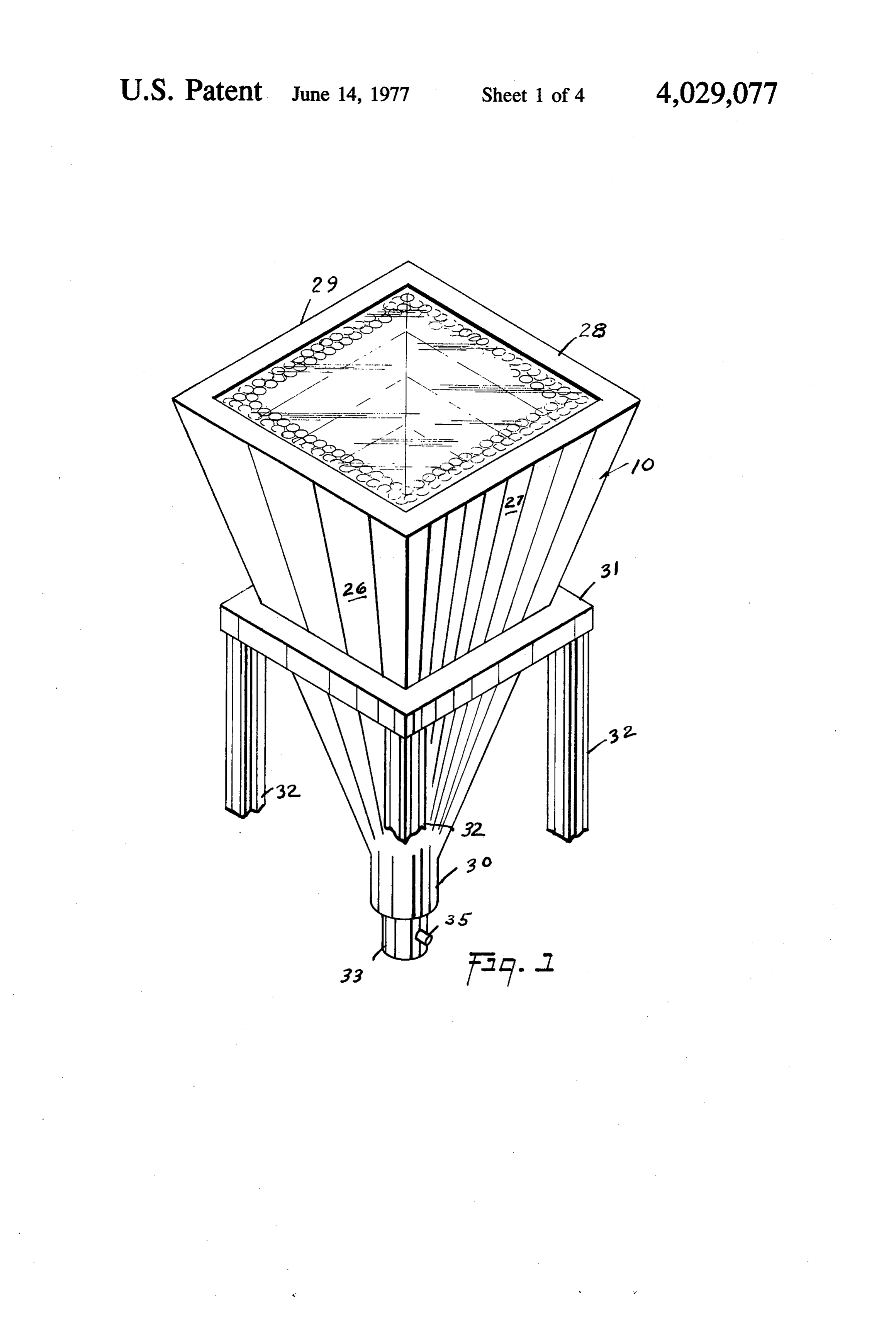
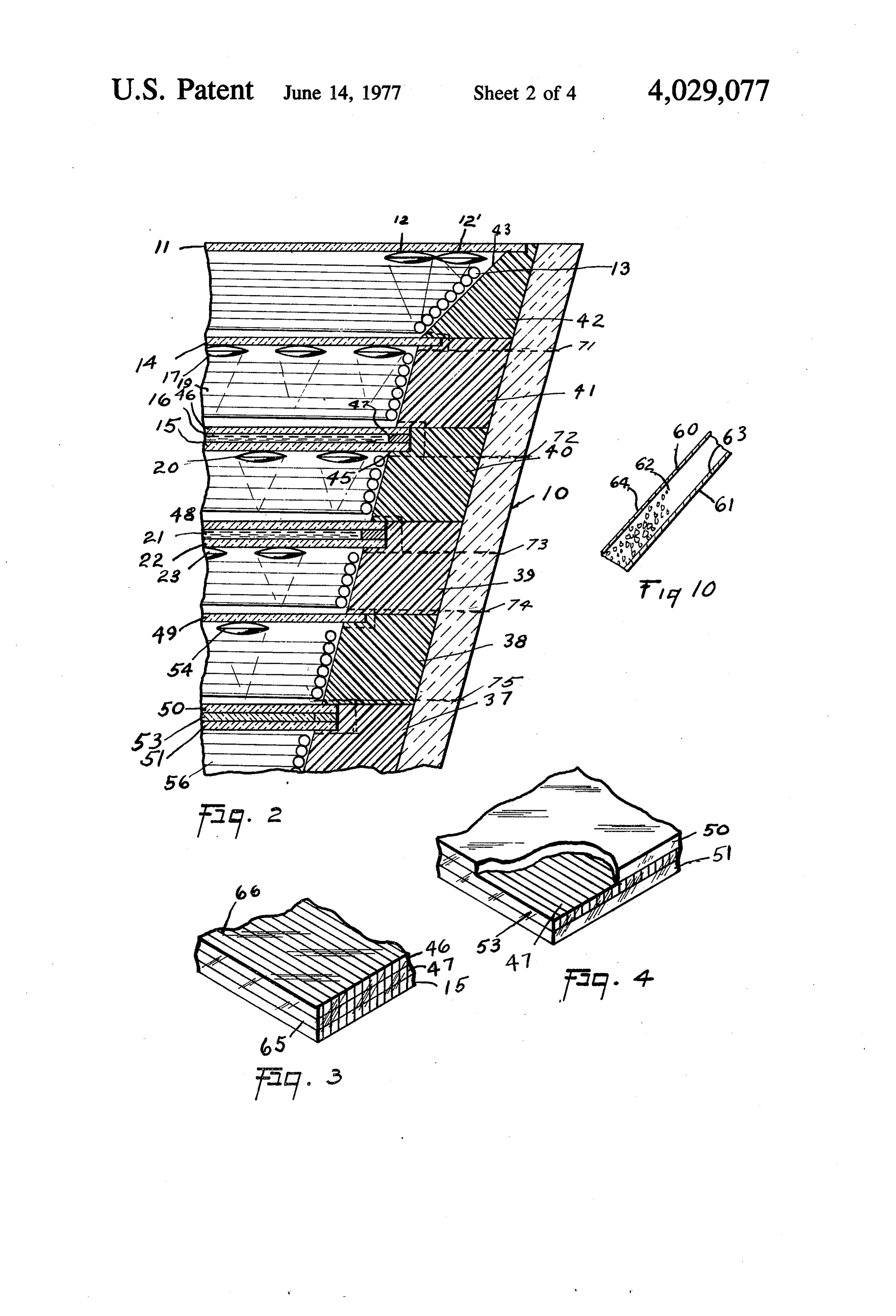
FIG. 1 is an isometric view of the solar collector 30 absorbs according to the invention. some of the sunlight that is missed by the row FIG. 2 is a longitudinal cross-sectional view of the of lenses above.
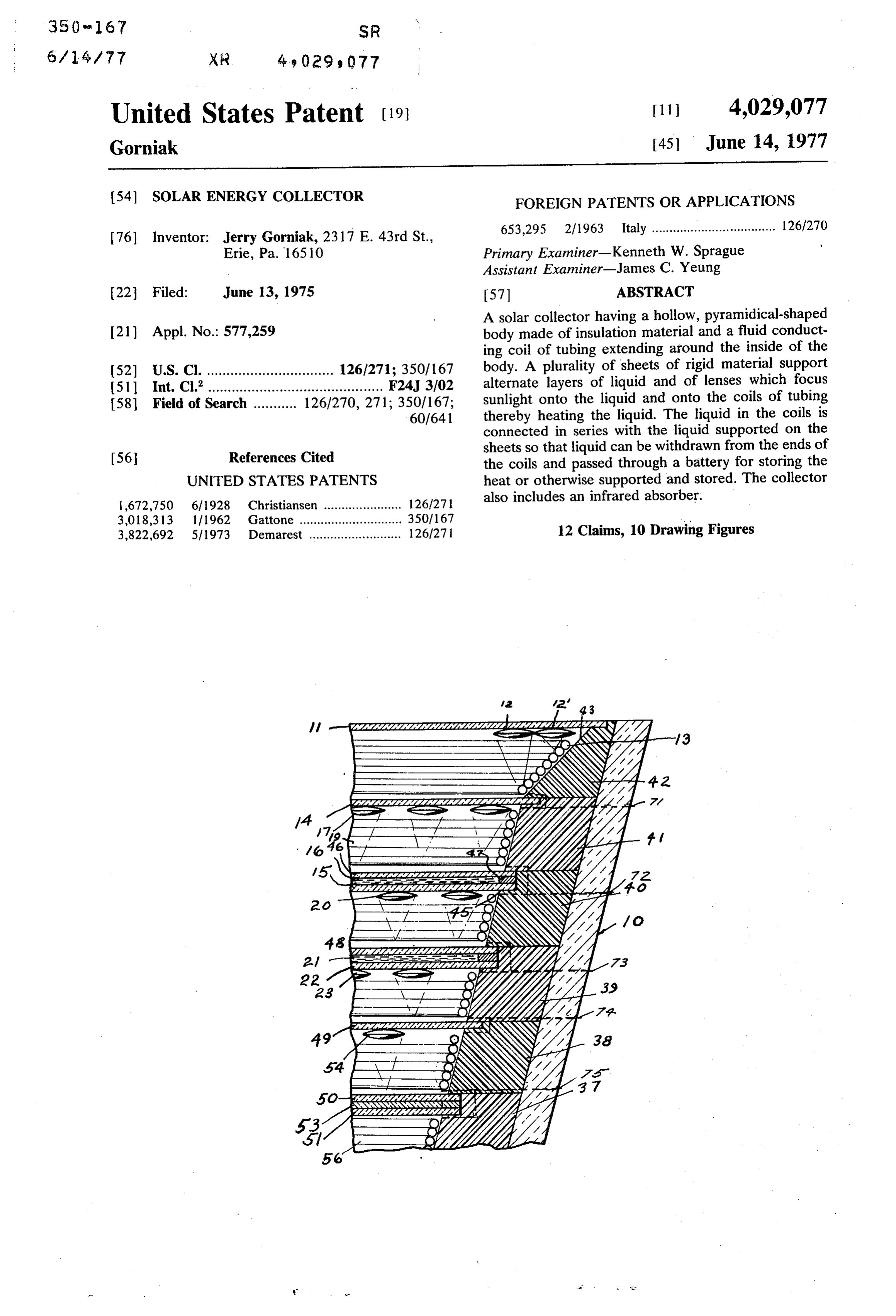
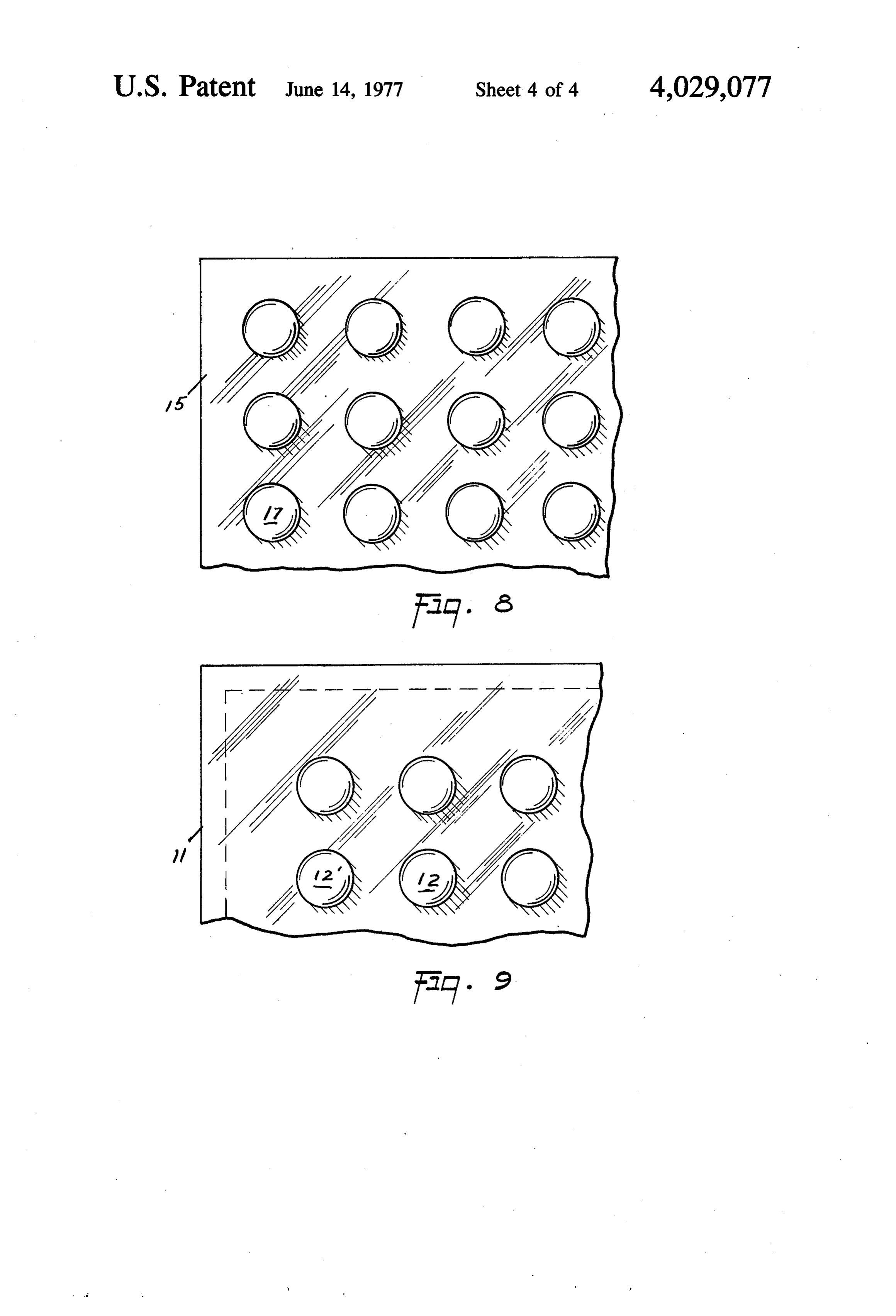
solar collector. The first lenses 12 are supported at their midpoints to FIG. 3 is an enlarged corner view of one of the rigid the first rigid sheet 15 and forms two rows of lenses sheets supporting the liquid with a coil of copper wire 35 adjacent the periphery of sheet 11, primarily focusing wrapped around the sheets, or molded into the sheets. sunlight onto the first coil of tubing 13. The second FIG. 4 is a view similar to FIG.3 showing one corner lenses 17 are fixed to the second rigid sheet 14 at their in an enlarged cross section. midpoints and lenses 17 focus sunlight onto the sheet of FIG. 5 is an enlarged view of one of the coils of the water 16 supported between the rigid sheet 15 and the 40 rigid sheet 46.
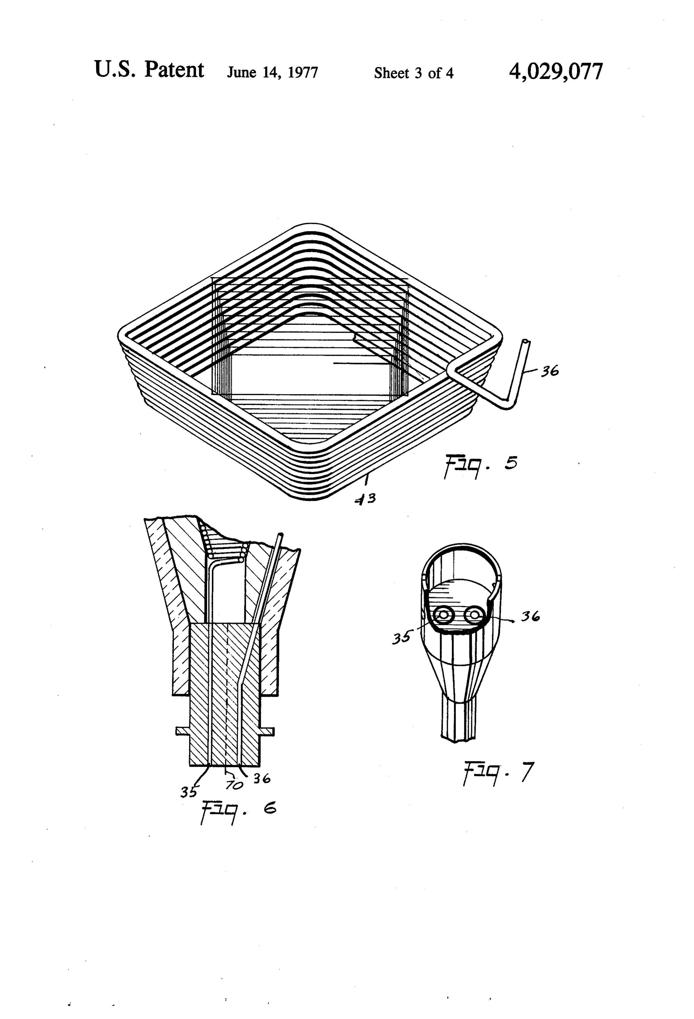
collector showing copper wire supported on it. . . . . . . .. . . . FIG. 6 is a longitudinal cross sectional view of the The third lenses 20 are fixed at their midpoints to the lower end of the collector body. edge of rigid sheet 15 and lenses 20 focus the sunlight FIG. 7 is an enlarged view of the plug in the lower that passes between the spaces between the lenses 17 end of the collector body. onto the sheet of water 21, supported on the fourth FIG. 8 is a top view of the upper rigid sheet showing 45 rigid sheet 22. The second coil 19 rests on the frame 41 the lenses supported according to the invention. between the sheets 14 and 46 and it receives some of FIG. 9 is a view showing the rigid sheet which sup the sunlight from the outer row of lenses 17. The fourth ports a layer of liquid in the collector with lenses sup lenses 23 are fixed to the lower side of the fourth rigid ported on its lower side. sheet 22 and they focus light missed by the sheets FIG. 10 shows a cross sectional view of a head ab 50 above onto the sheet 49 below them. The fifth row of sorbing sheet. lenses 54 are fixed to the lower side of the transparent
DETAILED DESCRIPTION OF DRAWINGS
rigid sheet 49 and they focus sunlight onto the sheet 53, which is wrapped with copper wire and also onto the
Now with more particular reference to the drawings, coil 56 at the lower part of the body. Lenses 20 and 23 the solar collector indicated generally at 10 has a body 55 could be sandwiched between sheets 15 and 46 and that is in a shape of an inverted hollow pyramid and is between sheets 22 and 48 respectively. Rigid sheet 49 supported on the frame 31 having legs 32, for example, can be wrapped with wire like sheets 15, 46, and 47. and the side 26, 27, 28 and 29 defind the pyramidrical It will be noted that the coil 56 is connected in series body having an apex 30 terminating in open end 33. with the terminal 35 and the terminal 35 will be con The body includes support frames 37,38, 39,41 and 42 60 nected in series with the several layers of water in the stacked and supported in it. The upper layer 42 has an body so that the warmed liquid can be removed from inclined surface 43 on which the first copper coil 13 the terminal 36 and passed through a suitable storage rests. The first copper coil 13 receives energy from the battery such as a tank of water or the like, whereby the sun through and around the first two rows of lenses 12 heat can be stored for significant periods of time. and 12", which are attached at their centers to the first 65 The upwardly facing surface 43 of the frame 42 and rigid sheet 11. Lenses 12 and 12' are focused on the the corresponding surface of each of the other frames, coil 13, however; lenses 12" have a shorter focal length is two aluminum sheets 60 and 61 held in spaced rela than the lenses 12. A second rigid sheet 14 rests on the tion to each other by the styrafoam granules 62. The
Page 7
surface of the sheet 60 is black to make a good radia said second lenses being spaced from said sheet of tion absorber and the surface 63 of the aluminum 61 is water a distance substantially equal to the focal of a reflecting surfact thus, the surface 64 will absorb length of said second lenses. infrared radiation and the tubing 13 will be heated 2. The collector recited in claim 1 wherein said first thereby. 5 and second lenses are fixed to said first sheet and said The rigid plates 22 and 48 are wound with copper second sheet of material respectively at the midpoint of wire 65 and 66. This wire may be wound. A row of said lenses.
lenses 12 will have a longer focal length than the row of 3. The collector recited in claim 2 wherein said third lenses 12' so that both lenses 12 and 12' are focused on sheet has a fourth sheet supported thereon and dis the coils 13. All the plates 50,51 and 53 and the plates O posed in fixed relation thereto in defining a space for 22 and 48 are wrapped with wire 47 to give additional said sheet of water therebetween.
heat and cooling absorbing properties to the structure. 4. The collector recited in claim 3 wherein a second The collector can be used for cooling by passing air coil of tubing is disposed around the inside of said through opening 70, and 33 to flow upward through collector between said first sheet of rigid material and bypasses indicated at 71, 72, and 73. These bypasses 15 said second sheet of rigid material. will be made sufficiently large to accommodate the 5. The collector recited in claim 4 wherein a third desired airflow. Louvers can be provided to take air off lens means is fixed to said third sheet, at any desired point 71, 72,73, 74 or 75. a second sheet of water is disposed on said third sheet The collector disclosed herein can be connected to in spaced relation to said second sheet, present heating and cooling equipment. 20 said third lenses being focused on said second sheet The size of the lenses can be varied to accommodate of water.
the desired configuration. 6. The collector recited in claim 5 wherein a fourth The foregoing specification sets forth the invention in rigid transparent sheet supports second sheet of water, its preferred practical forms but the structure shown is and plurality of fourth lenses are fixed to said third capable of modification within a range of equivalents 25 sheet, without departing from the invention which is to be and a third coil is disposed adjacent to periphery of understood is broadly novel as is commensurate with said third sheet.
the appended claims. 7. The collector recited in claim 6 wherein the fourth The embodiments of the invention in which an exclu coil is disposed around the periphery of said fourth sive property or privilege is claimed are defined as 30 rigid sheets.
follows: 8. The collector recited in claim 7 wherein said col 1. A solar collector comprising a fluid path for a lector has a body generally in a shape of an inverted liquid having a plurality of turns disposed generally in a hollow pyramid having an apex and a third coil is dis hollow pyramidial body, posed in said apex for receiving the radiation from said a plurality of first lenses, 35 lenses.
a first sheet means supporting said lenses, 9. The collector recited in claim 8 wherein said body said first lenses having spaced from them a first fluid is open at its apex, path for liquid, and a closure is provided in said open end, said first fluid path for liquid being disposed a dis said closure having terminal tubes connected to said tance substantially equal to the focal length of said 40 tubes in said collector, and connected to said sheet first lenses, of water whereby said tubes and said sheets of means to conduct said liquid from said fluid path to a water are connected in series. heat battery, 10. The collector recited in claim 1 wherein said first said fluid path comprising a first coil of tubing, lenses are arranged in two rows around the periphery of a second sheet of rigid material disposed generally 45 said collector.
parallel to said first sheet, 11. The collector recited in claim 7 wherein a copper and a third sheet of rigid material spaced from said wire is wound around said rigid plates. second sheet generally parallel to said first sheet of 12. The collector recited in claim 11 wherein one material supporting a sheet of water, said layer has at least one row of said lenses attached a plurality of second lenses fixed to said second sheet 50 thereto adjacent to the outside edges thereof. of material to the underside thereof,
Provenance
- Collection
- Cited prior art
- Original PDF
- patentimages.storage.googleapis.com →
- Filed
- 1975-06-13
- Pages
- 7
- Method
- pdftotext (the PDF's own text layer) + pdftoppm 300dpi page scans
- Source
- Google Patents bibliographic record
- Granted
- 1977-06-14
- Inventors
- Jerry Gorniak
- Transcribed from
- patentimages.storage.googleapis.com →