patent · US5934260
Fuel vaporization system for starting an internal combustion engine
10 August 1999
Page 1 — bibliographic record
United States Patent (19) 11 Patent Number: 5,934,260 Gadkaree et al. (45) Date of Patent: Aug. 10, 1999
54 FUEL VAPORIZATION SYSTEM FOR 5,474,049 12/1995 Nagaishi ................................. 123/520 STARTING AN INTERNAL COMBUSTION 5,638,795 6/1997 Hara ........................................ 123/520
ENGINE
75 Inventors: Kishor P. Gadkaree, Big Flats, N.Y.; Primary Examiner-Carl S. Miller Hamid B. Servati, Farmington Hills, Attorney, Agent, or Firm Timothy M. Schaeberle Mich.; Paul M. Then, Glashutten, 57 ABSTRACT
Germany 73 Assignee: Corning Incorporated, Corning, N.Y. Disclosed is cold-Start fuel vapor emission control System for an internal combustion engine having an intake manifold and a fuel tank, comprising the following components: (1) a 21 Appl. No.: 08/943,917 housing for containing an honeycomb adsorber for adsorb 22 Filed: Oct. 3, 1997 ing fuel vapor; (2) a vapor passage for fluidly connecting the housing and the fuel tank; (3) a charging System for mea
Related U.S. Application Data Suring the quantity of adsorbed fuel vapor and for, if 60 Provisional application No. 60/027,900, Oct. 7, 1996. necessary, increasing the amount of adsorbed fuel vapor to (51) Int. Cl." ..................................................... F02M 3704 a level Sufficient to “vapor-only" start the engine; (4) a 52 U.S. Cl. ....................................... 123/520; 123/179.17 purging passage connecting the housing to an intake mani 58 Field of Search ............................... 123/179.17,520, fold for introducing a mixture comprised of the fuel vapor 123/518, 519, 516,521, 198 D and air to the intake manifold. In a preferred embodiment, s s s s the honeycomb adsorber comprises a monolithic, binderleSS 56) References Cited honeycomb structure having a continuous activated carbon phase.
5,474,047 12/1995 Cochard .................................. 123/520 23 Claims, 5 Drawing Sheets
NTERNA
COMBUSTION
ENGINE
Page 2
Drawing sheet — no readable text.
Page 3
Drawing sheet — no readable text.
Page 4
Engine Temp Below To Start Changing Routine Measure Quantity Vapor S Absorbed to Generate Ov
Vapor
Vapor Only Start
Fuel injection
Yes Desorb Absorbed
Vapor Only Start
Engine
Page 5
Drawing sheet — no readable text.
Page 6
Drawing sheet — no readable text.
Page 7
FUEL WAPORIZATION SYSTEM FOR Vapors trapped in the recovery System are recycled into the STARTING AN INTERNAL COMBUSTION intake circuit of the engine. Although this reference dis ENGINE closes a “vapor-only process cold-Start engine System, this System Suffers from a number of disadvantages. (1) electri
This application claims the benefit of U.S. Provisional cally heating the adsorber filter from the outside is likely to Application No. 60/027,900, filed Oct. 17, 1996, entitled result in Slower than industry desired vapor desorption, i.e., Fuel Vaporization System for Starting an Internal Combus a System in which starting of the engine is delayed; (2) tion Engine, by Kishor P. Gadkaree, Hamid B. Servati, and absence of a mechanism in the System to guarantee that there Paul M. Then. is Sufficient vapor available to start the engine; and, (3) this System having a activated carbon packed bed pellet con
BACKGROUND OF THE INVENTION figuration is likely to generate insufficient vapor as a result 1. Field of the Invention the inherent high preSSure drop associated with packed bed The present invention generally relates to an apparatus configurations.
and method for adsorbing fuel vapor and thereafter desorb Notwithstanding the foregoing developments, work has ing and Supplying a Sufficient amount of the vaporized fuel 15 continued to discover and provide new engine Systems not necessary to Start an internal combustion engine using only only capable of meeting the Stricter governmental emission the fuel vapor. Standards but which are also capable of consistently and 2. Description of the Related Art quickly “vapor-only' Starting.
Although catalytic converters are well known for reduc SUMMARY OF THE INVENTION ing oxides of nitrogen (NOx), and oxidizing hydrocarbons and carbon monoxide from automobile exhaust, these reac Accordingly, described herein is a cold-Start fuel vapor tions typically take place after the catalyst has attained its emission control System for an internal combustion engine light-off temperature, at which point the catalyst begins to having an intake manifold and a fuel tank, comprising the convert the hydrocarbons to harmless gases. The typical 25 following components: (1) a housing, having both a vapor catalytic light-off time for most internal combustion engine and an air inlet end, for containing an honeycomb adsorber Systems is around 50 to 120 seconds (generally in the for adsorbing fuel vapor; (2) a vapor passage for fluidly temperature range of 200-350° C.), although the actual connecting the housing and the fuel tank; (3) a charging stem catalytic light-off time for any System depends on various which measures the quantity of adsorbed fuel vapor and factors, including, for instance, the aging of the catalyst. which, if necessary, increases the amount of adsorbed vapor Seventy to almost ninety five percent of hydrocarbon emis to a level Sufficient to “vapor-only start the engine; (4) a Sions from automotive vehicles are emitted during this first purging passage connecting the housing to an intake mani minute, or So, of “cold Start engine operation. AS the fold for introducing a mixture comprised of desorbed vapor Standards relating to emission control of automobiles ized fuel and air to the intake manifold.
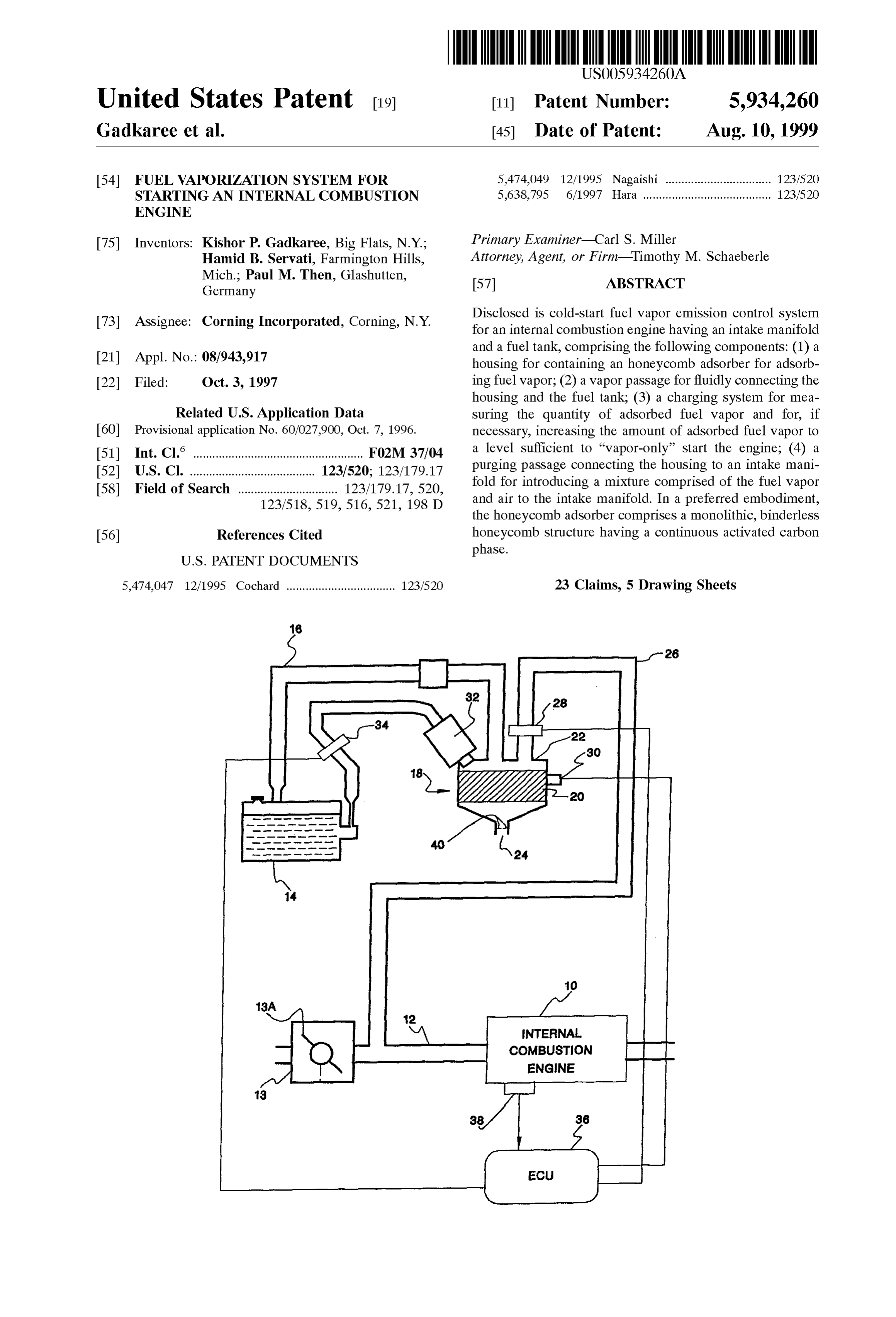
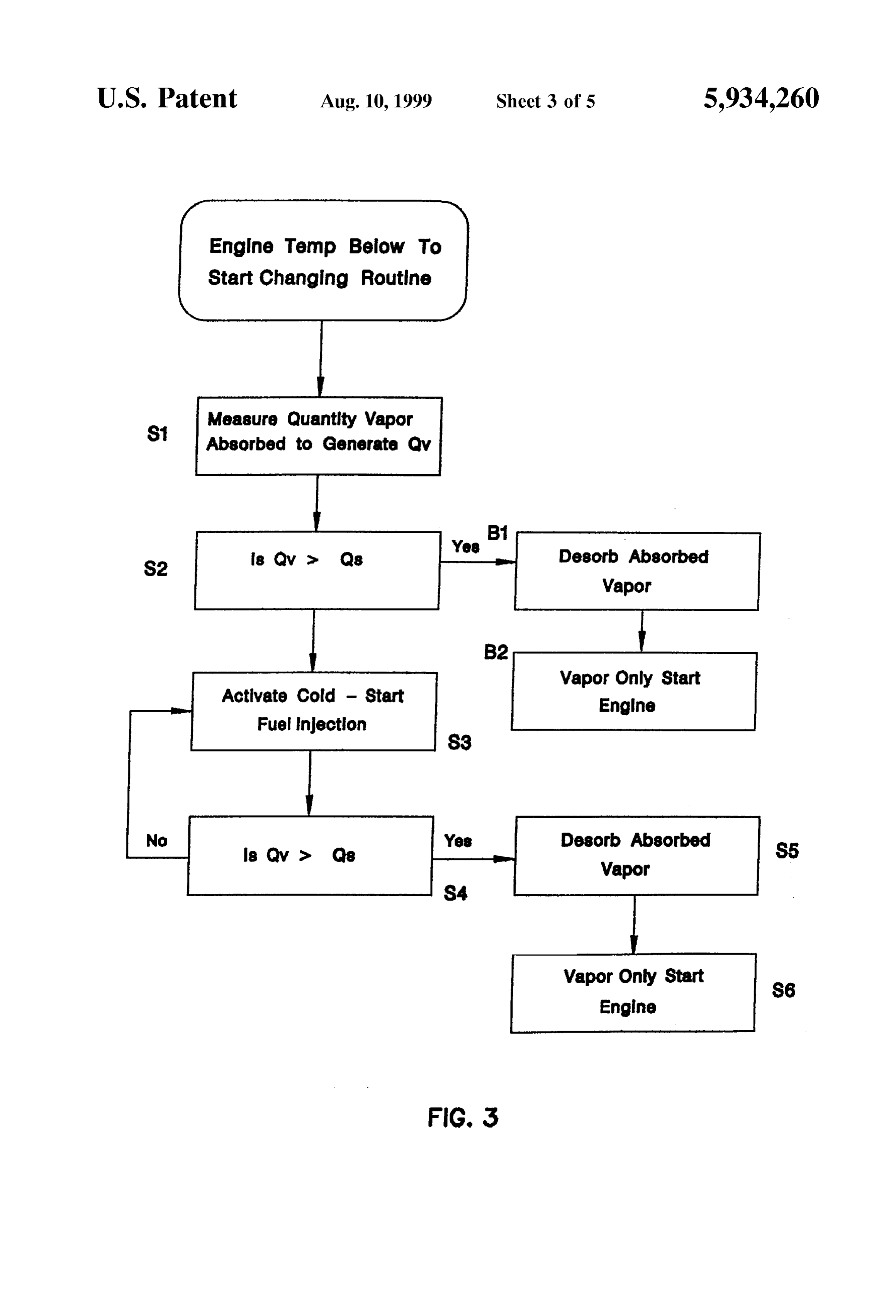
become more Stringent, increasing the effectiveness of auto 35 motive emission control Systems by reducing the amount of BRIEF DESCRIPTION OF THE FIGURES hydrocarbons discharged into the atmosphere during cold FIG. 1 is a block diagram Schematically illustrating the Start has become increasingly important. arrangement of an fuel vapor emission control System for an Cold-start engine Systems utilizing fuel vapor-purging internal combustion engine, according to an embodiment of methods for internal engines are widely known and have 40 the invention;
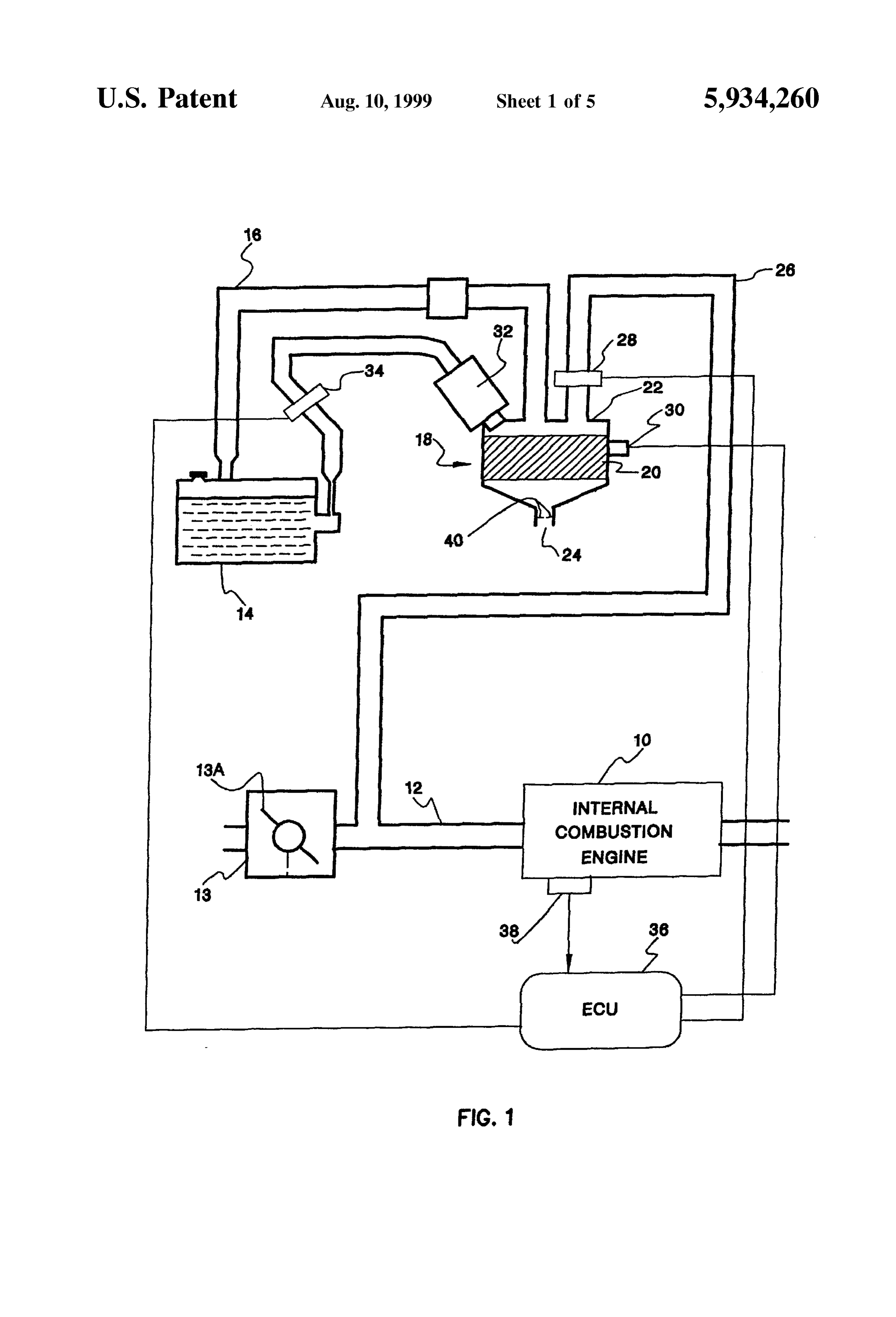
been investigated as System Solutions for reducing cold-start emissions. Generally, these Systems include a canister hav tionFIG. 2 is a bar-graph illustrating increased vapor genera capability of an activated carbon honeycomb adsorber ing activated charcoal or other hydrocarbon adsorbing mate of the instant invention.
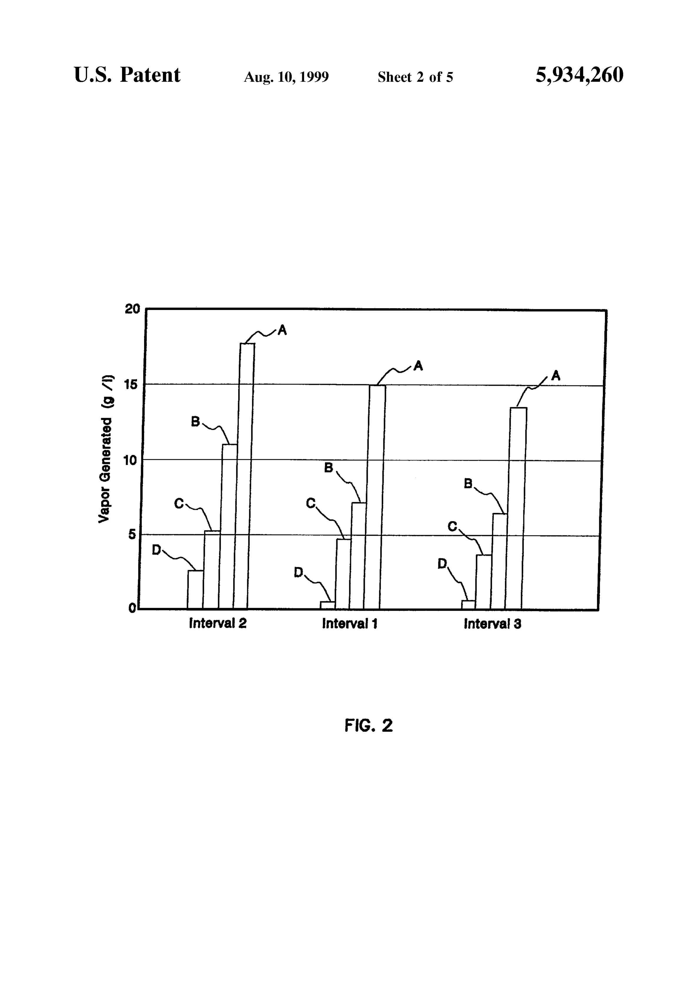
rial for adsorbing fuel vapor generated from the fuel tank in the form of packed pellet bed, a purging passage connecting 45 FIG. 3 is a flow chart illustrating the charging routine between the canister and the intake passage for purging a executed by the inventive System;
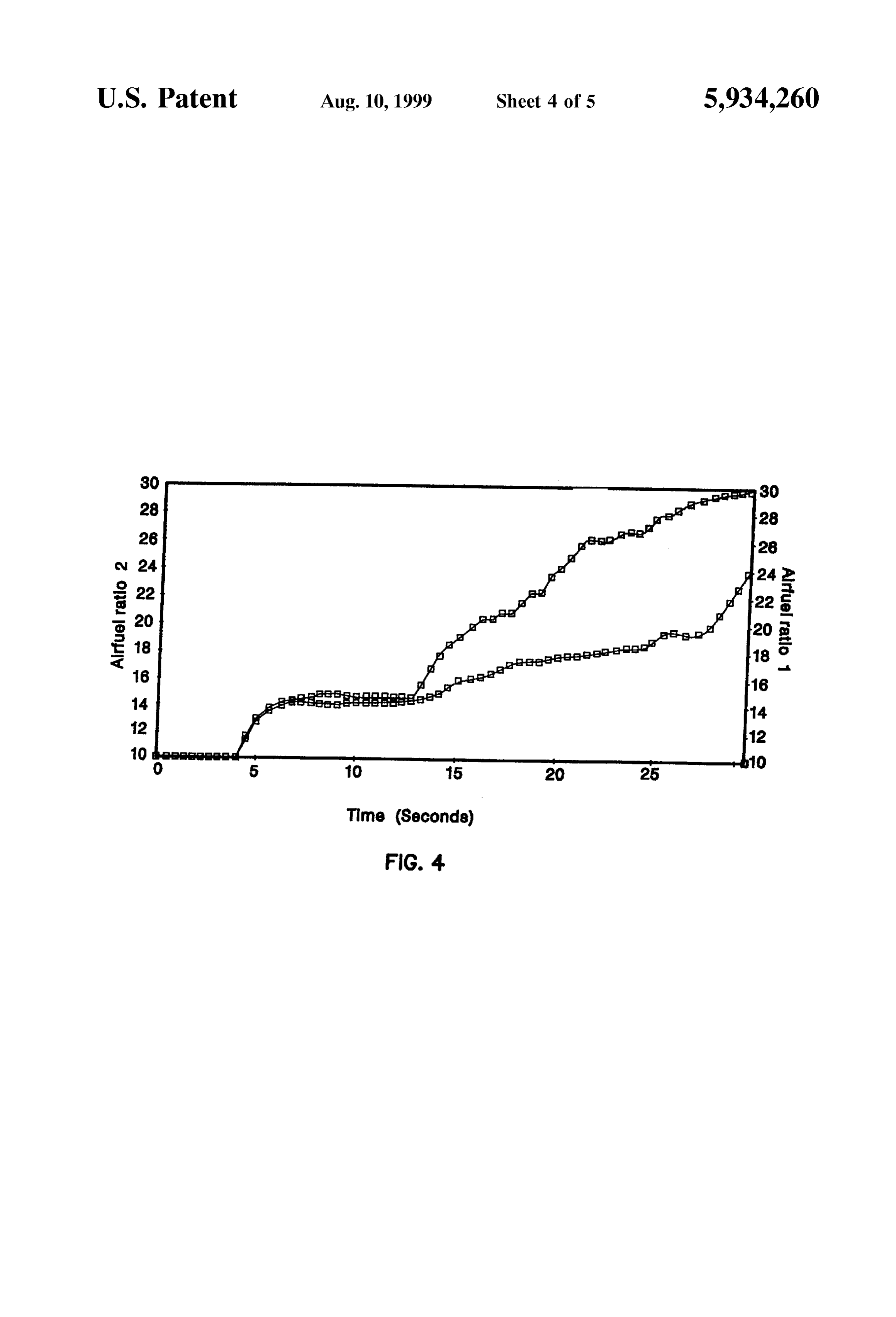
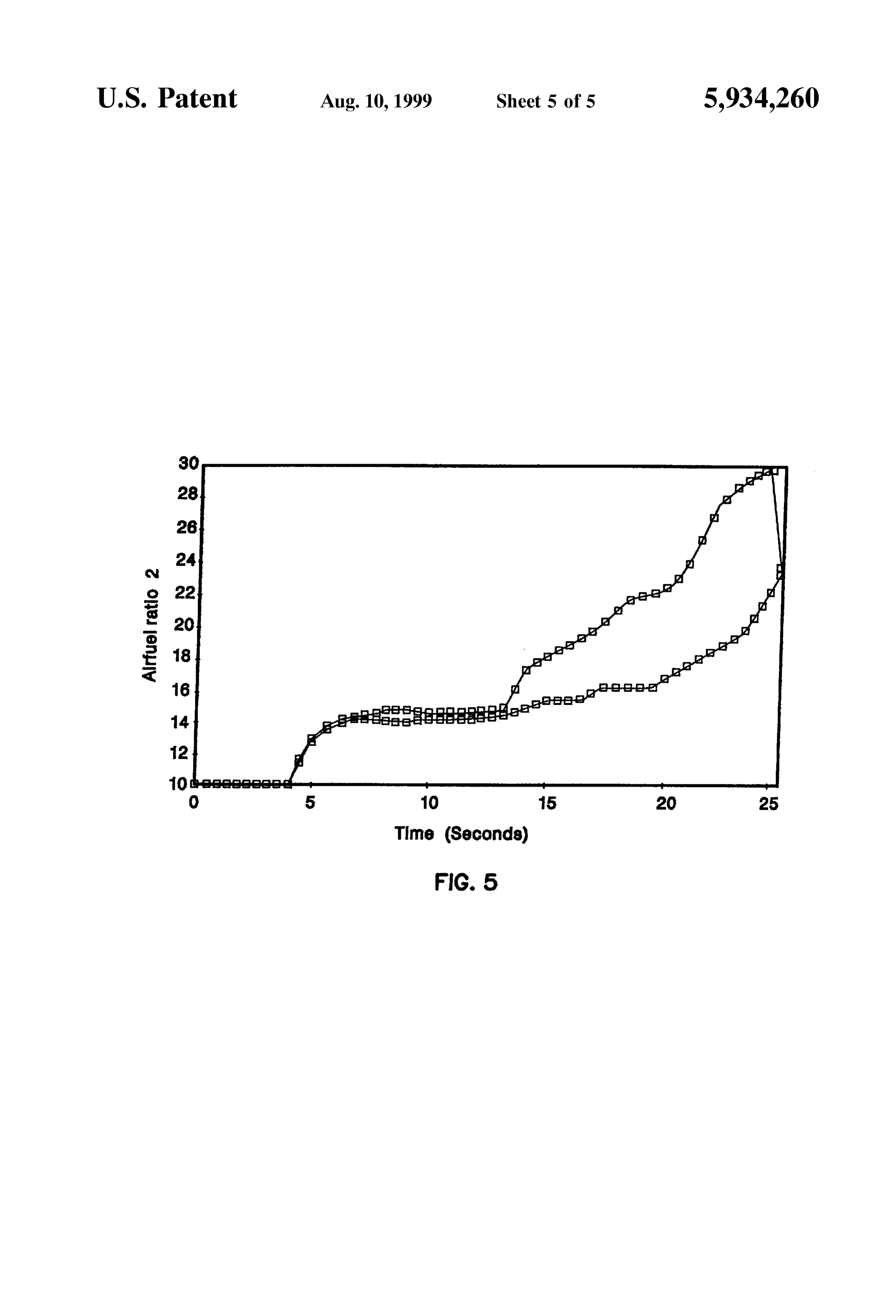
mixture of the fuel vapor and air therethrough into the intake FIGS. 4 and 5 are graphs illustrating the air-to-fuel ratios passage. When Starting the engine in a cold-Start condition of two representative experimental test-run examples. these Systems generally operate to Supply the engine with DETAILED DESCRIPTION OF THE both fuel injected from the fuel injection valves as well as 50 INVENTION fuel vapor purged from the canister. Representative Systems include, Japanese Provisional Utility Model Publication Referring now to FIG. 1, illustrated therein is the arrange (Kokai) No. 3-97560, U.S. Pat. Nos. 5.224,456 (Hosoda et ment of a fuel vapor emission control System capable of al) 5,349,934 (Miyano), and 5,482,023 (Hunt et al.). While Starting an internal combustion engine, according to an these Systems have improved exhaust emission 55 embodiment of the invention. In the figure, reference characteristics, they Still involve injecting a portion of liquid numeral 10 designates an internal combustion engine having fuel into the intake chamber without the fuel being an intake manifold 12 and a fuel tank 14. Fluidly connected Vaporized, which during cold-Start conditions results in to the fuel tank 14, Via a vapor passage 16, is a housing 18 Some part of this liquid fuel attaching to the intake walls and for containing an honeycomb adsorber 20 for adsorbing fuel thereafter being emitted as unburnt hydrocarbons. 60 Vapor. The housing includes a vapor inlet 22 and an air inlet An improvement over the above Standard cold-Start SyS 24 open to ambient air. The system further includes a tems is disclosed in U.S. Pat No. 5,474,047 (Cochard et al.) purging passage 26 connecting housing 18 to intake mani wherein it describes a process for Supplying fuel to an fold 12 possessing a normally closed purge valve 28. When internal combustion engine with controlled fuel injection open, purge valve 28 allows for a mixture comprised of and comprising a controlled fuel vapor recovery System. 65 deSorbed fuel vapor and air to be introduced into intake During cold-Start operating phases of the engine, the fuel manifold 12 upstream of a throttle body 13 and accompa injectors remain inoperative for a given period while the fuel nying throttle valve 13A.
Page 8
The emission System further includes a charging System passes through the honeycomb adsorber desorbing and mix which functions during cold engine conditions to measure ing with the earlier trapped fuel vapor. the quantity of adsorbed fuel vapor and, if necessary, Activated carbon honeycomb adsorbers are especially increase the amount of adsorbed fuel to a level Sufficient to useful in the practice of this invention, preferably in the form “vapor-only' Start the engine. In the construction illustrated of a monolithic, binderless honeycomb structure having a in FIG. 1, the charging system includes a means 30 for continuous activated carbon phase. measuring the quantity of fuel vapor adsorbed and for In one embodiment, the honeycomb adsorber comprises providing an output signal representative. It further features an inorganic monolithic Substrate, preferably cordierite, with a fuel injector 32 connected to a pump 34 for delivering pores extending into the Substrates Surface. The Substrate liquid fuel to the Surface of honeycomb adsorber 20 when further includes a Substantially continuous adherent coating ever the adsorbed fuel output Signal is less than a predeter comprising a layer of activated carbon extending over the mined amount necessary to “vapor-only start the engine. Substrate's Surface and which penetrates into the pores. U.S. The means for measuring the quantity of adsorbed vapor Pat. No. 5,451,444 (Deliso et al.) describes these type of ized fuel may comprise, in the conventional Sense, a vapor activated carbon bodies; this reference hereinafter incorpo Sensor comprised of a pair of electrodes Separated by a 15 rated by reference.
quantity of the adsorbent in the housing through which the In another embodiment, the honeycomb adsorber is made air and vapor mixture passes through during engine opera completely of activated carbon, i.e., a shaped activated tion. The vapor Sensor operates as a capacitance variable as carbon Structure as formed by the binderleSS forming a function of the quantity of vapor adsorbed on the adsorbent method found in U.S. patent application, Ser. No. 08/650, between the electrodes. With the passage of the air and vapor 685. AS disclosed therein the method comprises forming a mixture therethrough the quantity of vapor adsorbed raw material mixture comprising a thermosetting liquid or between the electrodes increases. Solid resin, a carbonizable or inorganic hydrophilic filler, a Another means for determining the amount of vaporized temporary organic binder, and lastly an effective amount of fuel may comprise a System which tracks the number and 25 extrusion aids. The raw material mixture is thereafter times of the purge and Start cycles of the System. These extruded, dried and cured to form a shaped body. cycles, along with parameterS Such as the ambient Furthermore, the shaped body is thereafter be carbonized conditions, the number of times in which the tank is filled, and activated to form an activated carbon honeycomb body. the size of the engine and the fuel vaporization System, Preferably, the shaped activated carbon structure raw would be tracked and monitored to determine the amount of material mixture consists essentially of, in percent by trapped vaporized fuel. weight, of about 2-50% cellulose and/or wood fibers, about An electronic control unit (ECU) 36 controls the opera 30–45% inorganic filler Selected from the group consisting tion of the Starting fuel Supply control System and the of cordierite powder, clay, talc, and combinations thereof, charging System of the present invention. Typically, the ECU about 4-10% organic binder Selected the group consisting of 36 is microprocessor based and receives a plurality of input 35 methylcellulose derivatives, and combinations thereof about Signals from various engine Sensors. These input signals 0-2% lubricant, the balance being phenolic resin. include Signals from vapor Sensor 30, engine temperature Experimentally, it has been determined that the following Sensor 38, as well as other conventional engine Sensors. raw material composition is most preferred, 56.6%, phenolic In a preferred embodiment, the air inlet is sized So that the resin, 22.6% cellulose fiber, 15.1% cordierite, 4.7% appropriate amount of vapor passes through the adsorber 40 methocel, 0.9% sodium Stearate, and 1.0% cobalt acetate. whereby the air/fuel mixture delivered to the engine exhibits The precise size and shape of the activated carbon of the approximately a Stoichiometric ratio. In certain honeycomb bodies, including the appropriate cell size, cell configurations, rather than reducing the size of the air inlet wall size and cell density, is determined on an empirical it may be desirable to restrict the size of the air inlet by basis. The optimal size and shape, and cell features for each including air inlet orifice 40 which is smaller than the 45 System is generally a function of the engine operating diameter of air inlet 24, as well as purging passage 26. AS a conditions and is chosen So as to result in the correct flow direct result of the reduction of air flow and the maintaining and adsorption characteristics. Furthermore, regardless of of the vacuum condition, Standard in the purge passage Size and shape, the design of the honeycomb adsorber itself under normal engine operation, the Stoichiometric fuel-air is Such that it generates the correct amount of vapor and the ratio, and thus engine operation is maintained for a longer 50 proper air-to-fuel ratio for easily starting the vehicle. period of time. This being Said, the ratio of total adsorber Volume-to-open It is contemplated that the air inlet be provided with frontal area is one feature of the honeycomb which is easily orifice capable exhibiting a variable size, for instance, modified to obtain the proper generation of vapor. On the throttle plate. The advantage of this variably sized orifice is one hand, a high ratio will release vapor in a shorter amount that it allows for a system whereby the amount of air, and the 55 of time as the engine draws a large amount of air through the thereby the air/fuel ratio, could be regulated and maintained adsorber honeycomb; however, this is accomplished at the at nearly Stoichiometric, in Spite of changing ambient and expense of “vapor-only' engine run-time. On the other hand, engine conditions. a Smaller ratio will release its vapor over a longer period of The operation of the Starting fuel Supply control System time, but will generate leSS Vapor instantaneously. By cor essentially functions in a Standard way as follows. During 60 rectly choosing this frontal area/volume relationship for the engine operation fuel vapor from fuel tank 14 flows into particular engine and application, the carbon honeycomb Vapor passage 16 and thereafter into housing 18 whereupon will create a more appropriate air-to-fuel ratio. Carbon it is adsorbed by the honeycomb adsorber 20. Fuel vapor honeycomb configurations with the following total adsorber purge occurs when Vapor Sensor 30 exceeds a predetermined Volume-to-open frontal area ratioS have been investigated value whereupon ECU 36 generates an output Signal which 65 and are contemplated to be Suitable for the instant System: operates to open normally closed purge valve 28. During this (1) 5.6 in to 61 in; (2) 22.5 in to 61 in; (3) 45.1 in to 61 Vapor purge, air is drawn through air inlet 24 and thereafter in.
Page 9
S 6
AS mentioned above, the cell geometry is a feature which placed between the air inlet and the carbon honeycomb, is controlled on the activated carbon honeycomb bodies to heats the air entering the housing.
vary the adsorption and desorption rates of the carbon Regardless of the method of heating incorporated, it is honeycomb. Activated carbon honeycomb bodies having desirable that the heating be extremely fast and therefore 150 cells per inch and 20 mil wall thickness, i.e., a configu conveyed to the carbon instantaneously. Furthermore, it was ration having has an open area of 59%, have been Success experimentally determined that only enough heat is required fully used in experimental Systems. By changing this con to Sustain an activated carbon body at a temperature of figuration the airs exposure to wall Surface area would approximately 70 F. room temperature of the experiment. change, e.g. a higher open area honeycomb Structure may be The actual heating would be controlled and initiated by the preferred to more easily and rapidly discharge the vapor. ECU, i.e., the engine temperature Sensor would generate a To illustrate the increased vapor generation capability of Signal below a certain temperature which would necessitate the activated carbon honeycomb and thus its suitability in use of the heating device. The ECU would receive the signal and thereafter operate to cause an electric current to be the instant invention, when compared to packed carbon delivered to the heating device, resulting in the heating of pellet beds, the following experiment was done:
15 the adsorber and an enhancement of the release of the
Two 1" inch diameter, 1%" long honeycomb substrates, hydrocarbons.
Samples A and B, and one carbon pellet packed bed, Sample The advantages of a System utilizing an activated carbon C, of the same dimension, were utilized in the experiment. honeycomb adsorber in the housing over existing Systems Samples A and B, comprised of the aforementioned pre incorporating canister utilizing carbon pellets are as follows: ferred composition, Sample. A not containing the cobalt First, air flow through the honeycomb is much improved, acetate component, were produced according the binderleSS forming method disclosed in U.S. patent application, Ser. i.e., resistance to flow is greatly reduced, when compared to the Systems utilizing carbon pellets in the canister, thereby
No. 08/650,685. Sample C was a standard packed carbon allowing for a quicker removal of the vapors. Secondly, pellet bed like that used in the cold-Start fuel vapor engine utilizing activated carbon honeycomb adsorbers increases Systems previously mentioned in the Background. 25 the uniformity of the adsorption/desorption of the fuel from Each of the three samples were Saturated with gasoline the adsorbent in the housing under a variety of ambient vapor and thereafter subjected to an air flow of 0.5 lb/min conditions. Third, utilizing a flow-through honeycomb per 1 liter of carbon (61 in) for three 20 second intervals; Structure, with its open frontal area and channel Structure, as the Samples were weighed both before and after each opposed to a canister containing activated carbon pellets, interval, the weight loss, equalling the amount of vapor better allows liquid fuel to disperse more rapidly over the generated. The weight loSS, i.e., vapor generated, for each Surface using a simple spray method, Such as a simple fuel Sample and interval was recorded and used to generate the injector System. Lastly, in those applications which may FIG. 2. Referring now to that FIG., it can be seen that the require heating, the activated carbon honeycomb bodies Sample A activated carbon honeycomb body clearly dem have a far greater ability to be uniformly heated electrically onstrated a greater capacity for releasing vapor when com 35 to thereby create vapors at various ambient conditions. pared to the Sample C packed carbon pellet bed Sample. Referring now to FIG. 3, illustrated therein is a flow Specifically, Sample A released 18 grams, 15 grams and 13 diagram of the charging routine utilizing the charging Sys grams of vapor in three Successive 20 Second intervals, tem as mentioned above. Prior to starting the engine 10 while the Sample C released 3 grams, less than 1 gram and under cold-start conditions (i.e., an engine temperature less than 1 gram during the same intervals. 40 below fee cold start temperature T), the first step S1 Ideally, the System should operate whereby the vapor is involves measuring, utilizing, for example a vapor Sensor, generated, i.e., desorbed from the activated carbon honey the quantity of fuel vapor which has been adsorbed by the comb adsorber, without any heating of the adsorber. adsorber. An output signal (Q) representative of this However, under certain conditions, the System may require adsorbed amount is generated and Sent to the ECU, e.g., an enhanced vaporization, preferably achieved by providing the 45 electrical Signal indicative of the amount of adsorbed fuel is System with a means for heating the activated carbon Supplied to the ECU. In other words, this charging routine honeycomb adsorber. An extremely cold engine is one occurs whenever the engine 10 has fallen below that tem condition under which enhanced vaporization is likely to perature which would necessitate “vapor-only' Starting. If neceSSary. there is sufficient vapor (Q>Q) to “vapor-only” start the In those System embodiments which do incorporate a 50 engine the next Step B involves purging the vapor in the heating means in order to enhance the desorption of the manner as described above and thereafter Starting the engine activated carbon honeycomb adsorber it is preferred that the B.
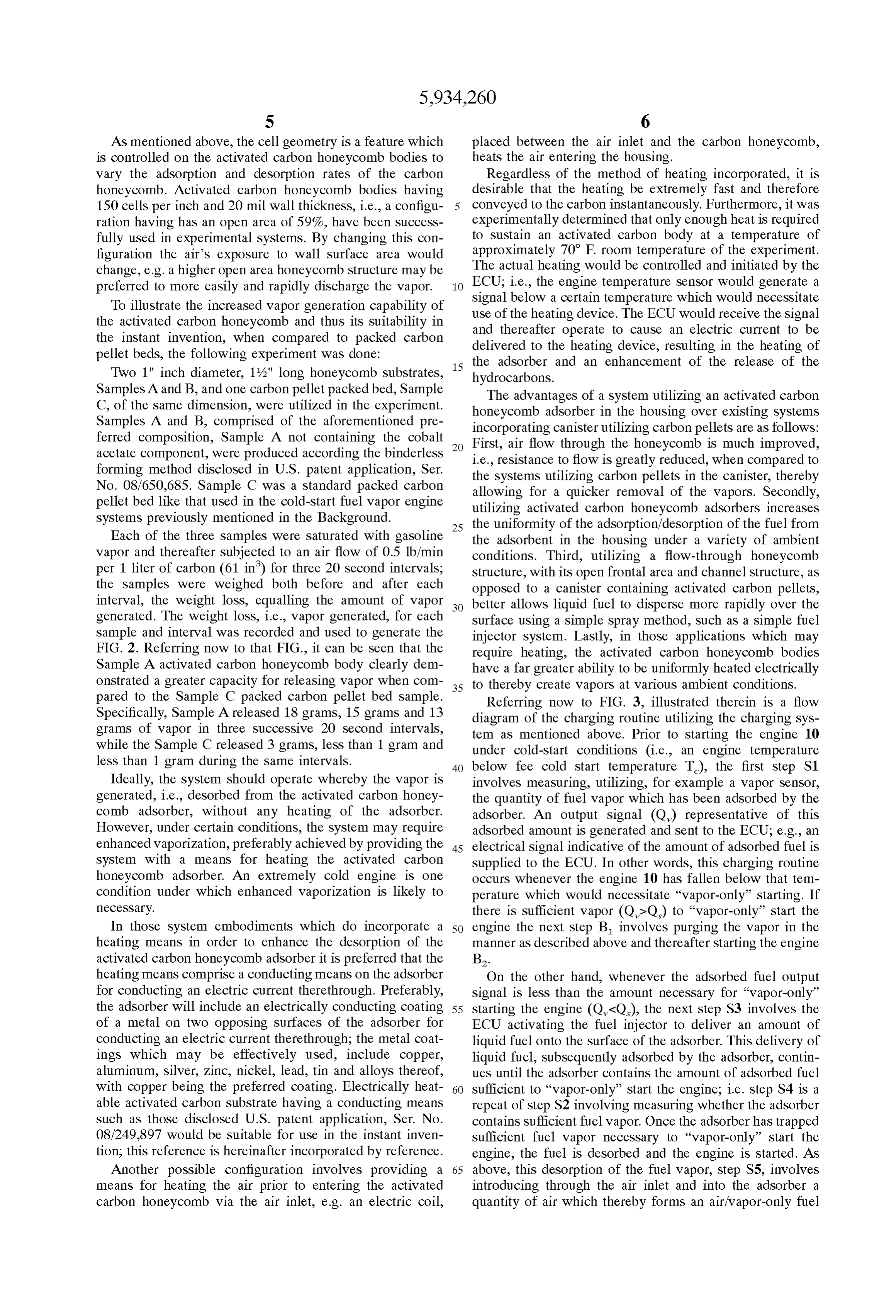
heating means comprise a conducting means on the adsorber On the other hand, whenever the adsorbed fuel output for conducting an electric current therethrough. Preferably, Signal is less than the amount necessary for “vapor-only' the adsorber will include an electrically conducting coating 55 Starting the engine (Q,<Q), the next step S3 involves the of a metal on two opposing Surfaces of the adsorber for ECU activating the fuel injector to deliver an amount of conducting an electric current therethrough; the metal coat liquid fuel onto the surface of the adsorber. This delivery of ings which may be effectively used, include copper, liquid fuel, Subsequently adsorbed by the adsorber, contin aluminum, Silver, Zinc, nickel, lead, tin and alloys thereof, ues until the adsorber contains the amount of adsorbed fuel with copper being the preferred coating. Electrically heat 60 Sufficient to “vapor-only' Start the engine; i.e. Step S4 is a able activated carbon Substrate having a conducting means repeat of Step S2 involving measuring whether the adsorber Such as those disclosed U.S. patent application, Ser. No. contains Sufficient fuel vapor. Once the adsorber has trapped 08/249.897 would be suitable for use in the instant inven Sufficient fuel Vapor necessary to “vapor-only' Start the tion; this reference is hereinafter incorporated by reference. engine, the fuel is desorbed and the engine is started. AS Another possible configuration involves providing a 65 above, this desorption of the fuel vapor, step S5, involves means for heating the air prior to entering the activated introducing through the air inlet and into the adsorber a carbon honeycomb via the air inlet, e.g. an electric coil, quantity of air which thereby forms an air/vapor-only fuel
Page 10
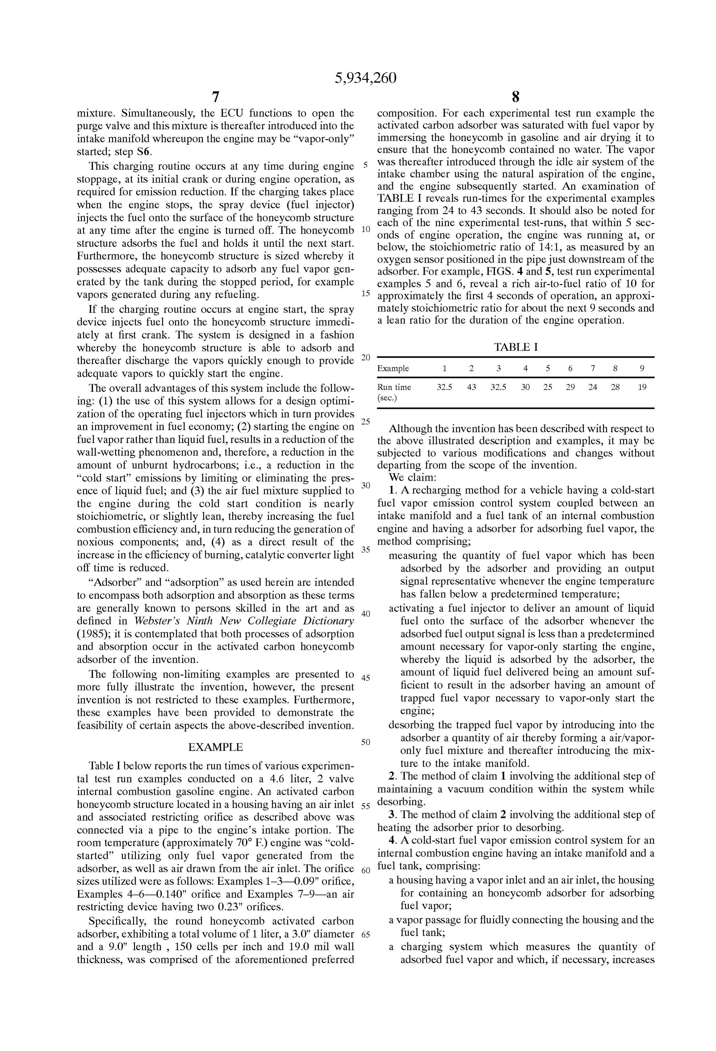
mixture. Simultaneously, the ECU functions to open the composition. For each experimental test run example the purge valve and this mixture is thereafter introduced into the activated carbon adsorber was saturated with fuel vapor by intake manifold whereupon the engine may be “vapor-only' immersing the honeycomb in gasoline and air drying it to started; step S6. ensure that the honeycomb contained no water. The vapor This charging routine occurs at any time during engine was thereafter introduced through the idle air system of the Stoppage, at its initial crank or during engine operation, as intake chamber using the natural aspiration of the engine, required for emission reduction. If the charging takes place and the engine Subsequently started. An examination of when the engine stops, the spray device (fuel injector) TABLE I reveals run-times for the experimental examples injects the fuel onto the Surface of the honeycomb structure ranging from 24 to 43 seconds. It should also be noted for at any time after the engine is turned off. The honeycomb each of the nine experimental test-runs, that within 5 Sec structure adsorbs the fuel and holds it until the next start.
onds of engine operation, the engine was running at, or below, the Stoichiometric ratio of 14:1, as measured by an
Furthermore, the honeycomb structure is sized whereby it oxygen Sensor positioned in the pipe just downstream of the possesses adequate capacity to adsorb any fuel Vapor gen adsorber. For example, FIGS. 4 and 5, test run experimental erated by the tank during the Stopped period, for example examples 5 and 6, reveal a rich air-to-fuel ratio of 10 for Vapors generated during any refueling. 15 approximately the first 4 Seconds of operation, an approxi If the charging routine occurs at engine Start, the Spray mately Stoichiometric ratio for about the next 9 Seconds and device injects fuel onto the honeycomb structure immedi a lean ratio for the duration of the engine operation. ately at first crank. The System is designed in a fashion whereby the honeycomb structure is able to adsorb and TABLE I thereafter discharge the vapors quickly enough to provide Example 1. 2 3 4 5 6 7 8 9 adequate vapors to quickly start the engine.
The overall advantages of this system include the follow Run time 32.5 43 32.5 3O 25 29 24 28 19 ing: (1) the use of this system allows for a design optimi (sec.)
Zation of the operating fuel injectors which in turn provides 25 an improvement in fuel economy; (2) starting the engine on Although the invention has been described with respect to fuel vapor rather than liquid fuel, results in a reduction of the the above illustrated description and examples, it may be wall-wetting phenomenon and, therefore, a reduction in the Subjected to various modifications and changes without amount of unburnt hydrocarbons, i.e., a reduction in the departing from the Scope of the invention. “cold Start emissions by limiting or eliminating the pres We claim:
ence of liquid fuel; and (3) the air fuel mixture Supplied to 1. A recharging method for a vehicle having a cold-start the engine during the cold Start condition is nearly fuel vapor emission control System coupled between an Stoichiometric, or slightly lean, thereby increasing the fuel intake manifold and a fuel tank of an internal combustion engine and having a adsorber for adsorbing fuel vapor, the combustion efficiency and, in turn reducing the generation of noxious components, and, (4) as a direct result of the 35 method comprising;
increase in the efficiency of burning, catalytic converter light measuring the quantity of fuel vapor which has been off time is reduced. adsorbed by the adsorber and providing an output “Adsorber' and “adsorption” as used herein are intended Signal representative whenever the engine temperature to encompass both adsorption and absorption as these terms has fallen below a predetermined temperature; are generally known to perSons skilled in the art and as 40 activating a fuel injector to deliver an amount of liquid defined in Webster's Ninth New Collegiate Dictionary fuel onto the Surface of the adsorber whenever the (1985); it is contemplated that both processes of adsorption adsorbed fuel output signal is less than a predetermined and absorption occur in the activated carbon honeycomb amount necessary for vapor-only starting the engine, adsorber of the invention. whereby the liquid is adsorbed by the adsorber, the The following non-limiting examples are presented to 45 amount of liquid fuel delivered being an amount Suf more fully illustrate the invention, however, the present ficient to result in the adsorber having an amount of invention is not restricted to these examples. Furthermore, trapped fuel vapor necessary to vapor-only Start the these examples have been provided to demonstrate the engine;
feasibility of certain aspects the above-described invention. deSorbing the trapped fuel vapor by introducing into the 50 adsorber a quantity of air thereby forming a air/vapor
EXAMPLE only fuel mixture and thereafter introducing the mix Table I below reports the run times of various experimen ture to the intake manifold.
tal test run examples conducted on a 4.6 liter, 2 valve 2. The method of claim 1 involving the additional step of internal combustion gasoline engine. An activated carbon maintaining a vacuum condition within the System while honeycomb Structure located in a housing having an air inlet 55 deSorbing.
and associated restricting orifice as described above was 3. The method of claim 2 involving the additional step of connected via a pipe to the engine's intake portion. The heating the adsorber prior to desorbing.
room temperature (approximately 70 F) engine was “cold 4. A cold-Start fuel vapor emission control System for an Started' utilizing only fuel vapor generated from the internal combustion engine having an intake manifold and a adsorber, as well as air drawn from the air inlet. The orifice 60 fuel tank, comprising:
sizes utilized were as follows: Examples 1-3-0.09" orifice, a housing having a vapor inlet and an air inlet, the housing Examples 4-6-0.140" orifice and Examples 7-9-an air for containing an honeycomb adsorber for adsorbing restricting device having two 0.23" orifices. fuel vapor;
Specifically, the round honeycomb activated carbon a vapor passage for fluidly connecting the housing and the adsorber, exhibiting a total volume of 1 liter, a 3.0" diameter 65 fuel tank;
and a 9.0" length, 150 cells per inch and 19.0 mil wall a charging System which measures the quantity of thickness, was comprised of the aforementioned preferred adsorbed fuel vapor and which, if necessary, increases
Page 11
the amount of adsorbed fuel vapor to a level sufficient 12. The system of claim 4 wherein the activated carbon to vapor-only start the engine; honeycomb adsorber includes a means for the heating the a purging passage connecting the housing to an intake adsorber.
manifold for introducing a mixture comprised of the 13. The system of claim 12 wherein the means for heating fuel vapor and air to the intake manifold. the activated carbon honeycomb adsorber includes a con 5. The System of claim 4 wherein the charging System ducting means on the adsorber for conducting an electric comprises the following components: current therethrough.
a Sensor for measuring the quantity of fuel vapor adsorbed 14. The system of claim 13 wherein the activated carbon and for providing a output Signal representative;
a fuel injector for delivering liquid fuel to the Surface of honeycomb adsorber includes an electrically conducting the honeycomb adsorber whenever the adsorbed fuel coating of a metal on two opposing Surfaces of the conduct output Signal is less than the predetermined amount ing means for conducting an electric current therethrough. necessary to vapor-only start the engine. 15. The system of claim 14 wherein the metal coating is 6. The system of claim 4 wherein the honeycomb adsorber Selected from the group consisting of copper, aluminum, is a monolithic, binderless honeycomb Structure having a 15 Silver, Zinc, nickel, lead, tin and alloys thereof. continuous activated carbon phase. 16. The system of claim 15 wherein the metal coating is 7. The system of claim 4 wherein the honeycomb adsorber copper.
comprises an inorganic monolithic Substrate with pores 17. The system of claim 4 wherein the honeycomb extending into the Substrates Surface and a Substantially adsorber exhibits a open frontal Surface area-to-volume of continuous adherent coating comprising a layer of activated flow appropriate for delivering the proper fuel to air ratio. carbon extending over the Substrate's Surface and which 18. The system of claim 17 wherein the honeycomb penetrates into the pores. adsorber exhibits open frontal Surface area-to-volume of 8. The system of claim 7 wherein the substrate comprises flow ratio ranging between about 0.05 to 0.75 infin. cordierite.
9. The system of claim 4 wherein the honeycomb adsorber adsorber19. The system of claim 13 wherein the honeycomb comprises a shaped activated carbon Structure. 25 exhibits open frontal Surface area-to-volume of 10. The system of claim 9 wherein the shaped activated flow ratio less than about than 0.4 in/in. 20. The system of claim 13 wherein the honeycomb carbon Structure is made by extruding, drying and curing a raw material mixture about 2-50% cellulose and/or wood adsorber exhibits open frontal Surface area-to-volume of fibers, about 30–45% inorganic filler selected from the group flow ratio less than about than 0.1 in/in. consisting of cordierite powder, clay, talc, and combinations 21. The system of claim 4 wherein the honeycomb thereof, about 4-10% organic binder Selected the group adsorber exhibits a cell geometry whereby the resultant open consisting of methylcellulose derivatives, and combinations area of the adsorber ranges between 25-75%. thereof, about 0–2% lubricant, the balance being phenolic 22. The system of claim 4 wherein the honeycomb resin. adsorber exhibits a cell geometry whereby the resultant open 11. The system of claim 10 wherein the raw material 35 area of the adsorber ranges between 50–75%. mixture consists essentially of, in percent by weight, of 23. The system of claim 4 wherein the air inlet includes 56.6%, phenolic resin, 22.6% cellulose fiber, 4.7% an air restricting inlet orifice. methocel, 0.9% sodium Stearate, 15.1% cordierite and 1.0% cobalt acetate. k k k k k
Provenance
- Collection
- Cited prior art
- Original PDF
- patentimages.storage.googleapis.com →
- Filed
- 1997-10-03
- Pages
- 11
- Method
- pdftotext (the PDF's own text layer) + pdftoppm 300dpi page scans
- Source
- Google Patents bibliographic record
- Granted
- 1999-08-10
- Inventors
- Kishor P. Gadkaree; Hamid B. Servati; Paul M. Then; Corning Inc
- Transcribed from
- patentimages.storage.googleapis.com →