patent · US4324227
Solar heat collecting panel
13 April 1982
Page 1 — bibliographic record
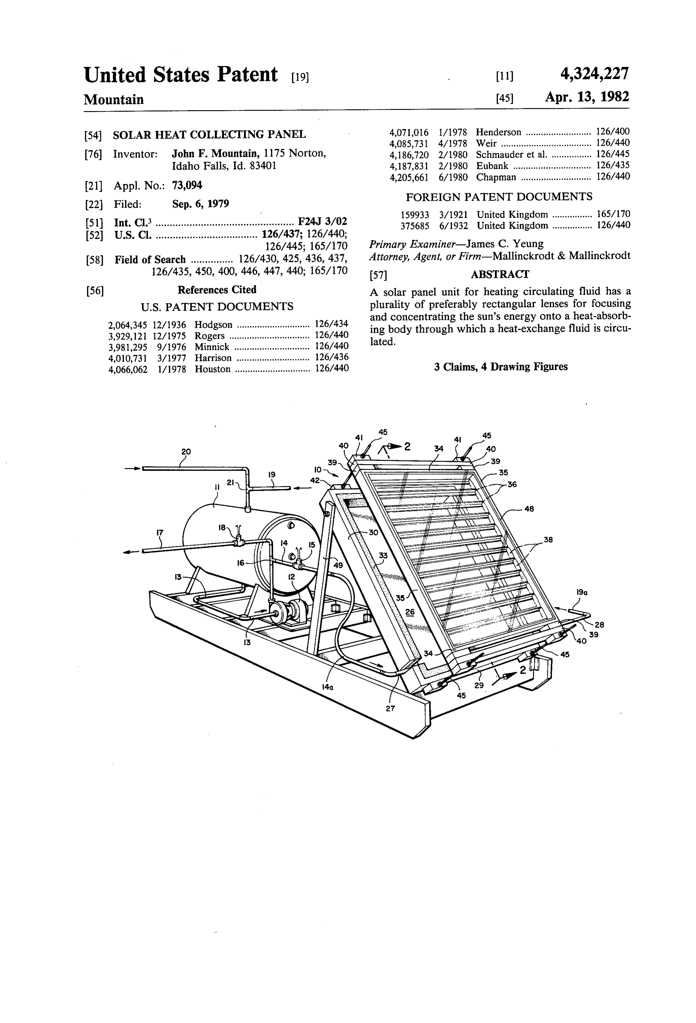
United States Patent (19) 11) 4,324,227 Mountain 45 Apr. 13, 1982
54 SOLAR HEAT COLLECTING PANEL 4,071,016 1/1978 Henderson .......................... 126/400 4,085,731 4/1978 Weir................. ... 126/440 76 Inventor: John F. Mountain, 1175 Norton, 4,186,720 2/1980 Schnauder et al. ... 126/445 Idaho Falls, Id. 83401 4,187,831 2/1980 Eubank ............ ... 126/435 4,205,661 6/1980 Chapman ............................ 126/440
22 Filed: Sep. 6, 1979 FOREIGN PATENT DOCUMENTS
51) Int. Cl.................................................. F24J 3/02 375685 6/1932 United Kingdom................ 126/440 52 U.S. Cl. .................................... 126/437; 126/440;
58) Field of Search ............... 126/430, 425, 436, 437, Attorney, Agent, or Firm-Mallinckrodt & Mallinckrodt 126/435, 450, 400, 446, 447, 440; 165/170 57 ABSTRACT 56) References Cited A solar panel unit for heating circulating fluid has a
2,064,345 12/1936 Hodgson ............................. 126/434 and concentrating the sun's energy onto a heat-absorb 3,929,121 12/1975 Rogers ....... . 126/440 ing body through which a heat-exchange fluid is circu 3,981,295 9/1976 Minnick ..... 126/440 lated.
4,010,731 3/1977 Harrison ... 126/436 4,066,062 1/1978 Houston .............................. 126/440 3 Claims, 4 Drawing Figures
Page 2
Drawing sheet — no readable text.
Page 3
S. N82 A44121.411-41214-1214 s
23 SEZZZZZZZZRS 25E
NNNS
3O 33 26 23 24 24 26 33 Q n Sks
X SSA AAAAAAAAYASS SaaS ASSAs. SAS SaaaaaaS
25o 25o 3 25 32 F.G. 4 25d 25 26b
Page 4
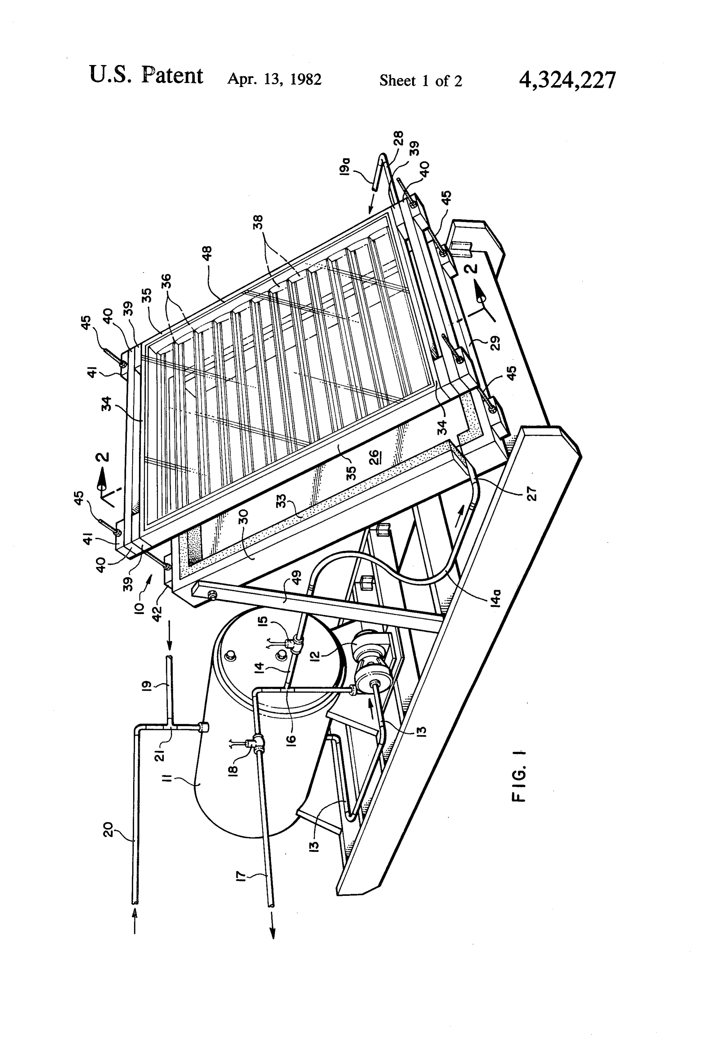
FIG. 1 is a pictorial view of a heat collection and
SOLAR HEAT COLLECTING PANEL storage system according to the invention showing a pump and storage tank as well as the solar panel unit;
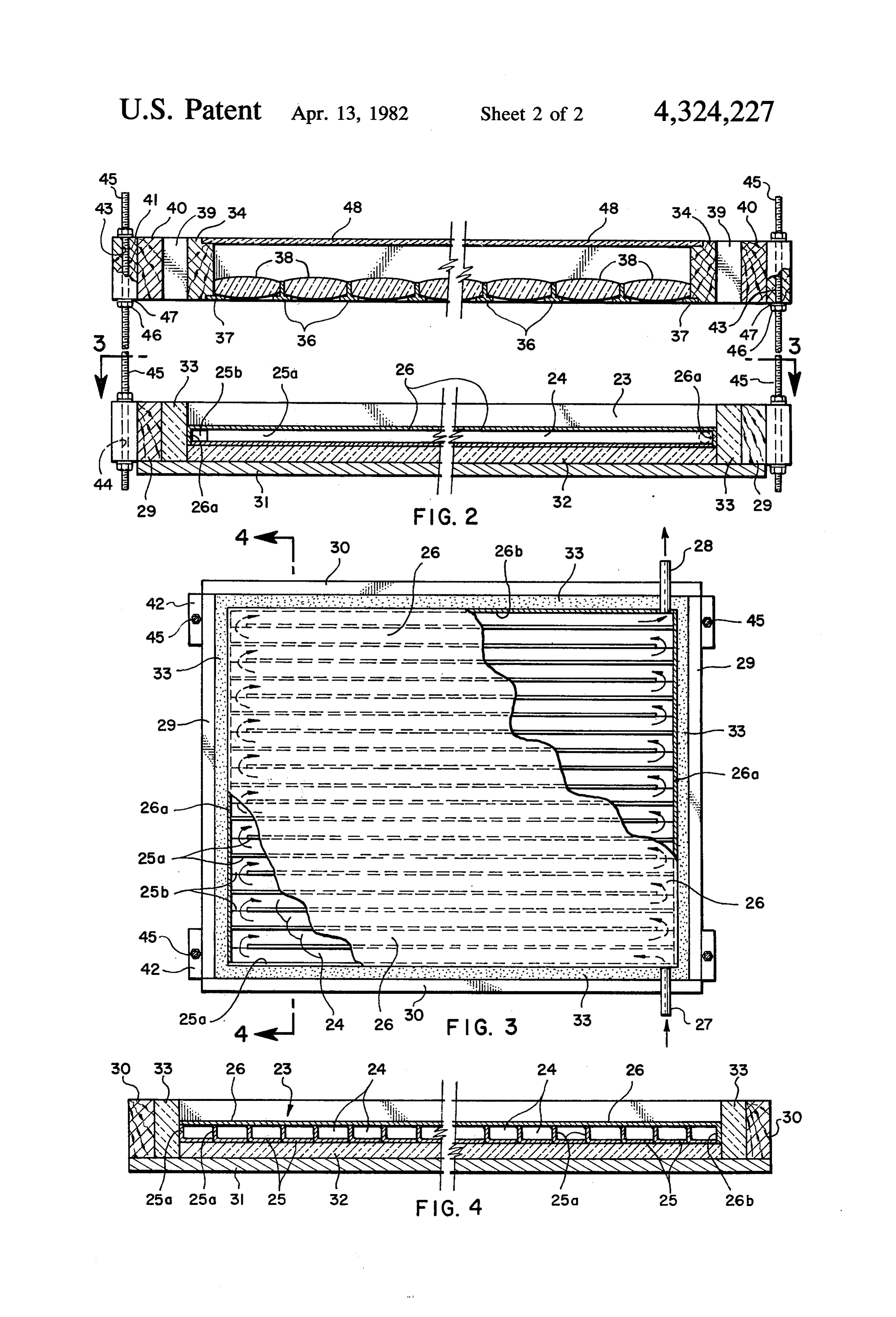
BACKGROUND OF THE INVENTION FIG. 2, a vertical section through the solar panel unit 1. Field: of the invention, taken on line 2-2 of FIG. 1 and drawn The invention is in the field of panels for collecting to a larger scale;
solar energy in the form of heat and transferring it to a andFIG. 3, a top plan view of the heat-absorbing body heat exchange fluid for either immediate use or for and supporting structure, taken on line 3-3 of FIG. 2 drawn to a smaller scale; and storage for future use. 10 FIG. 4, a vertical section taken through the heat 2. State of the Art absorbing body and supporting structure on line 4-4 of During the last several years, interest in solar energy FIG. 3 and drawn to the scale of FIG. 2. has increased enormously and there are many designs for panels for collecting heat energy from the sun and DETAILED DESCRIPTION OF THE transferring such collected heat energy to a heat ex 15 ILLUSTRATED EMBODIMENT change fluid for immediate use or from which the heat The solar heating system illustrated in FIG. 1 com is extracted for storage. prises a solar panel unit 10 for heating a circulating Most present panels for absorbing solar heat energy fluid, a fluid storage tank 11, a fluid pump 12, and piping contain a heat absorbing material which is exposed to between the pump, storage tank, and solar panel unit for direct sunlight and over, around, or through which, a 20 circulation of fluid. Fluid is drawn from tank 11 heat exchange fluid is passed to absorb heat therefrom. through pipe 13 by pump 12. Fluid from pump 12 is Such panels absorb energy from direct incidence of the forced into pipe 14, through which, if valve 15 is open, sun's rays and are thus somewhat limited in the temper it is directed to solar panel unit 10 for circulation there ature they can obtain and in their efficiency. Such pan through. A tee 16 in pipe. 14 provides connection to pipe els do not utilize means for concentrating or magnifying 25 17, through which, if valve 18 is open, fluid is provided the sun's energy. to the location where such fluid is to be used. This may A heat collecting panel that utilizes means for magni be to a heat exchange unit in a forced air furnace, a radiator heating system, a heat exchange unit in a hot fying the sun's energy is illustrated in U.S. Pat. No. water 4,071,016 which shows a panel of triangular cross sec 30 where tank, the or to various other types of equipment heated fluid may be advantageously used.
tion having a series of magnifying glasses arranged to Fluid from the solar panel unit 10 is circulated back to focus the sun on aheat absorbing material over which a storage tank 11 through pipe 19. Fluid that has been stream of air is blown in order to absorb the heat from used by the furnace or other item is returned to tank 11 the heat-absorbing material. The panel structure is es through pipe 20 which interconnects with pipe 19 at tee sentially air tight, so that the air blown into the chamber 35 21.
exits through a hot air duct and is then used. Valves 15 and 18 are preferably electrically con All prior art systems leave much room for improve trolled valves so that they can be controlled remotely ment in the amount of energy collected and in the effi and automatically. Valve 15 will be open at any time ciency of such collection. that enough energy from the sun is striking the solar SUMMARY OF THE INVENTION 40 panel unit to make the temperature of the fluid leaving the unit through pipe 19 greater than the fluid entering
According to the invention, a solar panel unit for the unit through pipe 14, i.e. the fluid leaving storage heating circulating fluid includes a plurality of lenses tank 11. This determination will preferably be made for focusing and concentrating the sun's energy onto a automatically by temperature sensors in the output pipe heat-absorbing body. An enclosed channel passes. 45 19 from the panel unit 10 and either in the storage tank through the heat-absorbing body and heat exchange 11 or in pipe 13 leading therefrom and by a comparitor fluid is passed through such channel. Structure is pro to which the outputs of the temperature sensors are vided for supporting the heat-absorbing body and for connected. Temperature sensors and comparator units supporting the lenses in such a manner that sunlight are well known, form no part of applicant's invention, striking the lenses is focused upon the heat-absorbing 50 and are thus not described in detail. Valve 18 will be body. Means are also provided for positioning the panel open at any time heated fluid is needed by the equip unit so that sunlight falls upon the lenses during normal ment in which such fluid is utilized and may be con daylight hours. - trolled by, for example, a thermostat in a building to be In one arrangement of the invention, the solar panel is 55 heated or a thermostat in a water heater. Pump 12 will associated with a heat exchange fluid storage tank con both be controlled so that it operates only when either one or taining heat storage material, such as pieces of granite from of valves 14 and 18 are open to allow fluid flow the tank.
rock and with piping and a pump so that the heat ex Although solar panel unit 10, storage tank 11, and change fluid is pumped from the tank through the heat pump absorbing body and back into the tank, or so that the 60 a frame1222,aretheillustrated various as located together as a unit on components of the system could heat exchange fluid may be circulated from either the be separated and placed at various locations. tank or the heat-absorbing body for immediate use, such heat loss, it is preferred that tank 11 and allTo reduce piping be as in a furnace or hot water heater. insulated, such as by being covered by a layer of foam THE DRAWINGS. insulation. It is also preferred that storage tank 11 have 65 a capacity of at least 300 gallons, and that about half of
In the accompanying drawings, which represnt the the volume of the tank be taken up by pieces of granite best mode presently contemplated for carrying out the or other material which have high heat storage capac invention: ity.
Page 5
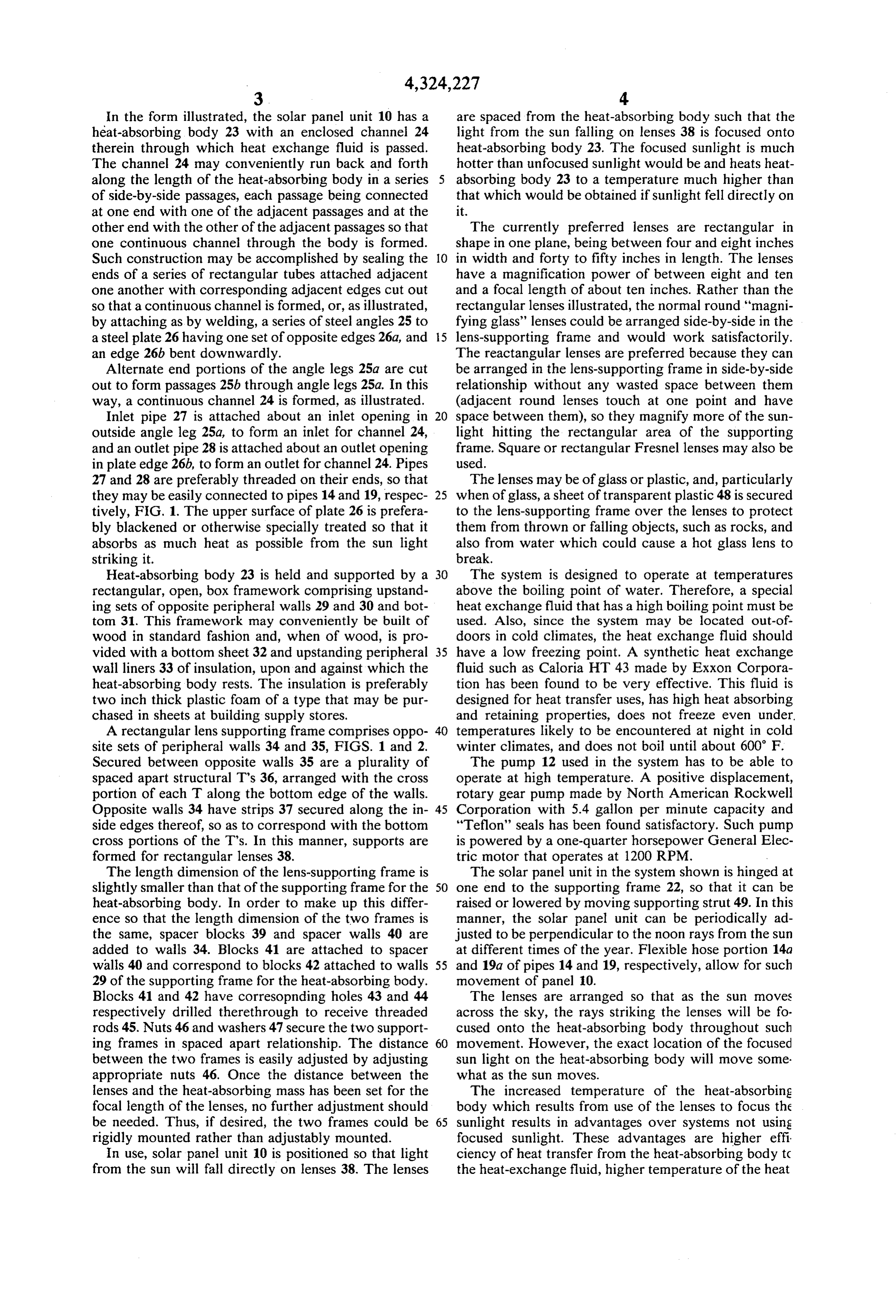
In the form illustrated, the solar panel unit 10 has a are spaced from the heat-absorbing body such that the heat-absorbing body 23 with an enclosed channel 24 light from the sun falling on lenses 38 is focused onto therein through which heat exchange fluid is passed. heat-absorbing body 23. The focused sunlight is much The channel 24 may conveniently run back and forth hotter than unfocused sunlight would be and heats heat along the length of the heat-absorbing body in a series absorbing body 23 to a temperature much higher than of side-by-side passages, each passage being connected that which would be obtained if sunlight fell directly on at one end with one of the adjacent passages and at the it.
other end with the other of the adjacent passages so that The currently preferred lenses are rectangular in one continuous channel through the body is formed. shape in one plane, being between four and eight inches Such construction may be accomplished by sealing the O in width and forty to fifty inches in length. The lenses ends of a series of rectangular tubes attached adjacent have a magnification power of between eight and ten one another with corresponding adjacent edges cut out and a focal length of about ten inches. Rather than the so that a continuous channel is formed, or, as illustrated, rectangular lenses illustrated, the normal round "magni by attaching as by welding, a series of steel angles 25 to fying glass' lenses could be arranged side-by-side in the a steel plate 26 having one set of opposite edges 26a, and 5 lens-supporting frame and would work satisfactorily. an edge 26b bent downwardly. The reactangular lenses are preferred because they can Alternate end portions of the angle legs 25a are cut be arranged in the lens-supporting frame in side-by-side out to form passages 25b through angle legs 25a. In this relationship without any wasted space between them way, a continuous channel 24 is formed, as illustrated. (adjacent round lenses touch at one point and have Inlet pipe 27 is attached about an inlet opening in 20 space between them), so they magnify more of the sun outside angle leg 25a, to form an inlet for channel 24, light hitting the rectangular area of the supporting and an outlet pipe 28 is attached about an outlet opening frame. Square or rectangular Fresnel lenses may also be in plate edge 26b, to form an outlet for channel 24. Pipes used.
27 and 28 are preferably threaded on their ends, so that The lenses may be of glass or plastic, and, particularly they may be easily connected to pipes 14 and 19, respec 25 when of glass, a sheet of transparent plastic 48 is secured tively, FIG. 1. The upper surface of plate 26 is prefera to the lens-supporting frame over the lenses to protect bly blackened or otherwise specially treated so that it them from thrown or falling objects, such as rocks, and absorbs as much heat as possible from the sun light also from water which could cause a hot glass lens to striking it. break.
Heat-absorbing body 23 is held and supported by a 30 The system is designed to operate at temperatures rectangular, open, box framework comprising upstand above the boiling point of water. Therefore, a special ing sets of opposite peripheral walls 29 and 30 and bot heat exchange fluid that has a high boiling point must be tom 31. This framework may conveniently be built of used. Also, since the system may be located out-of wood in standard fashion and, when of wood, is pro doors in cold climates, the heat exchange fluid should vided with a bottom sheet 32 and upstanding peripheral 35 have a low freezing point. A synthetic heat exchange wall liners 33 of insulation, upon and against which the fluid such as Caloria HT 43 made by Exxon Corpora heat-absorbing body rests. The insulation is preferably tion has been found to be very effective. This fluid is two inch thick plastic foam of a type that may be pur designed for heat transfer uses, has high heat absorbing chased in sheets at building supply stores. and retaining properties, does not freeze even under. A rectangular lens supporting frame comprises oppo 40 temperatures likely to be encountered at night in cold site sets of peripheral walls 34 and 35, FIGS. 1 and 2. winter climates, and does not boil until about 600 F. Secured between opposite walls 35 are a plurality of The pump 12 used in the system has to be able to spaced apart structural T's 36, arranged with the cross operate at high temperature. A positive displacement, portion of each T along the bottom edge of the walls. rotary gear pump made by North American Rockwell Opposite walls 34 have strips 37 secured along the in 45 Corporation with 5.4 gallon per minute capacity and side edges thereof, so as to correspond with the bottom "Teflon' seals has been found satisfactory. Such pump cross portions of the T's. In this manner, supports are is powered by a one-quarter horsepower General Elec formed for rectangular lenses 38. tric motor that operates at 1200 RPM. The length dimension of the lens-supporting frame is The solar panel unit in the system shown is hinged at slightly smaller than that of the supporting frame for the 50 one end to the supporting frame 22, so that it can be heat-absorbing body. In order to make up this differ raised or lowered by moving supporting strut 49. In this ence so that the length dimension of the two frames is manner, the solar panel unit can be periodically ad the same, spacer blocks 39 and spacer walls 40 are justed to be perpendicular to the noon rays from the sun added to walls 34. Blocks 41 are attached to spacer at different times of the year. Flexible hose portion 14a walls 40 and correspond to blocks 42 attached to walls 55 and 19a of pipes 14 and 19, respectively, allow for such 29 of the supporting frame for the heat-absorbing body. movement of panel 0.
Blocks 41 and 42 have corresopnding holes 43 and 44 The lenses are arranged so that as the sun moves respectively drilled therethrough to receive threaded across the sky, the rays striking the lenses will be fo rods 45. Nuts 46 and washers 47 secure the two support cused onto the heat-absorbing body throughout such ing frames in spaced apart relationship. The distance 60 movement. However, the exact location of the focused between the two frames is easily adjusted by adjusting sun light on the heat-absorbing body will move some. appropriate nuts 46. Once the distance between the what as the sun moves.
lenses and the heat-absorbing mass has been set for the The increased temperature of the heat-absorbing focal length of the lenses, no further adjustment should body which results from use of the lenses to focus the be needed. Thus, if desired, the two frames could be 65 sunlight results in advantages over systems not using rigidly mounted rather than adjustably mounted. focused sunlight. These advantages are higher effi In use, solar panel unit 10 is positioned so that light ciency of heat transfer from the heat-absorbing body to from the sun will fall directly on lenses 38. The lenses the heat-exchange fluid, higher temperature of the heat
Page 6
exchange fluid itself, higher heat storage capacity be heat absorbing body; second conduit means connecting cause of the higher temperature, and more efficient use said first conduit means to external equipment which of the heated fluid because of its higher temperature. can utilize heated fluid; third conduit means for con In instances or climates where the fluid in the system necting said storage tank with the outlet for said pas is likely to heat to a temperature above its boiling point, sageway to return heated fluid to the storage tank; shutters may be provided in connection with a thermo fourth conduit means connecting the external equip stat so that they close and block the sunlight from the ment to either the storage tank or the third conduit lenses when the fluid nears its boiling point. Other types means, for returning fluid from the external equipment of safety systems could also be used.
Whereas this invention is here illustrated and de 10 to the storage tank; pump means in the first conduit for scribed with specific reference to an embodiment first forcing fluid from the tank through the first conduit; thereof presently contemplated as the best mode of between control valve means located in the first conduit the connection to said second conduit means carrying out such invention in actual practice, it is to be and the inlet understood that various changes may be made in adapt to the passageway; second control valve ing the invention to different embodiments without 15 means located in the second conduit; and control means departing from the broader inventive concepts dis for opening said first valve when the temperature of the closed herein and comprehended by the claims that the fluid toward the outlet of the passageway is greater than follow. temperature of the fluid leaving the storage tank, for I claim: opening the second valve when fluid is needed by the 1. A solar heat collection and storage system, com 20 external equipment, and for causing operation of the prising a solar panel unit for heating circulating fluid, pump means whenever one of the valves is open. including a heat-absorbing body having an enclosed 2. A solar heat collection and storage system accord channel therethrugh for passage of heat exchange fluid, ing to claim 1, wherein the solar panel unit, storage said passage having an inlet end and an outlet end, struc tank, conduit means, and pump means are located on a ture supporting said heat absorbing body, a plurality of 25 single framework as a self-contained unit, external con lenses for focusing the sun's energy, and structure sup nections to the unit being made for directing the heat porting said lenses in relation to the heat-absorbing exchange fluid to external uses. w body so that sunlight striking said lenses is focused upon 3. A solar heat collection and storage system accord said body; means for positioning said panel unit so that ing to claim 1, wherein the heat storage means within sunlight falls upon said lenses; a storage tank for heat 30 the storage tank is a plurality of pieces of granite and exchange fluid; heat storage means within said storage wherein the storage tank and the conduit means are tank; first conduit means for connecting said storage coated with a layer of insulation to reduce heat loss tank with the inlet for said passageway in the heat ab therefrom.
sorbing body so that fluid to be heated is directed to the k :k sk sk ck
Provenance
- Collection
- Cited prior art
- Original PDF
- patentimages.storage.googleapis.com →
- Filed
- 1979-09-06
- Pages
- 6
- Method
- pdftotext (the PDF's own text layer) + pdftoppm 300dpi page scans
- Source
- Google Patents bibliographic record
- Granted
- 1982-04-13
- Inventors
- John F. Mountain
- Transcribed from
- patentimages.storage.googleapis.com →