patent · US3929121
Solar heat collector
30 December 1975
Page 1 — bibliographic record
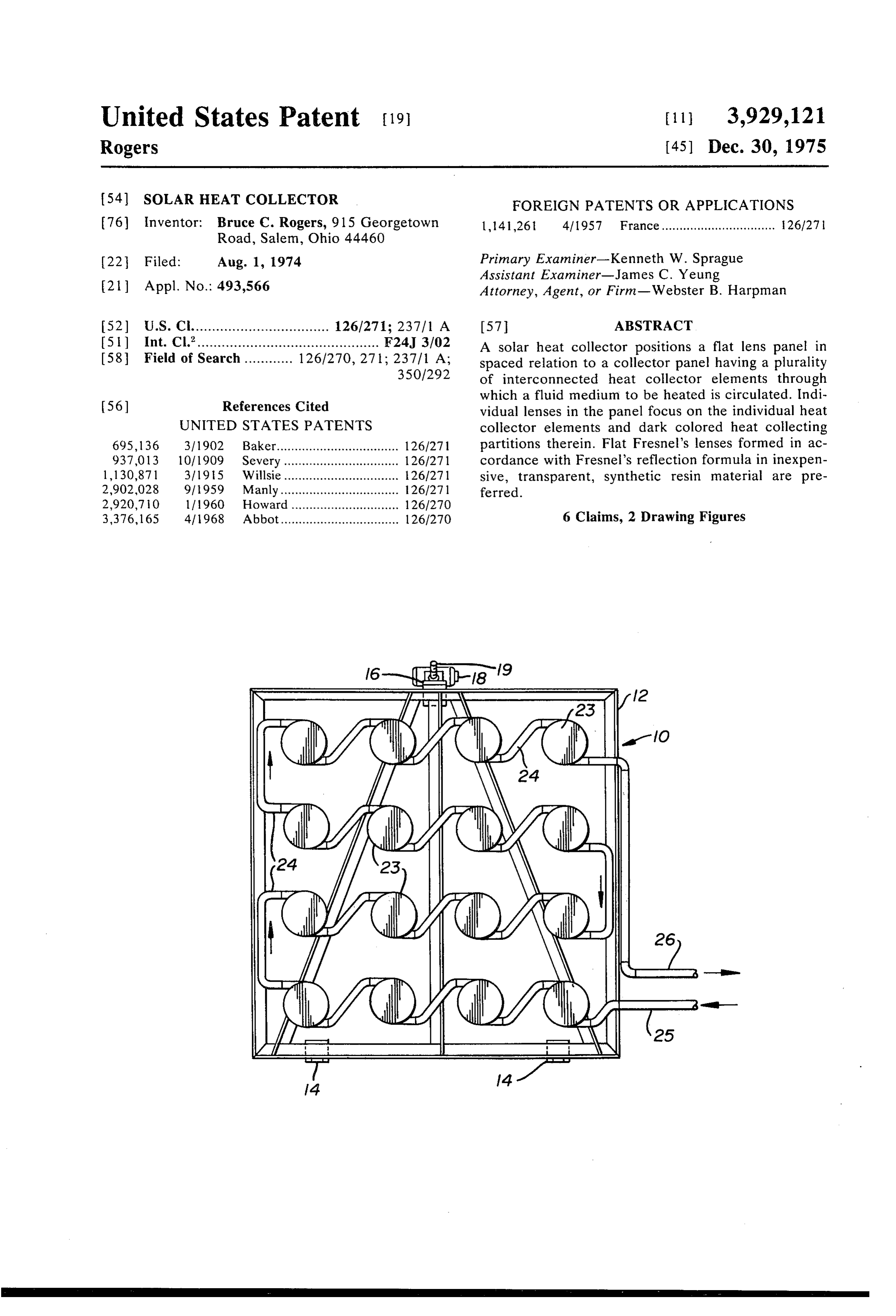
United States Patent 19 11, 3,929,121 Rogers (45) Dec. 30, 1975 54 SOLAR HEAT COLLECTOR FOREIGN PATENTS OR APPLICATIONS 76) Inventor: Bruce C. Rogers, 915 Georgetown 1,141,26t 4/1957 France................................ 26/27 Road, Salem, Ohio 44460 (22 Filed: Aug. 1, 1974 Primary Examiner-Kenneth W. Sprague Assistant Examiner-James C. Yeung 21 Appl. No.: 493,566 Attorney, Agent, or Firm-Webster B. Harpman (52) U.S. Cl.................................. 126/271; 237/1 A 57 ABSTRACT 5 Int, Cl.............................................. F24J 3702 A solar heat collector positions a flat lens panel in 58 Field of Search ............ 126/270,271; 237. A spaced relation to a collector panel having a plurality 35O1292 of interconnected heat collector elements through which a fluid medium to be heated is circulated. Indi (56) References Cited vidual lenses in the panel focus on the individual heat UNITED STATES PATENTS collector elements and dark colored heat collecting 695, l 36 31 l902 Baker.................................. 1261271 partitions therein. Flat Fresnel's lenses formed in ac 937,013 10/1909 Severy ................................ 126/271 cordance with Fresnel's reflection formula in inexpen 1,130,871 31195 Willsie................................ 1261271 sive, transparent, synthetic resin material are pre 2,902,028 9/1959 Manly................................. 126/271 ferred.
2,920,70 lf 1960. Howard .............................. 1261270 3,376, 165 411968 Abbot................................. 126/270 6 Claims, 2 Drawing Figures
Page 2
Drawing sheet — no readable text.
Page 3
Drawing sheet — no readable text.
Page 4
which carries an electric motor 18 and a gear reduction
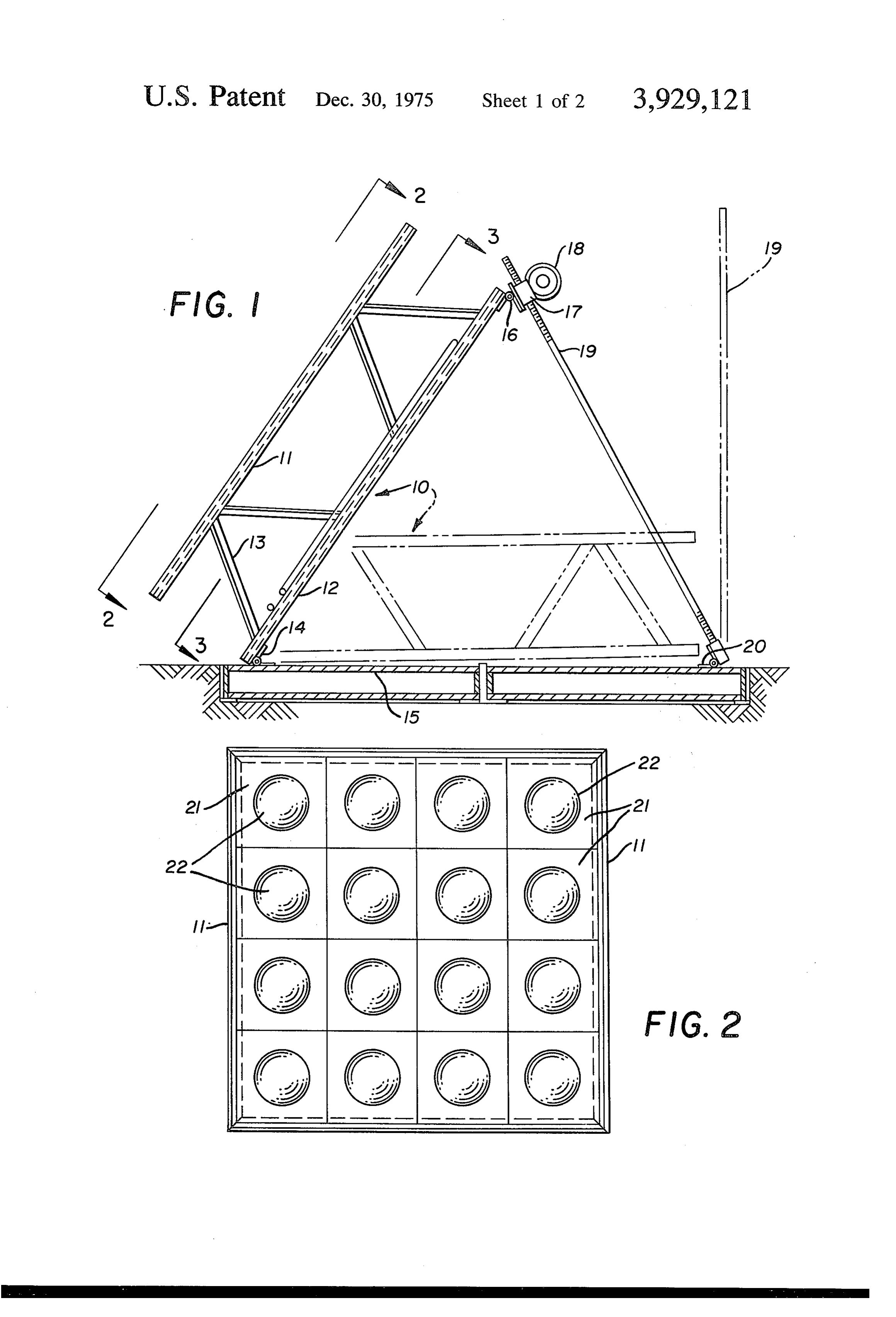
SOLAR HEAT COLLECTOR unit driven thereby and engaged on a threaded shaft 19 BACKGROUND OF THE INVENTION which in turn is hinged at its lower end by a third hinge 20 also secured to the rotatable base 15.
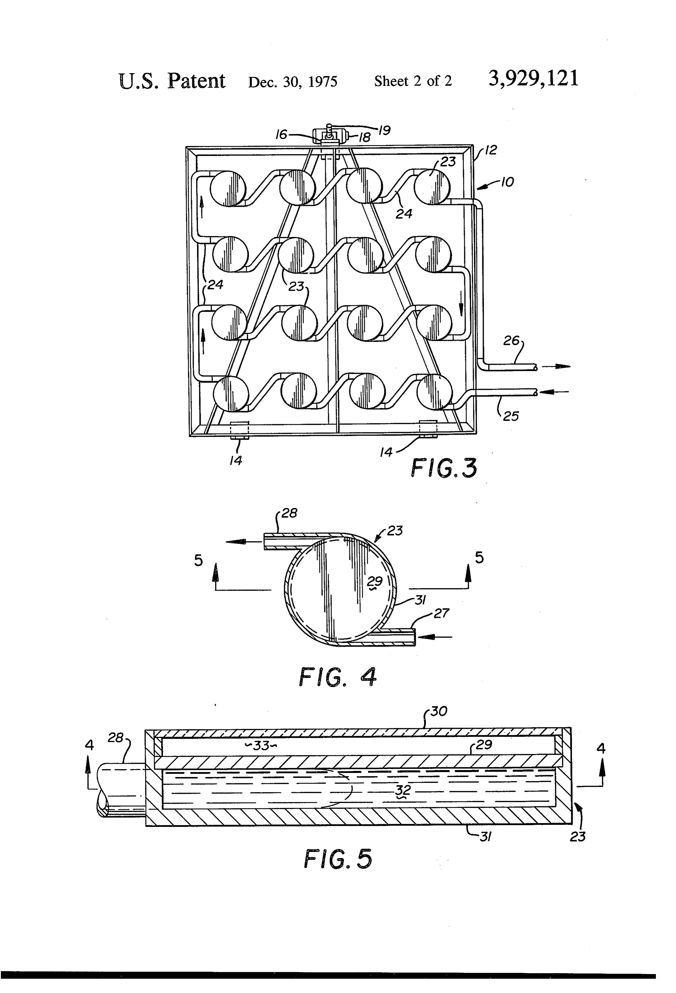
1. Field of the Invention Broken lines in FIG. 1 of the drawings indicates the This invention relates to solar heat collectors of the positioning of the solar heat collector in an alternate type normally employed to heat a fluid medium by position to that shown in solid lines and it will occur to sunlight. those skilled in the art that the solar heat collector thus 2. Description of the Prior Art supported can follow the sun. Prior structures of this type usually employ an insu 10 By referring now to FIG. 2 of the drawings, a plan lated container having a transparent wall and fluid view of the lens supporting portion 11 of the frame 10 conducting means therein. Such as for example in U.S. may be seen to position a plurality of flat sections 21 of Pat. Nos. 2,202,756 and 2,705,948. Variations of this transparent plastic material in which Fresnel lens con arrangement are found in U.S. Pat. Nos. 1,801,710 and figurations 22 have been formed such as by molding the 1,855,815. Lenses incorporated in the insulated enclo 15 same integrally with the plastic material and as will be sure and generally in closely spaced relation to the understood by those skilled in the art. means for the circulating fluid medium are seen in U.S. By referring now to FIG. 3 of the drawings, a plan Pat. Nos. 1,093,498, 1,673,429 and 2,902,028. view of the heat collector elements supporting portion A similar device incorporating reflectors but elimi 12 of the frame 10 may be seen supporting a plurality nating the lenses may be seen in U.S. Pat. No. of heat collector elements 23 interconnected in series 2,467,885 and a device having both lenses and reflec with suitable fluid carrying tubing 24 so that fluid me tors focused on a single fluid medium carrier is dis dium to be heated enters as shown by the arrows in closed in U.S. Pat. No. 1,683,266. FIG. 3 of the drawings at 25 and flows successively This invention provides a plurality of lenses spaced 25 through the plurality of heat collecting elements 23 and with respect to a plurality of heat collector elements a leaves at point 26. Each of the heat collecting elements distance approximating the focal depth of the lenses 23 is preferably a thin, flat, two-part glass bulb having employed so that the heat collecting elements and the oppositely disposed and tangentially arranged inlet and dark colored partitions therein receive greatly magni outlet portions 27 and 28 with a transverse dark col fied sunlight at relatively high temperatures. ored partition 29 positioned in spaced relation with 30 respect to the front and back portions 30 and 31 of the
SUMMARY OF THE INVENTION
heat collecting element 23.
A solar heat collector includes a frame having a lens The dark colored heat collecting partition 29 forms panel and a heat collector element panel in spaced two chambers in each of the heat collecting elements relation and means for circulating fluid to be heated 23. The larger of these chambers is indicated by the through the heat collecting elements together with 35 numeral 32 and communicates with the tangentially means for rotating the solar heat collector on its verti positioned inlet and outlet 27 and 28 respectively, the cal axis and means for tilting the solar heat collector arrangement being such that fluid entering the heat from a near horizontal position to an angled position of collecting element is confined to the larger chamber 32 approximately 45° from horizontal. Flat, inexpensive, 40 where it wipes the one surface of the dark colored heat plastic, Fresnel lenses focus sunlight on the individual collecting partition 29. The partition 29 is sealed with heat collectors to attain an efficient rapid heating of the respect to the back portion 31 of the heat collecting fluid being circulated through the individual heat col element 32 and the front portion 30 of the heat collect lector elements which are preferably interconnected in ing element 23 is spaced with respect to the partition a series relation. 29 and sealed to the annular flange forming the periph 45 eral edge of the back portion 31 so that a dead-air
DESCRIPTION OF THE DRAWINGS space or a partial vacuum chamber 33 results to insure FIG. 1 is a side view of the solar heat collector with against loss of heat directed against the partition 29 by parts broken away and parts in broken lines indicating the lenses 22 as hereinbefore described. alternate positions, Those skilled in the art will observe that when the FIG. 2 is a plan view on line 2-2 of FIG. 1, 50 plurality of lenses 22 are spaced desirably with respect FIG. 3 is a plan view on line 3-3 of FIG. 1, to the heat collector elements 23 the focul points of the FIG. 4 is an enlarged transverse section of one of the lenses 22 are on the partitions 29 so that the same are heat collector elements seen in FIG. 3, and heated rapidly to a very high temperature by the magni FIG. 5 is an enlarged section on line 5-5 of FIG. 4. fied sunlight.
55 It will occur to those skilled in the art that it may be
DESCRIPTION OF THE PREFERRED
EMBODIMENT desirable to provide insulation on the back side of each of the heat collecting elements 23 to insure against heat
In the form of the invention chosen for illustration loss therefrom and that the communicating means 24 the Solar heat collector comprises a frame 10 as seen in 60 interconnecting the elements 23 may also be suitably FIG. 1 of the drawings, having a lens supporting portion insulated. Flexible insulated hoses may be incorporated 11 and a heat collector element supporting portion 12 in the fluid supplying and delivering means so that the spaced by a plurality of frame members 13. In plan movement of the solar heat collector will not interfere view as seen in FIGS. 2 and 3 of the drawings which are with the efficient circulation of the fluid through the taken on lines 2-2 and 3-3 of FIG. 1 respectively, the device.
frame is substantially square. It is hinged at one of its 65 The above described solar heat collector structure ends by hinges 14 to a rotatable base 15 which is rotat provides relatively easy and fast adjustments so as to able on its vertical axis. The opposite side of the frame enable it to follow the sun and operate at maximum 10 is secured by a secondary hinge 16 to a bracket 17 efficiency and it concentrates the magnified sunlight
Page 5
from each of the plurality of lenses 22 in the individual lens so that said magnified light is at its maximum mag heat collecting elements 23 in a highly effective man nification on said heat collecting element. ner. The construction of each of the heat collecting 2. The improvement in a solar heat collector set forth elements 23 to incorporate the tangentially positioned in claim 1 and wherein a dark colored heat collecting inlet and outlet openings prevents direct flow through member is disposed transversely in said heat collecting of the fluid being heated as the same spins in the trans element in spaced relation to said flat top and bottom versely flat chamber 32 of each of the elements to walls and wherein said lens focuses light at its maxi provide a suitable time factor for the absorption of heat mum magnification on said dark colored heat collect from the dark colored heat collecting partition 29 O ing member.
therein. 3. The improvement in a solar heat collector set forth Although but one embodiment of the present inven in claim 1 and wherein said tangentially arranged inlet tion has been illustrated and described, it will be appar and outlet openings are circumferentially spaced in ent to those skilled in the art that various changes and said peripheral wall.
modifications may be made therein without departing 15 4. The improvement in a solar heat collector set forth from the spirit of the invention. in claim 2 wherein each of said heat collecting elements Having thus described my invention what I claim is: is a hollow device with spaced top and bottom walls at 1. In a solar heat collector having a plurality of heat least one of which is transparent and at least one of collecting elements, each of which comprises a round which has an integral peripheral flange joining the hollow transparent member having spaced flat top and 20 other, said heat collecting elements arranged in spaced bottom walls with a peripheral wall joining their annu relation and tubing interconnecting said heat collecting lar edges, inlet and outlet openings in said peripheral elements in series relation and forming part of said wall, at least one of said inlet and outlet openings tan means for circulating said fluid.
gentially arranged with respect to said peripheral wall, 5. The improvement in a solar heat collector set forth means for circulating fluid to be heated successively 25 in claim 1 and wherein each of said heat collecting through said heat collecting elements and a plurality of elements is substantially smaller in size than each of light magnifying lenses each of which is arranged in said lens focused thereon.
spaced parallel relation to one of said heat collecting 6. The solar heat collector of claim 1 and wherein elements and spaced with respect thereto a distance said lens are Fresnelcklensck incka flat,
transparent
material.
equal to the focus depth of light passing through said 30
Provenance
- Collection
- Cited prior art
- Original PDF
- patentimages.storage.googleapis.com →
- Filed
- 1974-08-01
- Pages
- 5
- Method
- pdftotext (the PDF's own text layer) + pdftoppm 300dpi page scans
- Source
- Google Patents bibliographic record
- Granted
- 1975-12-30
- Inventors
- Bruce C Rogers
- Transcribed from
- patentimages.storage.googleapis.com →