patent · US4243018
Solar energy concentrator
6 January 1981
Page 1 — bibliographic record
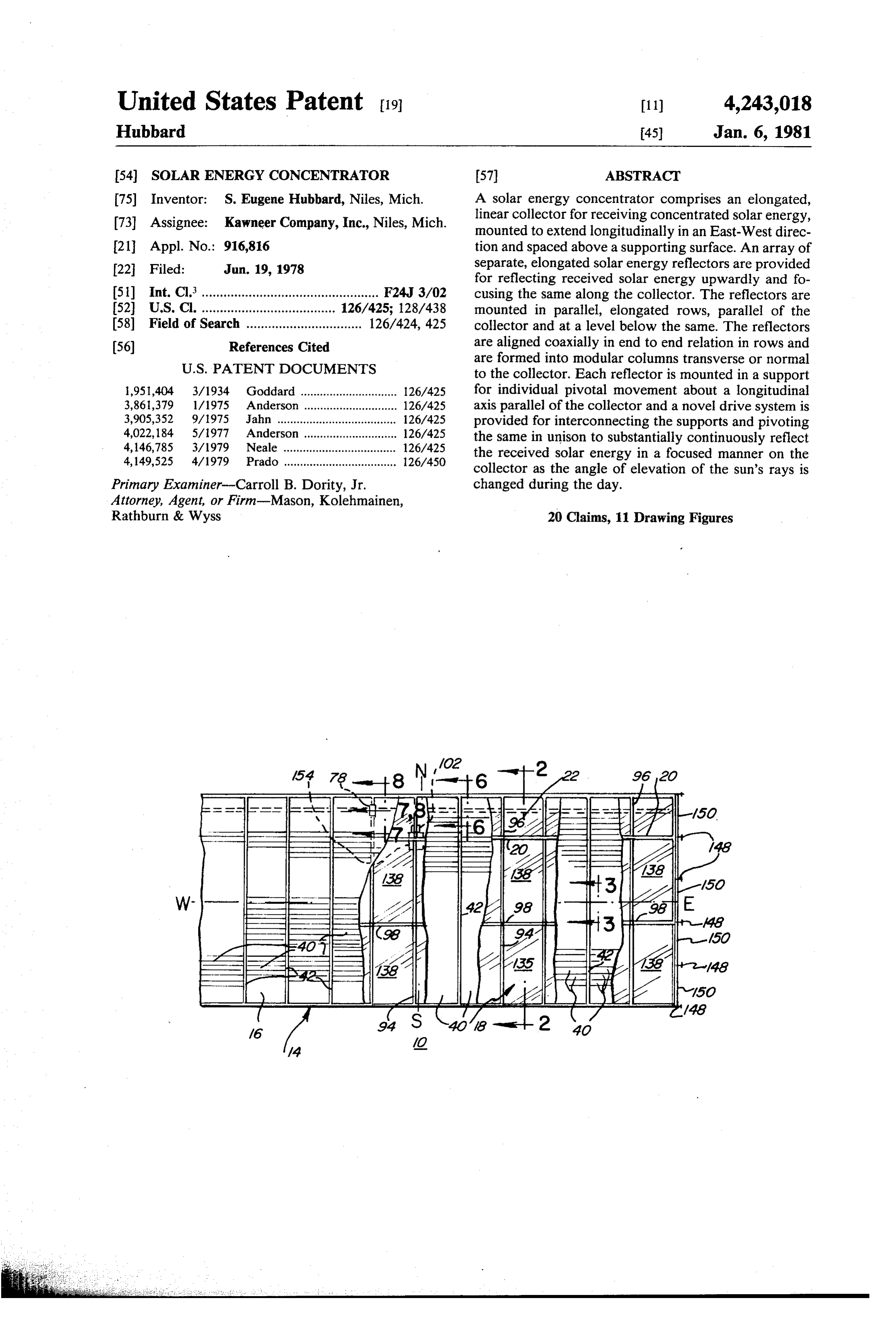
United States Patent (19) 11) 4,243,018 Hubbard 45) Jan. 6, 1981 54). SOLAR ENERGY CONCENTRATOR 57 ABSTRACT 75 Inventor: S. Eugene Hubbard, Niles, Mich. A solar energy concentrator comprises an elongated, 73 Assignee: Kawneer Company, Inc., Niles, Mich. linear collector for receiving concentrated solar energy, mounted to extend longitudinally in an East-West direc 21 Appl. No.: 916,816 tion and spaced above a supporting surface. An array of 22 Filed: Jun. 19, 1978 separate, elongated solar energy reflectors are provided for reflecting received solar energy upwardly and fo 51) Int. Cl.................................................. F24J 3/02 Cusing the same along the collector. The reflectors are 52 U.S. C. ............. 126/425; 128/438 mounted in parallel, elongated rows, parallel of the 58) Field of Search ................................ 126/424, 425 collector and at a level below the same. The reflectors (56) References Cited are aligned coaxially in end to end relation in rows and are formed into modular columns transverse or normal
1,951,404 3/1934 Goddard .............................. 126/425 for individual pivotal movement about a longitudinal 3,861,379 1/1975 Anderson ... ... 126/425 axis parallel of the collector and a novel drive system is 3,905,352 9/1975 Jahn .......... ... 126/425 provided for interconnecting the supports and pivoting 4,022, 184 5/977 Anderson .. ... 126/425 the same in unison to substantially continuously reflect 4,146,785 3/1979 Neale .... ... 126/425 the received solar energy in a focused manner on the 4,149,525 4/1979 Prado ................................... 126/450 collector as the angle of elevation of the sun's rays is
Primary Examiner-Carroll B. Dority, Jr. changed during the day.
Attorney, Agent, or Firm-Mason, Kolehmainen,
Rathburn & Wyss 20 Claims, 11 Drawing Figures
Page 2
Drawing sheet — no readable text.
Page 3
Drawing sheet — no readable text.
Page 4
Drawing sheet — no readable text.
Page 5
Drawing sheet — no readable text.
Page 6
Drawing sheet — no readable text.
Page 7
Drawing sheet — no readable text.
Page 8
moving the array of individually pivotal reflectors in
SOLAR ENERGY CONCENTRATOR unison to efficiently concentrate the received solar en ergy in the collector.
BACKGROUND OF THE INVENTION Still another object of the present invention is to 1. Field of the Invention provide a new and improved solar energy concentrator The present invention relates to a new and improved having novel supports permitting individual adjustment solar energy concentrator for focusing and concentrat of each of the reflectors in an array thereof to provide ing received solar energy onto a fixed linear collector. for a maximum efficiency of concentration of the en More particularly, the solar energy concentrator of ergy on a fixed linear collector.
the present invention includes a tracking system O Yet another object of the present invention is to pro wherein a plurality of separate pivotally supported re vide a new and improved solar energy concentrator of flectors are provided in an array and are moved as the character described which provides a modular sys required to substantially continuously reflect and focus tem or reflectors in an array of rows and columns the solar energy received upwardly toward a fixed 5 readily adapted to be driven to provide a substantially linear collector. continuous concentration of the received solar energy 2. Description of the Prior Art focused toward an elongated linear collector as the Many different types of concentrators have been angle provided for directing solar energy as received toward duringoftheelevation day.
of the received solar energy changes a collector positioned at a focal point or extending Yet another object of the present invention is to pro along a focal line. Some of these concentrators have 20 vide a new and improved solar energy concentrator of been built and tested but, have run into a wide variety of problems making them uneconomical to build and/or the character described including means for sensing the operate in reference to the amount of solar energy actu level of solar energy after the rays are focused toward a ally collected thereby. One thermostatically controlled 25 collector.
non-tracking type solar energy concentrator is shown in More particularly, it is another object to provide a U.S. Pat. No. 3,915,148 and this concentrator uses a lens new and improved solar energy concentrator of the system for focusing the sun's ray in a line image extend character described includis means for sensing the ing in an East-West direction. This focused energy is level of focused solar energy adjacent a fixed collector directed toward one or more collector channels posi 30 and operable for activating and deactivating a drive tioned to extend in an East-West direction and the en means for moving a plurality of reflectors in response to ergy is used for heating a fluid which is directed a selected level of energy.
through the channels as controlled by thermostatic More particularly, it is an object of the present inven valves. tion to provide a new and improved solar energy con The present invention provides a fixed, elongated, centrator including means for deactivating a drive sys
linear collector unit for receiving focused solar energy tem for moving from a plurality of pivotally supported individual re solar energy is below the reflectors whenever the focused flectors mounted in an array which are driven to move a selected minimum value. in unison by a drive system so that the reflected rays are vide Yet another object of the present invention is to pro substantially continuously focused on the collector as a new and improved solar energy concentrator of the angle of elevation of the sun's rays changes during the character described including drive means for sub the day from morning to night. stantially continuously maintaining a maximum value of Accordingly, it is an object of the present invention focused reflective energy adjacent a fixed linear collec to provide a new and improved solar energy concentra tor extending in an East-West direction longitudinally. to. Yet another object of the present invention is to pro It is another object of the present invention to pro 45 vide a new and improved solar energy concentrator of vide a new and improved solar energy concentrator the character described employing a novel drive means employing a fixed linear collector arranged to extend for moving a plurality of individual reflectors in a mod longitudinally in an East-West direction and spaced ular array thereof in a manner minimizing angular de above an array of separate, pivotally mounted solar flection errors in focusing the received solar energy energy reflectors which are driven to reflect the re 50 toward a fixed linear collector.
ceived solar energy and focus the same along the collec Yet another object of the present invention is to pro tor. vide a new and improved solar energy concentrator of Another object of the present invention is to provide the character described having novel means for acquir a new and improved solar energy concentrator of the ing and following the sun as a source of solar energy in character described having a new and unique drive 55 a manner maximizing the value of concentrated focused system for moving the reflectors in the array to substan energy on a fixed linear collector. tially continuously maintain a focus of energy on the Yet another object of the present invention is to pro collector as the angle of elevation of the received solar vide a new and improved solar energy concentrator energy changes during the day from sunrise to sunset. having a new and improved enclosure which minimizes Yet another object of the present invention is to pro operational maintenance and provides a maximum effi vide a new and improved solar energy concentrator ciency of energy collection.
having a novel and efficient enclosure system which Yet another object of the present invention is to pro prevents contamination of the reflective surfaces and maintains the concentrator in operation at relatively vide a new and improved solar energy concentrator of high or peak efficiencies. 65 the character described which is relatively low in initial Yet another object of the present invention is to pro cost and relatively low in periodic maintenance and vide a new and improved solar energy concentrator of operational costs in relation to the amount of solar en the character described having a novel drive system for ergy collected.
Page 9
BRIEF SUMMARY OF THE INVENTION enlarged detail construction of a light detector element in accordance with the invention.
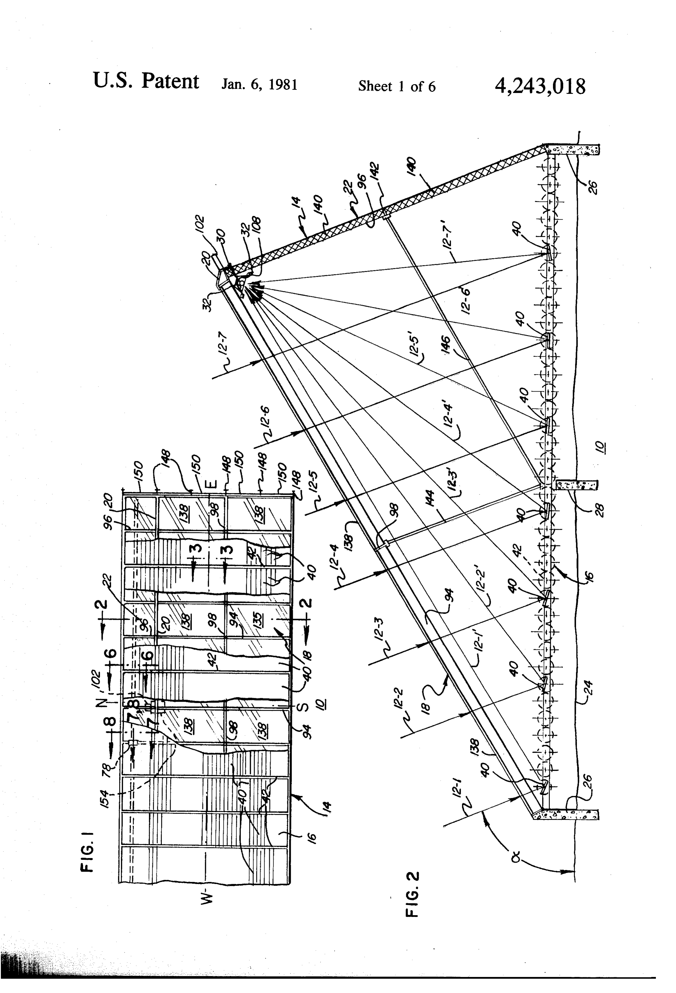
The foregoing and other objects and advantages of DESCRIPTION OF THE PREFERRED the present invention are accomplished in an illustrated EMBODEMENT embodiment comprising a new and improved solar en- 5 ergy concentrator having an elongated, fixed linear Referring now more particularly to the drawings, in collector for receiving concentrated solar energy FIGS. and 2 is illustrated a new and improved solar mounted to extend in an East-West direction spaced energy concentrator constructed in accordance with above a supporting surface. A modular array of rows the features of the present invention and referred to and columns of individual, elongated solar energy re 10 generally by the reference numeral 10. The concentra flectors such as mirrors are provided for reflecting the tor 10 is adapted to receive solar energy in the form of rays of solar energy received and focusing the same parallel rays 12-1, -2, -3, -4, -5, -6, -7, from the sun at an upwardly in concentrated fashion along the fixed col angle of elevation alpha relative to the horizontal which lector. The reflectors are mounted in parallel, elongated changes with the seasons of the year and is dependent rows, parallel to the collector and at a level spaced 15 upon the geographical location of the concentrator. below the collector in end to end relation. An individual During each day, as the sun moves from East to West, pivotally mounted support is provided for each reflec the angle of elevation alpha changes by a few degrees, tor in the array to permit pivotal movement thereof but for all practical purposes, however, during any about a longitudinal axis to accurately focus the energy given day, the angle of elevation (from a few hours received toward the collector. Novel drive means is 20 before to a few hours after the noon hour or meridian) provided for interconnecting the reflector supports of can be thought of as being relatively constant and the each column in the array for pivotally moving the re movement of the sun is approximated to be in a place flectors in unison to substantially continuously reflect sloped at the angle alpha, which is extended in an East the received rays of solar energy toward a linear focus West direction and intersects the surface of the earth in along the collector as the angle of elevation of the re 25 an East-West line.
ceived solar energy changes during the day from Sun The concentrator 10 is arranged with a longitudinal rise to sunset. axis thereof represented by the center line marked W-E BRIEF DESCRIPTION OF THE DRAWINGS and lying in an East-West direction so that as the sun rises in the morning and moves to sunset, it follows a
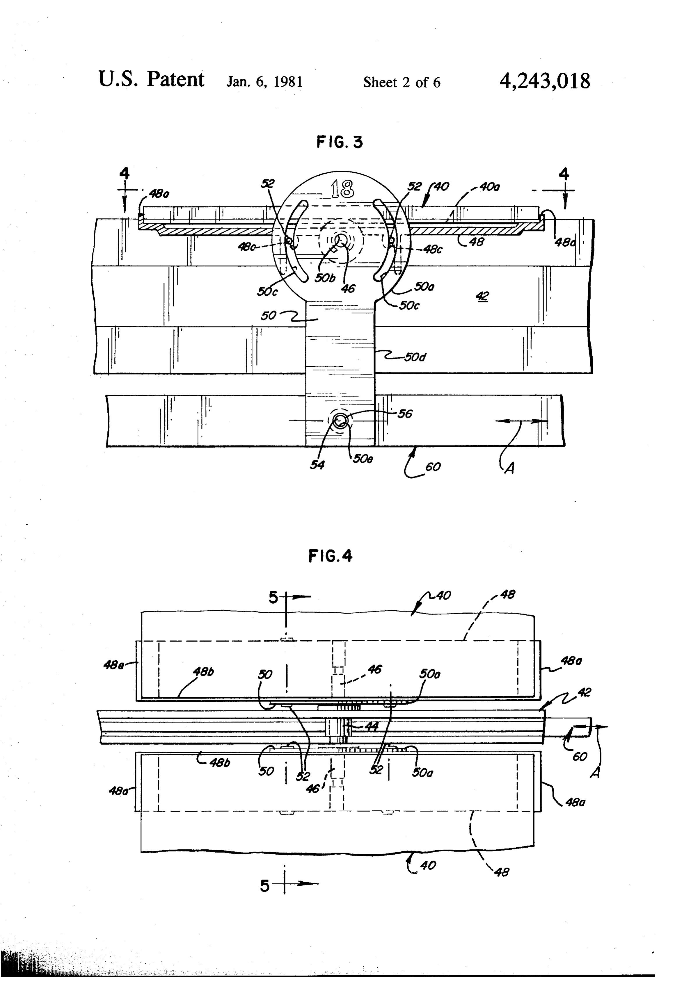
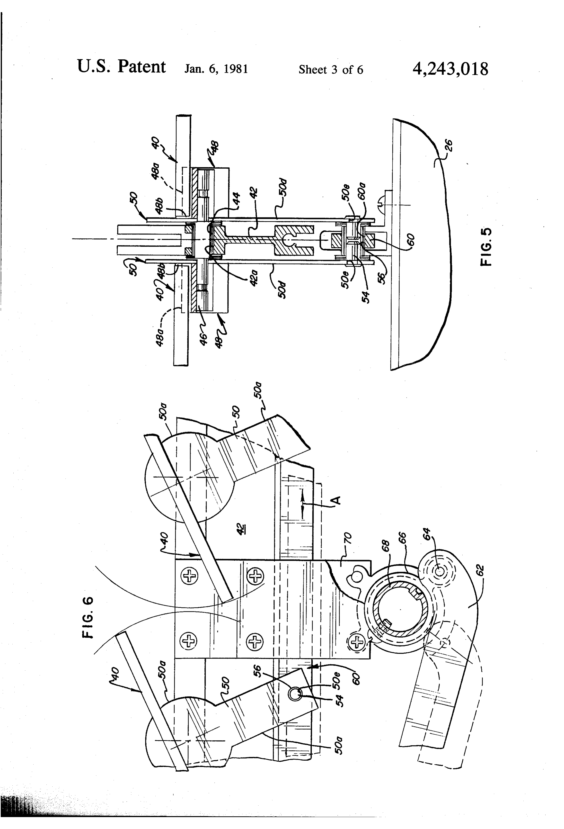
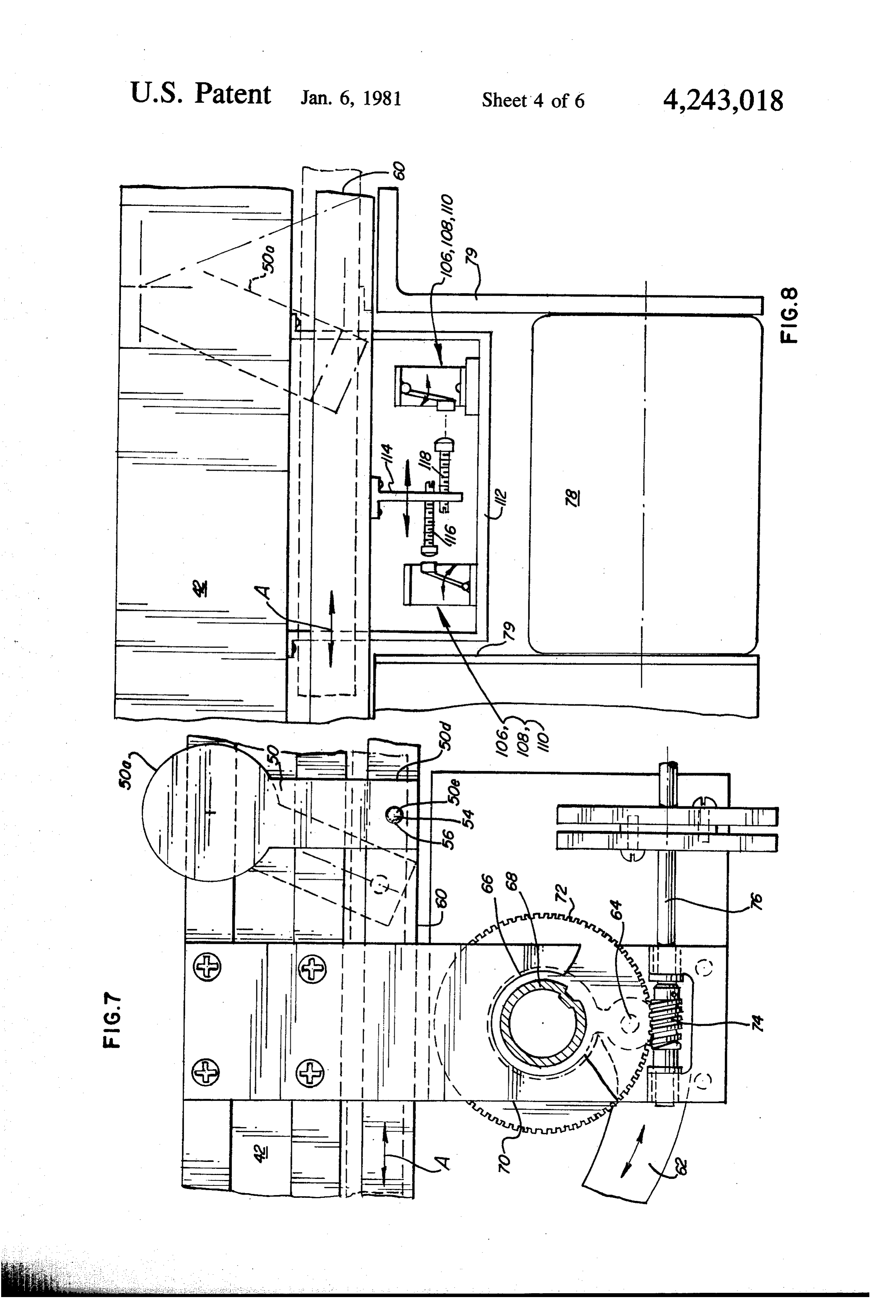
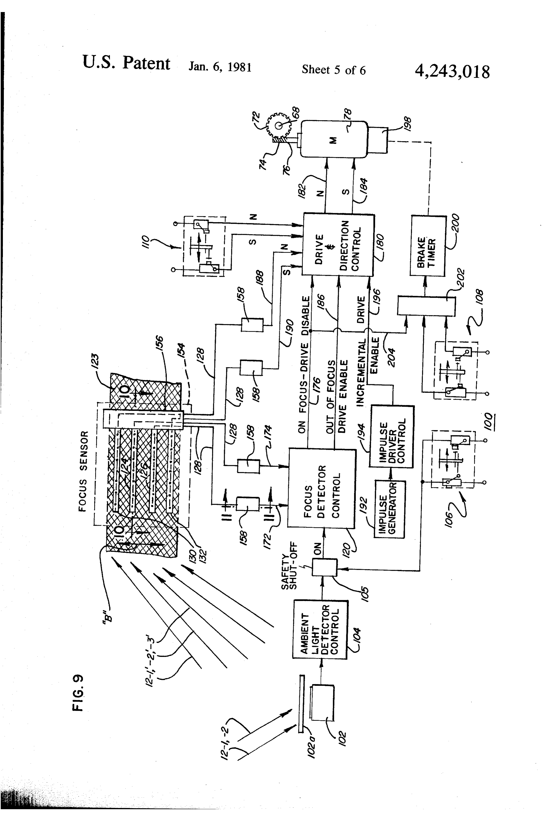
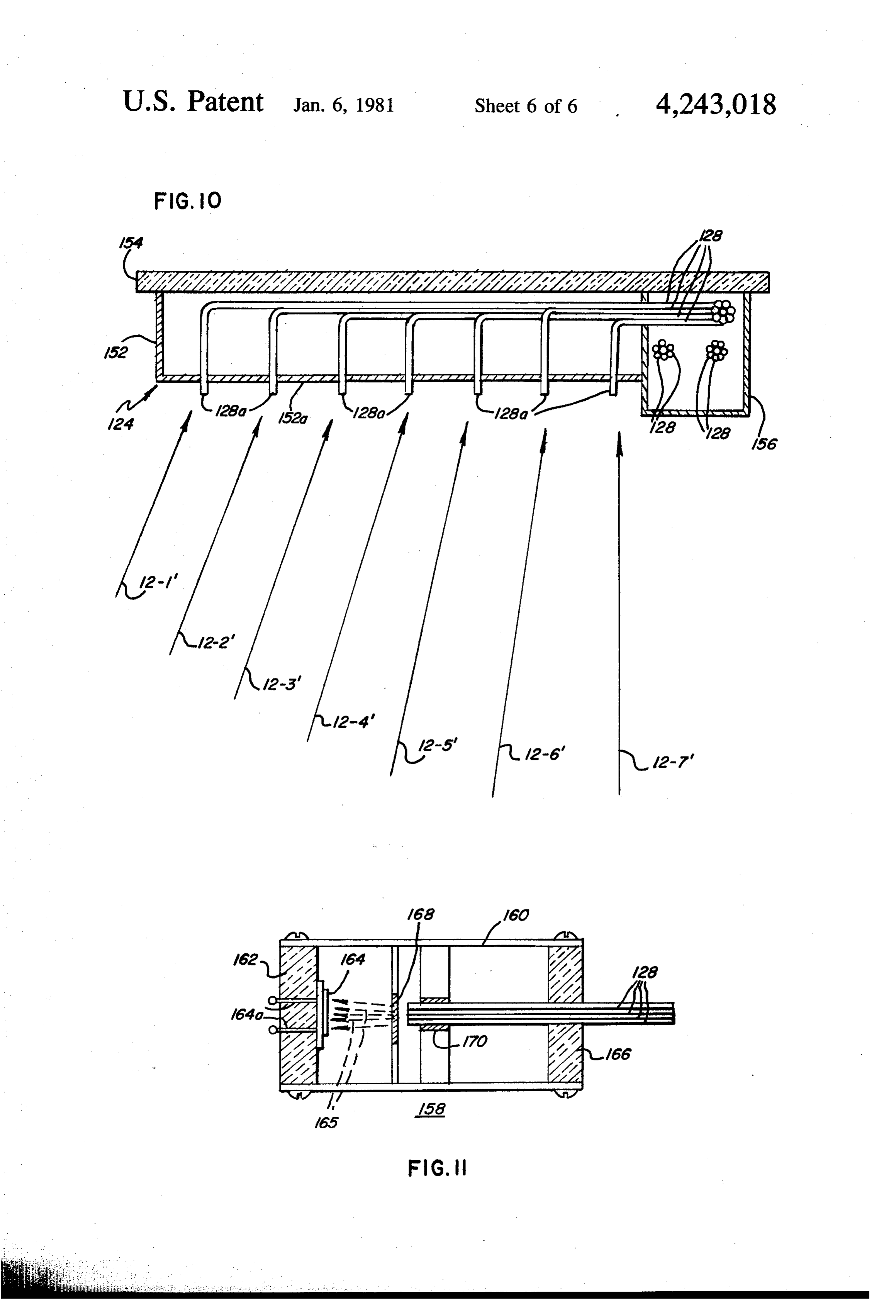
For a better understanding of the present invention, 30 linear path from the right hand end of the concentrator reference should be had to the following detailed de 10 as shown in FIG. , toward the left hand end. Be scription taken in conjunction with the drawings, in tween the hours of approximately 10 A.M. to 2 P.M., which: the Sun moves in a plane which changes in angle of FIG. 1 is a top plan view of a solar energy concentra elevation alpha by a relatively few degrees for all prac tor constructed in accordance with the features of the 35 tical purposes.
present invention with portions cut away showing the The concentrator 10 includes a housing or enclosure interior details of an array of reflectors thereof; 14 having a rectangular base or floor structure 16, a roof FIG. 2 is a vertical, transverse, cross-section of the structure or wall 18 sloping upwardly from a Southerly concentrator taken substantially along lines 2-2 of longitudinal edge of the floor structure toward a ridge FIG. 1; 40 or apex 20 which is interconnected or joined with the FIG. 3 is a greatly enlarged, fragmentary, vertical, upper edge of a back wall 22 sloping upwardly at a cross-sectional view taken substantially along lines 3-3 somewhat steeper angle from the Northerly longitudi of FIG. 1; nal edge of the floor structure. As illustrated in FIG. 2, FIG. 4 is a fragmentary, greatly enlarged, horizontal, the enclosure or housing 14 may be supported above the cross-sectional view taken substantially along lines 4-4 45 earth's surface which is represented by the numeral 24 of FIG. 3; or other structural surface on a suitable foundation wall FIG. 5 is a greatly enlarged, fragmentary, transverse, 26 of concrete or other appropriate material formed to vertical, cross-sectional view taken substantially along enclose the periphery of the floor structure. A number lines 5-5 of FIG. 4; of intermediate posts or walls 28 may be utilized as FIG. 6 is a greatly enlarged, vertical, transverse, required to provide adequate physical support for the cross-sectional view taken substantially along lines 6-6 floor and roof structures at points or locations within of FIG. ; the interior of the housing or enclosure 14. FIG. 7 is a greatly enlarged, fragmental, vertical, In accordance with the present invention, the hous cross-sectional view taken substantially along lines 7-7 ing or enclosure 14 provides support for an elongated, of FIG. 1; 55 linear, energy collecting element 30 supported below FIG. 8 is a greatly enlarged, vertical, transverse, the ridge 20 of the enclosure and extended in an East cross-sectional view taken substantially along lines 8-8 West direction spaced above the level of the floor struc of FIG. 1; ture 16. The linear collector 30 may comprise a hollow, FIG. 9 is a schematic diagram illustrating an electri tubular conduit for containing a flow of heat conductive cal circuit of the drive system used with the array of 60 gas or fluid heat for absorbing the heat of concentrated reflectors of the concentrator for controlling the move or focused sun rays. In the alternative, the collector ment thereof in accordance with the present invention; may comprise photo-coltaic cells which are adapted to FIG. 10 is a North-South vertical, cross-sectional convert the reflected solar energy into electrical energy view taken substantially along lines 10-10 of FIG. 9 is useful quantities or may include fibre-optic materials showing in enlarged detail the construction of a focus 65 for receiving the reflected sunlight and directing the sensor in accordance with the invention; and same to another location for conversion into electrical FIG. 11 is a longitudinal cross-sectional view taken energy. This latter alternative is advantageous in that substantially along lines 11-11 of FIG. 9 showing in quartz fibres can withstand the high temperatures pro
Page 10
duced. There may also be provided a parabolic cross center axis by a pair of trays or pans 48 which are car sectionally shaped reflector 32 for further focusing the ried on the outer ends of stub axles 46. The stub axles reflected solar energy toward the linear collector ele are rotatable in bearing sleeves 44 mounted in the open ment which is positioned at the focal point thereof of ings 42a of the rails 42.
the parabolic profile. 5 In accordance with the present invention, pairs of In accordance with the present invention, the linear mirror support trays or pans 48 disposed on opposite collector 30 is adapted to receive concentrated or fo sides of each joist or rail 42 in the floor structure 16, are cused solar rays 12-1', -2, -3', 4', -5,-6, -7", which have provided with keyhole shaped actuating arms 50 used been reflected upwardly from a plurality of elongated, for pivoting the mirrors in order to maintain the focus rectangular reflectors 40 aligned longitudinally in end 10 of the upwardly reflected rays concentrated on the to end relation in East-West rows and transversely ex linear collector 30 as the sun angle alpha changes. Each tending North-South oriented columns as best shown in of the actuating arms 50 includes a circular, enlarged FIGS. 1 and 2. Each reflector is supported for pivotal upper end portion 50a having a central aperture 50b movement relative to a longitudinal, East-West, cen aligned with a supporting stub axle 46 as best shown in trally disposed pivot axis to that the incoming rays of 15 FIGS. 3 and 4. In addition, the enlarged upper end the sun which strike a reflective, mirrored surface 40a portion 50a of each arm is formed with a pair of arcu on the bottom face thereof are reflected upwardly at a ately shaped slots 50c disposed on opposite sides and in proper angle and are focused or concentrated on the concentric relation with the central aperture 50b. These linear collector 30. Referring momentarily to FIG. 2, it arcuate slots are aligned with a pair of extruded splines will be seen that an incoming sun ray 12-1 strikes a row 20 48c formed on the underside of the mirror support pans of reflective mirrors that are closely adjacent the South 48 (FIG. 3) in order to receive headed fasteners 52. erly edge of the concentrator housing and these mirrors These fasteners include shanks which extend through are tilted at an angle so that a reflective ray 12-1' is the arcuate slots and into the extruded splines 48c of the directly upwardly to strike the elongated collector 30. mirror supporting pans to hold the arm and support pan Similarly, the incoming parallel sun rays 12-2, -3, etc. 25 in a selected angular relation. strike different rows of reflectors, each of which is set at Each keyhole shaped arm 50 also includes a down a particular angle so that the reflected rays 12-2, -3', wardly depending leg portion 50d having an aperture respectively, will be concentrated and focused on the 50a or 50e adjacent the lower end for accommodating a elongated collector 30 adjacent the ridge 20 of the en knuckle pin 54 (FIG. 5) which is mounted in a sleeve closure. 30 bearing 56 seated in an aperture 60a provided in an The reflectors 40 may be high quality, glass mirrors elongated column actuator rod 60 having a plurality of or may be highly polished metal elements so that a such apertures spaced at longitudinal intervals at the maximum efficiency of reflected energy is achieved. same spacing distance between the parallel longitudinal Each reflector in each individual row of reflectors is center axes of the mirror reflectors 40 in adjacent rows selectively adjusted with a tilt angle so that the parallel 35 of the array.
incoming rays striking all of the mirrors will be concen Referring now to FIGS. 3, 4, 5, 6, 7 and 8, each col trated or focused upwardly towards the linear collector umn actuator rod 60 is provided to control the move 3. ment of a pair of North-South columns of reflectors 40 As illustrated in F.G. 2, each row of reflective mir disposed on opposite sides thereof. A single column rors 40 will have a slightly different angle of tilt or actuator rod is interconnected with a pair of arms 50 on elevation with respect to adjacent rows and this is nec opposite sides of the supporting rail 42 for each row of essary so that the incoming parallel sun rays will all be reflectors in the array and these arms in turn, are adjust focused to converge upwardly or a focus on the linear ably interconnected to pivot the mirror support pans or collector 30. As indicated in the plan view of FIG. 1, trays 48 associated therewith. The column actuator rods the reflective mirrors are arranged in a rectangular 45 are movable back and forth longitudinally as indicated array including columns extending on a North to South by the arrows 'A' causing the actuator arms 50 to pivot axis and the mirrors are set in longitudinally aligned and thereby move the reflective mirror 40 of each col rows extending in an East-West direction. umn to pivot in unison and continuously focus and Each reflector is supported for individual pivotal concentrate the reflected solar energy rays on the linear movement adjacent its opposite ends from a pair of SO collector 30.
spaced apart parallel rails 42 of the floor structure 16 A column actuator rod is interconnected to all of the and these rails extend in a North-South direction form depending arm portions 50d of the adjacent reflector ing transverse structural emembers or joists of the floor mirrors 40 on opposite sides of the rail 42, and each structure. The rails 42 are shown in transverse cross individual mirror support pan 48 is connected at the section in FIG. 5, and are formed with a plurality of 55 time of manufacture at the desired angle to accurately openings 42a in the web which are spaced at suitable focus its reflective sun rays on the collector 30. intervals aligned with the central axes of the mirrors. In The arms are numbered as shown in FIG. 3 and the each opening, an annular sleeve bearing 44 is provided numbers refer to the row in the array. It will thus be to support a stub axle 46 extending laterally outwardly seen that each mirror 40 is driven to rotate by the rotat from opposite sides of the rail. Each stub axle carries a able support trays at opposite ends thereof. After the pair of mirror and support pans or trays 48 and the pans desired angular alignment between an arm and support are formed with lips 48a at opposite ends for containing tray is set (preferably on a jig at the factory, the fasten the longitudinally extending, opposite edges of the mir ers 52 are inserted or tightened with their heads against rors that are carried thereon. The pans also include end the edges of the arcuate slots 50c in the upper portions walls 48b adapted to abut opposite ends of the reflective 65 50a of the arms to secure the correct relative angular mirrors. As best shown in FIGS. 3, 4 and 5, it will be position between the arm and the reflector support 48 seen that each mirror 40 is supported at opposite ends associated therewith. During operation, movement of for adjustable pivotal movement about a longitudinal the column actuator rods longitudinally in one direction
Page 11
or the other, will continuously focus reflected rays from other contaminating materials which will reduce the mirrors 40 in the array on the linear collector, and be reflective efficiency thereof. In this connection, the cause each mirror is supported at both ends and rotated concentrator housing 14 is provided with a plurality of by a pair of column actuator rods, backlash is eliminated upwardly sloping rafters 94 extending upwardly from or greatly reduced and an accurate focusing of the re the Southerly foundation wall of the enclosure to the flected sun's rays is achieved as the mirrors are driven apex or ridge 20. Preferably, the rafters are aligned to rotate during the day's operation. directly above the rails 42 of the floor structure 16 and A substantially continuous focus or convergence of are interconnected at the apex or ridge with upwardly the reflected rays 12-1, -2, -3' etc. is maintained on a sloping, back wall rafters or uprights 96 as shown in focal area around the linear collector 30 and its sur 10 FIG. 2. Intermediate the ends of the rafters there may rounding reflector 32 as shown in FIG. 2 in this manner. be provided longitudinally extending purlins 98 which The respective parallel column actuator rods 60 are provide support for horizontal edges of rectangular, driven to move in a linear fashion back and forth to glazing panels 138 used to keep out dust and other move the respective columns of mirrors 40 to follow the weather elements, yet permit the solar rays 12-1, -2, -3, sun and focus a linear image on the collector 30. For this 15 etc. to pass downwardly therethrough for reflection purpose, each actuator rod is pivotally interconnected from the rows of reflective mirrors 40 as previously with an arm 62 (FIGS. 6 and 7) having an opposite end described. The glazing panels may be readily cleaned pivotally connected by a pin 64 to a collar 66 mounted from outside of the enclosure from time to time to mini on a common drive shaft 68 extending longitudinally of mize energy losses while the inside area within the the array of reflectors in an East-West direction. The 20 structure is maintained substantially free of dust, dirt shaft 68 is supported on suitable bearing brackets 70. and other contaminating influences.
depending downwardly at appropriate intervals from The sloping back wall 22 of the concentrator housing the respective rails 42 in the floor structure 16 of the 14 is provided with a wall structure 140. The wall in concentrator enclosure. The drive shaft is of a relatively cluding backside panels are disposed between adjacent large diameter and low weight construction to minimize 25 backside rafters or uprights 96 and horizontal backside the amount of rotational deflection or backlash along its purlins 142 may be provided between adjacent rafters length. This helps to maintain accurately focused re for supporting the horizontal edges of the insulating flected energy from the reflectors of the array going panels. If required, as dependent upon the span or from column to column. length of the rafters 94 and the back wall uprights 96, The shaft is driven to rotate from a mid-point longitu 30 intermediate braces 144 and 146 may be provided and dinally thereof by means of a drive gear 72 which is these are supported at the lower ends from the interme keyed to the shaft and is mounted adjacent a mid-point diate foundation wall or posts 28.
on the shaft which extends outwardly thereof in oppo As viewed in FIG. 1, the concentrator enclosure is site directions along an East-West direction. The shaft is also provided with a triangular shaped end wall struc rotatable in both directions as required and the gear 72 35 ture having parallel vertical columns 148 projecting is driven by a worm 74 mounted on the outer end por upwardly from the foundation end walls 26 to the end tion of a drive shaft 76 on a reversible, electrically pow most rafters 94. A plurality of transparent glazing panels ered motor 78 operating through a high ratio reduction 150 are provided between the upright columns 148 in gear train. As illustrated in FIGS. 1 and 8, the motor order to permit the entry of low angle, East-West sun and the reduction gearing are mounted on supportive rays onto the array of mirrors 40 when the sun is begin brackets 79 depending downwardly from a middle rail ning to rise in early morning or finally beginning to set 42 in the floor structure 16. When the reversible drive in the late of the day. As the sun begins to rise, in the geat motor 78 is electrically energized to rotate in one East, its rays are at a relatively low angle of elevation direction, the single shaft 68 and the respective column with respect to an East-West latitude line and these rays actuator rods 60 linked therewith are activated to move 45 enter the enclosure 16 of the concentrator 10 through in a given direction and when the direction of rotation the Eastern end wall structure glazing panels 150. These of the motor is then reversed, the column actuator rods rays are deflected upwardly in a Westerly direction by 60 move in an opposite direction causing the respective the mirrors 40 towards the linear concentrator 30 and mirror reflectors 40 in the columns on either side because of the relatively low angle they may strike the thereof to pivot as previously described. In this manner 50 concentrator 30 only at a Westerly end portion thereof. a substantially continuous maintenance of the focus or As the sun rises in the sky during the middle portion concentration of reflected sun rays 12-1, -2, -3', etc. on of the day, the angle of elevation “alpha' as measured the linear collector 30 at the apex or ridge of the enclo relative to a North-South longitudinal line reaches a sure is achieved. maximum at the mid-day meridian and changes very In order to further reduce the possibility of inaccu 55 little in the period from about two hours before through rate focusing of the reflected rays, the number of col two hours after the meridian is reached. However, as umns of mirrors on each side of the central drive motor the angle "alpha' of the sun's rays begins to increase is limited so that any rotational deflection of the drive during the mid-morning and decrease in the mid or late shaft 68 which might occur because of friction or bind afternoon, the mirror tilting and drive control system as ing of the linkage is minimized. This of course, limits the 60 described in accordance with the present invention, East-West length of the array that a single drive motor maintains on a substantially continuously basis, a maxi can efficiently operate and if additional reflective areas mum concentration or focusing of the reflected rays on are needed, separate arrays may be provided, each hav the linear collector. During the middle portion of the ing its own drive system. day, most of the sun's rays are received through the roof In order to maintain a maximum efficiency in opera 65 glazing panels 138 rather than the end wall panels 150 at tion of the concentrator 10, the housing or enclosure 14 either end of the enclosure.
provides protection against outside weather elements so From the foregoing, it will be seen that the solar that reflective mirrors 40 do not collect dust, dirt or energy concentrator in accordance with the present
Page 12
invention provides an extremely efficient means of con elements. Referring to FIGS. 9, 10 and 11, these ele centrating and collecting solar energy for a variety of ments each comprise a plurality of elongated optical different purposes. Any number of arrays as described, light transmitting fibers 128 having light receiving ends may be provided in an even larger array. The amount of 128a pointed downwardly toward the mirrors 40 for solar energy collected is roughly proportional to the 5 picking up reflected light rays therefrom. The sensors rectangular area of the whole array of mirrors within an 124 and 126 are spaced in parallel between a pair of enclosure. Extremely long enclosures in the East-West outwardly spaced, parallel, "fine” focus sensors 130 and direction may be provided if desired, however, in order 132 and as indicated schematically in FIG. 9, the focus to minimize backlash on the shafts and drive elements of image 123 of the reflected light rays 12-1, -2, -3", etc. the drive system because of angular deflection of the 10 from the mirrors 40 is of a width larger than the spacing drive shafts and frictional problems, it is desirable to between the outer sensors so that when the image is provide a plurality of separate, drive motors 78 and properly centered with respect to the array of both the shafts spaced in parallel at appropriate intervals along rough and fine focus sensors, all of the sensor elements the length of an extremely long enclosure. This will are shadowed as illustrated. Should the image move out ensure that a maximum reflective concentration is main 15 of centered position in either direction as indicated by tained and continued operation. the arrow 'B', one of the outer "fine' focus sensors 130 In accordance with the present invention, a control or 132 will be uncovered and accordingly, the reflected circuit 100 as illustrated schematically in FIG. 9, is sunlight input to that sensor will be greatly reduced. provided for energizing the reversible drive motor 78 in Referring to FIG. 10, each of the four focus sensors both directions to pivot the mirrors 40 in a manner to 20 include an elongated, hollow tubular structure 152 hav maintain a substantially continuous focus or concentra ing a bottom wall 152a therein facing the mirrors and tion of the reflected sun rays 12-1, -2, -3', etc. on the provided with a plurality of longitudinally spaced apart linear collector 30 as the angle of elevation "alpha' of openings for accommodating the downwardly extend the incoming sun rays 12-1, -2, etc. changes during the ing lower end portions 128a of the respective optical day and day to day during the seasons. Referring partic 25 fibers 128. The sensor tubes 152 are mounted in spaced ularly to FIGS. 2 and 9, an ambient light photosensor parallel rows on a base plate 154 which is mounted 102 comprising a solar cell is mounted outside the hous above the central rail 42 of the floor structure as shown ing 14 to sense the level of the ambient light available. in FIG. 1 and spaced just below the elongated collector Preferably, the solar cell is provided with an infra-red element 30. Each of the sensor tubular elements or filter 102a so that it will be sensitive only to infra-red 30 housings 152 is interconnected at one end to a trans energy and can thus determine when the tracking sen verse tubular structure 156 which is adapted to carry a sors are able to follow the sun's image even on cloudy plurality of bundles of the optic fibers or light pipes days. - from each of the focus sensor elements as best shown in When the level of energy sensed is above an adjust FIG. 10. These bundles of optical fibers are passed able set point, the concentrator 10 is turned on and an 35 outwardly through the back wall 22 of the concentrator enabling input signal is directed into an ambient detec housing structure 14 and each is connected to a light tor switching module 104. If the level of energy sensed detector unit 158 having a hollow housing 160 and is below the set value that would render collection adapted to convert solar energy into an electrical out uneconomical, the switch module is not enabled and the put.
system remains in an off condition. The light detectors are shown in detail in FIG. 11 and As illustrated in FIG. 8, the concentrator is provid each includes an end plug 162 forming a base for a solar with three sets of limit switches 106, 108 and 110, re cell 164 having a pair of leads 164a extending externally spectively, carried on U-shaped brackets 112 which are thereof for interconnection with the electrical circuit of mounted adjacent the central rail 42 of the floor struc the control system. The solar cells 164 are designed to ture and the switch sets are selectively activated by 45 receive infra-red rays 165 passing through an infra-red elements 114, each of which carries a pair of adjustable filter 168 from the exposed ends of the bundle of optical switch actuators 116 and 118. The elements 114 are light fibers 128 which extend into the housing 160 from mounted on the central control column actuator 60 and the opposite end through an opening in a removable are movable along a North-South axis between the pairs opposite end plug 166. The optical fibers are centered of limit switches in each set as the mirrors 40 are piv 50 coaxially with respect to the filter 168 and the solar cell oted. 164 by means of an internal bracket 170 so that an elec An outer set of safety limit switches 106 provides a trical signal is generated by the solar cell in response to safety shut-off capability for the system, should the the solar energy of the infra-red range that is received. mirror control drive column 60 move too far North or Similarly, referring to FIG. 9, the ambient solar cell 102 South. When either switch of this pair is activated, a 55 may be provided with an infra-red filter 102a so that the safety shut off function 105 is provided and the output cell responds chiefly to infra-red energy received from signal from the ambient detector 104, if present, is in the sun.
terupted. The North-South spacing interval between The electrical signals generated in response to the the switches of the set 106 is greater than the spacing light sensed by the inner two sensor or "rough' focus between the other sets of switches 108 and 110 and this 60 elements 124 and 126 are directed to the focus detector outer pair of switches are only activated when the sys control 120 through a pair of input cables 172 and 174 tem has malfunctioned. (FIG. 9). In the event the image 123 of focused reflected An "ON" or enabling output signal from the ambient energy is in a position covering both of the sensor ele light detector control 104 provides an input signal to a ments 124 and 126, an input signal is sent to the focus focus detector switch 120. The focus detector provides 65 detector control 120 through both the input cables 172 an enabling signal via an output lead 176 whenever the and 174.
focus image 123 of the sun rays 12-1', -2", is not covering In this condition, an output signal is generated by the both sensors 124 and 126 of a pair of “rough" focus focus detector and is sent, via one output cable 176 to a
Page 13
drive and direction control 180 which provides drive signal output and cause the motor 78 to reverse the and direction signals via output cables 182 and 184 direction of mirror tilting.
labeled North and South, respectively, for energizing Similarly, when the North limit switch of the set 110 the motor 78 in the proper direction to pivot the mirrors is activated, the flip-flop is reactivated to reverse the and change the position of focused image 123 of the sun direction of drive of the motor 78. Once the inner two with respect to the sensors. The output cable 176 from “rough' focus sensors 124 and 126 are covered by the the focus detector control provides an "on-focus, drive image 123 the "On-Focus Drive Disable' signal is sent disable' signal to the drive and direction control and in to the control unit 180 via the cable 176 as described and response to this signal, the drive and direction control the drive and direction control unit is then operable to unit will then only permit incremental drive impules to 10 drive the motor with short, timed drive pulses via re be dispatched through the output leads 182 or 184 as spective input lines 182 and 184 to track the sun and will be described hereinafter. In the event, however, keep the image centered as the sun angle changes. that the focus image 123 covers only one and not the For this purpose, the circuit 100 includes a square other of the inner two "rough' focus sensors 124 and wave impulse generator 192 which provides a train of 126, an electrical signal will be provided to the focus pulses to an impulse driver control 194. The impulse
detector control 120 from only one of the input leads driver control is adjustable to select the number, fre 72 or 74. When this condition occurs, an "out-of quency and/or time duration of a train of pulses which focus drive enable' signal is provided via another out are directed into the drive and directional control 180 put lead 186 also connected to the drive and direction via an input line 196. Dependent upon the input signal control switch 180. With an enabling signal, activation to the drive and direction control from the North and
of the motor 78 in the appropriate direction is accom /or South input cables 188 and 190 and the input re plished to pivot the mirrors in the corresponding direc ceived from the reversing set of limit switches 110, the tion to bring the image 23 into centered position. It motor 78 is driven to rotate in short duration steps and will thus be seen that if the image 123 is covering both this maintains a centered position for the image 123 on of the “rough' focus sensor elements 126 and 124, the 25 the array drive and direction control 80 will generally be dis occurs evenof though focus sensor. This type of pulsed drive the focus detector control 120 is abled from providing normal speed drive outputs to the providing an "On-Focus motor 78. However, if only one and not the other of the input line 176 to the driveDrive Disable Signal” via the and direction control.
inner two sensors E26 and 124 is covered by the image, In accordance with the invention, the motor 78 is the "Out of Focus Drive Enable' signal will be pro provided with an electric brake 198 and the limit vided so that the drive direction control 180 then func tions to energize the motor 78 in the proper direction to tween the outerwhich switches 108, are positioned intermediate be set of switches 106 and the inner set bring the image into centered position with respect to the array of "rough' and “fine' focus detectors 124, 110, are provided for effecting braking action on the 126, 130 and 132, respectively. 35 motor through a brake timer 200. The momentum of the When the image 123 is accurately centered as indi mirror drive system generally carries the mechanism a cated in FIG. 9, it is wide enough to cover the outer slight distance beyond the limit set by the inside set of two "fine' focus sensors 130 and 132 and the bundles of reversing switches 110, and as this occurs, the North or light pipes 128 from these sensors, generate output sig South switches of the intermediate braking switch set nals that are sent via respective output cables 188 and 40 108 are closed to send an appropriate brake engaging 190 labeled North and South to the drive and direction signal to the timer via a "one-shot' control 202. The control unit 180. When signals are received from both "one-shot' activates the brake timer to engage the of the North and South cables, the drive and direction motor brake 198 for a selected interval to aid in the control 180 does not generate a drive signal for either process of arresting momentum and reversing of the direction. However, should the image move out of 45 mirror drive direction. The motor braking action is centered position so that one and not the other of the initiated slightly after or substantially at the same time outer two "fine' focus sensors 130 and 132 is uncov therewith as the direction of motor drive is reversed by ered, then either a North or South drive output is sent the action of the switches 110. This aids in increased via the cables 88 or 190 to the drive and direction motor life by reducing the shock loads on the motor and control unit to energize the motor 78. 50 drive train during reversing of direction. During a normal operation when there is enough The "one-shot' 202 also receives an input signal via a ambient light to warrant the collection of energy, the line 204 connected to the "On-Focus Drive Disable' circuit 100 is operable to drive the mirrors 40 to rotate line 176 and is operative to override the input signals first in one direction and then the other until the sun's from either this source or from the North or South image is acquired and the image 123 is centered over the 55 brake engaging limit switches 108 so that the brake sensor array. When the image is not centered with re timer will be activated to release the brake 198 momen spect to the array of sensors, the mirrors are driven by tarily on the first pulse of a train of pulses to permit the motor 78 to pivot in a direction, for example, to incremental drive to proceed. The "one-shot' thus sees move the image toward the North or until the North only the first one of a train of brake engaging pulses switch of the set of limit switches 110 is activated. 60 from an input source, and after a brake engagement is When this switch is closed, the direction of image achieved for a brief interval as determined by the timer movement is reversed toward the South. As viewed in 200, incremental drive may proceed. Signals via the line FIG. 2, if the image 123 is actually positioned to the cooperate with North or South drive inputs from the South of the area of the collector 30 while the mirrors cables 188 and 190 and the switch set 110 is the drive 40 are being driven to pivot in a counter-clockwise 65 and directional control 180 to control the drive and direction, the Southerly limit switch of the set 110 is direction of the motor 78 to drive the mirrors to main contacted and this causes a flip-flop circuit in the drive tain a centered position of the focused image 123 on the and directional control unit 180 to reverse the drive focus sensor array.
Page 14
When the atmospheric conditions are cloudy, but a generally horizontal floor structure having a plural there is enough general light level to go above the 'se ity of spaced apart, parallel rails disposed adjacent lected ambient "turn-on' point as selected by the detec opposite ends of the reflectors in each column of tor control 104, the energy at the visual end of the the array, each said reflector being independently, spectrum of the suns's rays may be diffused in the 5 pivotally supported from a pair of said rails at op clouds. In this situation, the ultra-violet light appears to posite ends;
reflect from a wide area at the cloud base towards the an enclosure above said floor structure comprising a concentrator. In this type of condition, it would nor roof structure sloping upwardly of a longitudinal mally be very difficult for the concentrator to see and edge of said floor structure toward a ridge parallel track the sun's image. In order to maintain a maximum 10 of said collector, said roof structure including efficiency of concentration and collection of sun or transparent panels for transmitting solar energy solar energy, it may be desirable to operate the concen downwardly toward said reflectors on said floor trator 10 even though the sun is not visible. By using structure, and a back wall sloping upwardly of an infra-red filters as described, the concentrator 10 is able opposite longitudinal edge of said floor structure to track the sun's inage through cloud decks and layers 15 joining said roof structure adjacent said ridge; and even though a visual or ultra-violet image of the sun are drive means interconnecting said supports in each diffused in the cloud cover. Because of this, the concen column for pivotally moving said reflectors in uni trator is extremely efficient in overall operation and son to substantially continuously reflect received does not have to be shut down on cloudy days or during solar energy toward said collector as the angle of cloudy intervals of a day when there may be sufficient 20 elevation of said received solar energy changes. diffused solar energy available to economically warrant 2. The solar energy concentrator of claim 1 wherein; operation. By the use of infra-red filters it is possible for said drive means includes an actuating arm for each the tracking and mirror control system to follow the support having one end secured to said support and image of the sun through cloud layers whenever there is extending radially outwardly of the longitudinal enough ambient energy available to warrant the opera 25 pivot axis thereof, and tion of the concentrator.
Most of the electronic components of the circuit 100 a column drive element pivotally connected to the including the ambient solar cell 102 and the light detec arm of each support in a column of said array for tors 158 are located externally of the concentrator hous pivotally moving said reflectors of said column in ing 14 and thus are not subject to high temperatures 30 unison.
which may occur during the day around the apex or 3. The solar energy concentrator of claim 2 including; ridge portion of the structure near the collector 30. The adjustable connector means for securing each arm to optic fiber light pipes 128 provide a means for remotely an associated support at a selected one of a plural positioning the electronic and the solar cells 164 away ity of different relative angular positions about said from and out of the high temperature regions and at the 35 longitudinal pivot axis. same time provide excellent focusing accuracy. 4. The solar energy concentrator of claim 3 wherein Although the present invention has been described said connector means includes;
with reference to a single illustrated embodiment means for securing each arm to an associated support thereof, it should be understood that numerous other throughout a range of relative angular positions modifications and embodiments can be devised by those therebetween.
skilled in the art that will fall within the spirit and scope 5. The solar energy concentrator of claim 1 wherein of the principles of this invention. said drive means includes;
What is claimed as new and desired to be secured by means for sensing the position of said focused solar Letters Patent of the United States is: energy relative to the position of said collector and 1. A solar energy concentrator comprising: 45 moving said reflectors in response thereto to maxi an elongated collector for receiving concentrated mize the energy received by said collector. solar energy and positioned to extend longitudi 6. The solar energy concentrator of claim 5 wherein nally in an East-West direction spaced above a said sensing means includes a pair of sensors dispose on supporting surface; opposite sides of said collector adjacent the level a horizontal array of separate, elongated, thin, flat, 50 thereof for activating said drive means to move said solar energy reflectors for reflecting received solar reflectors to maintain the focus of solar energy on said energy and focusing the same upwardly toward collector as the elevation angle of the solar energy re said collector, ceived is changing.
said reflectors mounted in parallel, elongated rows 7. The solar energy concentrator of claim 1 wherein extended parallel of said collector and at a level 55 said drive means includes;
spaced below the same with said reflectors in end means for sensing the level of solar energy focused to end relation in each row and forming columns of toward said collector for activating and deactivat reflectors normal to said rows; ing said drive means for movement of said reflec support means for supporting opposite ends of each tors.
reflector, said support means including a substan 60 8. The solar energy concentrator of claim 7 including; tially flat base member having an upstanding flange means for deactivating said drive means when said portion on opposite sides and means pivotally level of focused solar energy is below a selected mounting each base portion, said support means minimum value.
being unobstructed in a generally upward direction 9. The solar energy concentrator of claim 7 including; thereby permitting removal and/or replacement of 65 means for activating said drive means for movement each reflector by movement in a generally upward of said reflectors to focus reflected solar energy and/or downward direction with respect to said toward said collector when said level of focused support means associated therewith; solar energy is above a selected minimum value.
Page 15
10. The solar energy concentrator of claim 2 wherein 14. The solar energy concentrator of claim 12 said drive means includes; wherein said reduction gear means includes an intercon an elongated shaft parallel of said collector supported necting worm and gear combination. for axial rotation adjacent said floor structure and 15. The solar energy concentrator of claim 13 includ one or more torque arms mounted on said shaft adja ing a plurality of columns of said reflectors disposed on cent each of said rails and interconnected with a opposite sides of said motor means longitudinally along column element associated therewith for moving an elongated shaft.
the same to rotate said reflectors in response to 16. The solar energy concentrator of claim 1 wherein rotation of said shaft. said drive means includes;
11. The solar energy concentrator of claim 10 feedback means responsive to the position of said
wherein said drive means includes; focused solar energy for pivoting said reflectors to rotor means for rotating said shaft; and maximize said energy focused on said collector. 17. The solar means for sensing the position of said focused solar ing feedback means energy concentrator of claim 1 includ responsive to a reflected image of energy relative to said collector and energizing 15 said solar energy focused said motor means to rotate said elongated shaft for toward said collector. movement of said reflectors to maximize the en 18. The solar energy concentrator of claim 1 wherein said reflectors comprise mirrors removably mounted ergy received by said collector. and supported from an underside on a pivotally 12. The solar energy concentrator of claim 11 mounted support.
wherein said motor means includes; 19. The solar energy concentrator of claim 1 includ a reversible electric motor having a rotor shaft and ing a pair of end wall structures extending upwardly of reduction gear means drivingly interconnecting said said floor structure joining said roof structure and said rotor shaft and said elongated shaft. back wall for enclosing said reflectors and collector 13. The solar energy concentrator of claim 11 from external atmosphere.
wherein said motor means is drivingly interconnected 25 20. The solar energy concentrator of claim 1 wherein with said elongated shaft adjacent a mid-portion said collector is supported adjacent said ridge.
thereof.
Provenance
- Collection
- Cited prior art
- Original PDF
- patentimages.storage.googleapis.com →
- Filed
- 1978-06-19
- Pages
- 15
- Method
- pdftotext (the PDF's own text layer) + pdftoppm 300dpi page scans
- Source
- Google Patents bibliographic record
- Granted
- 1981-01-06
- Inventors
- S. Eugene Hubbard; Kawneer Co Inc
- Transcribed from
- patentimages.storage.googleapis.com →