patent · US4200062
Safety switch for hydrogen generator system
29 April 1980
Page 1 — bibliographic record
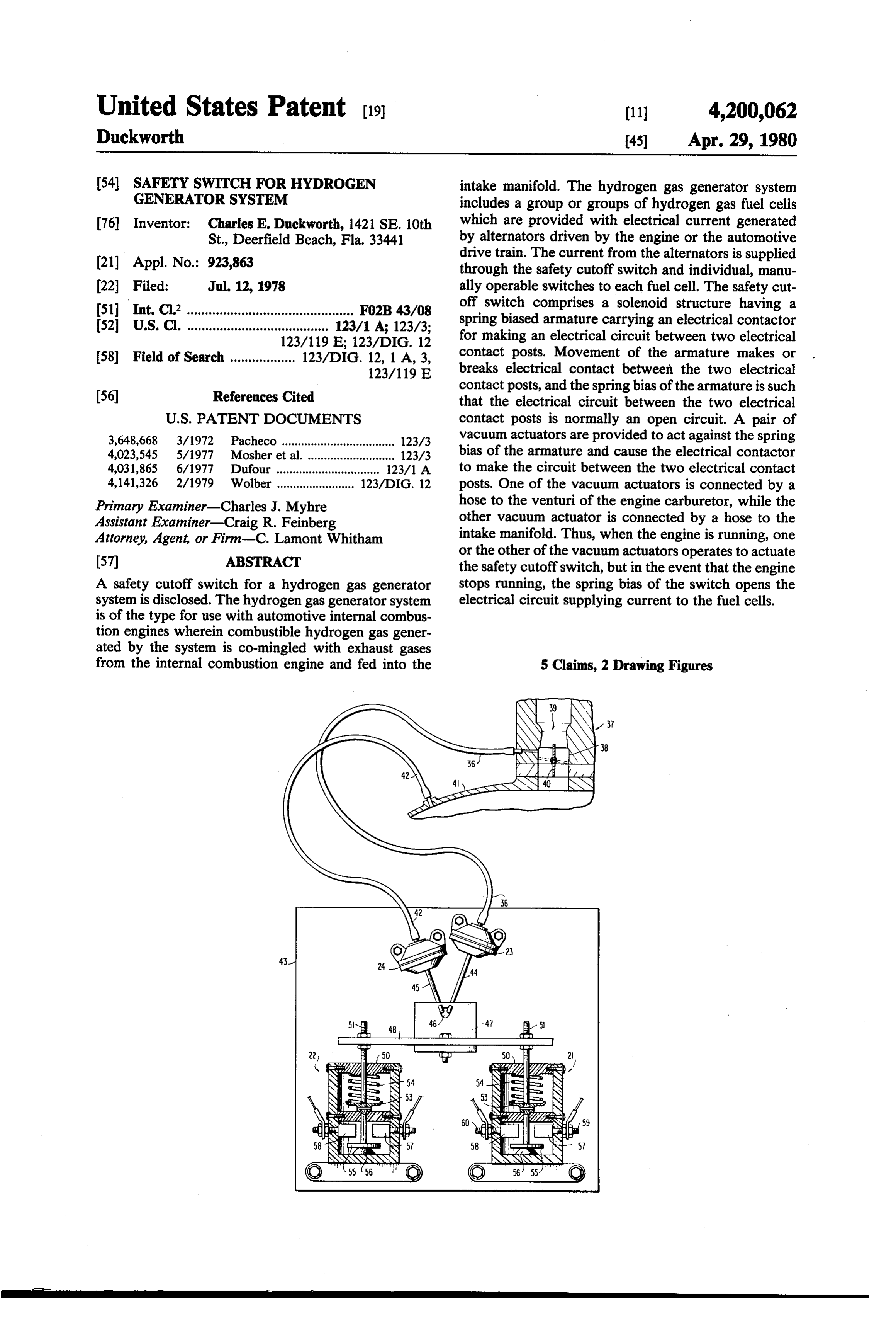
United States Patent (19) 11) 4,200,062 Duckworth 45) Apr. 29, 1980 54 SAFETY SWITCH FOR HYDROGEN intake manifold. The hydrogen gas generator system GENERATOR SYSTEM includes a group or groups of hydrogen gas fuel cells 76 Inventor: Charles E. Duckworth, 1421 SE. 10th which are provided with electrical current generated St., Deerfield Beach, Fla. 33441 by alternators driven by the engine or the automotive (21) Appl. No.: 923,863 drive train. The current from the alternators is supplied through the safety cutoff switch and individual, manu (22 Filed: Jul. 12, 1978 ally operable switches to each fuel cell. The safety cut 51) Int. C.’.............................................. FO2B 43/08 off switch comprises a solenoid structure having a 52 U.S. C. ....................................... 123/1A; 123/3; spring biased armature carrying an electrical contactor 123/119 E; 123/DIG. 12 for making an electrical circuit between two electrical 58) Field of Search .................. 123/DIG. 12, 1 A, 3, contact posts. Movement of the armature makes or 123/119 E breaks electrical contact between the two electrical
contact posts, and the spring bias of the armature is such that the electrical circuit between the two electrical
3,648,668 3/1972 Pacheco ................................... 123/3 vacuum actuators are provided to act against the spring 4,023,545 5/1977 Mosher et al. ... 123/3 bias of the armature and cause the electrical contactor 4,031,865 6/1977 Dufour ................................ 123/1 A to make the circuit between the two electrical contact 4,141,326 2/1979 Wolber ........................ 123/DIG, 12 posts. One of the vacuum actuators is connected by a Primary Examiner-Charles J. Myhre hose to the venturi of the engine carburetor, while the Assistant Examiner-Craig R. Feinberg other vacuum actuator is connected by a hose to the Attorney, Agent, or Firm-C. Lamont Whitham intake manifold. Thus, when the engine is running, one
or the other of the vacuum actuators operates to actuate the safety cutoff switch, but in the event that the engine
A safety cutoff switch for a hydrogen gas generator stops running, the spring bias of the switch opens the system is disclosed. The hydrogen gas generator system electrical circuit supplying current to the fuel cells. is of the type for use with automotive internal combus tion engines wherein combustible hydrogen gas gener ated by the system is co-mingled with exhaust gases from the internal combustion engine and fed into the 5 Claims, 2 Drawing Figures
SNs 2
Page 2
Drawing sheet — no readable text.
Page 3
Drawing sheet — no readable text.
Page 4
should. Neither Mosher et al. or Newkirk et al., how
SAFETY SWITCH FOR HYDROGEN GENERATOR ever, provide a fail-safe system which will quickly and SYSTEM positively cause the generation of hydrogen to cease in the event that the engine stops running.
SUMMARY OF THE INVENTION
The present invention generally relates to hydrogen gas generator systems for use as supplemental fuel It is therefore an object of my invention to provide a sources for automotive internal combustion engines safety cutoff switch for a hydrogen gas generator sys and, more particularly, to a safety cutoff switch for 10 tem of the type used to supply hydrogen gas as a supple stopping the production of hydrogen by the fuel cells mental fuel to automotive internal combustion engines when the engine stops running. and, more particularly, to such a safety cutoff switch The generation of hydrogen as a supplemental fuel which is fail-safe, assuring the instantaneous and posi for internal combustion engines has been well known tive cessation of hydrogen production when the engine for many years. For example, U.S. Pat. No. 1,632,285 to stops running.
Georgi discloses a gas generator wherein a combustible 5 My safety cutoff switch is particularly useful in a gas is formed from a hydrogenator and co-mingled with hydrogen gas generating system wherein one or more exhaust gases from an internal combustion engine and groups of hydrogen gas fuel cells are provided with fed into the carburetor inlet manifold. Suitable valves electrical current generated by alternators driven by the prevent a back pressure flow from the engine, and engine or the automotive vehicle drive train. The cur means are provided for the use of a rheostat and amme 20 rent from the alternators is supplied through the safety ter to control the supply of current to the electrodes of cutoff switch and individual, manually operable the hydrogenator. More recently, U.S. Pat. No. switches to each fuel cell. A separate ammeter may be 4,023,545 to Mosher et al. discloses an energy means for provided for each group of fuel cells, and the ammeters internal combustion engines utilizing a hydrogenator as and manually operable switches may be conveniently an auxiliary system to enhance the combustion of the 25 located on the instrument panel of the automotive vehi fuels used within the engine. Suitable valves are ar cle.
ranged within the manifold section for supplying the According to the present invention, the safety cutoff hydrogen and oxygen gases. switch comprises a solenoid structure having a spring The use of hydrogen as an auxiliary fuel has been attractive for many years and is now the subject of 30 biased armature which carries an electrical contactor. Linear movement of the armature causes the electrical considerable investigation because of the impending shortages of hydrocarbon fuels. In its simplest form, a contactor contact to contact or move away from two electrical posts, thereby making or breaking an electrical hydrogen generating fuel cell is simply an electrolytic cell which produces hydrogen and oxygen by the elec circuit connected to the two electrical contact posts. trolysis of water. All that is needed is a source of electri 35 The spring bias on the armature is such as to make the armature move the electrical contactor out of contact cal current to supply the electrolytic cell, and this can be provided by means of an alternator driven by the with the two electrical contact posts so that the electri engine or the drive train of the automotive vehicle. cal circuit connected thereto is normally opened. A pair There are, however, certain dangers in the use of hy of vacuum actuators are mechanically connected to the drogen as a fuel due to its being so highly combustible. armature of the switch and act against the spring bias of Because of this, it is preferable to consume the hydro the armature to cause the electrical contactor to come gen gas as a fuel as it is generated rather than accumu into contact with the two electrical contact posts and late and store it. make the electrical circuit connected thereto. One of In my earlier U.S. Pat. No. 4,068,628, I disclosed a the vacuum actuators is connected by a hose to the multi-cylinder, gasoline burning, internal combustion 45 venturi of the engine carburetor, while the other vac engine which is converted by modification of the intake uum actuator is connected by a hose to the intake mani and exhaust manifolds to an engine having designated fold. As is well known, when the throttle of the carbu exhaust burning cylinders which burn the exhaust gases retor is closed, the intake manifold of the engine is at a that are expelled from the gasoline burning cylinders. low pressure or high vacuum, whereas the venturi of To this system, I have added a hydrogen generating 50 the carburetor is at a high pressure or low vacuum. system which supplies the highly combustible hydrogen Thus, when the engine is running and the throttle is gas to the intake manifold for the designated exhaust closed, the vacuum actuator connected to the intake burning cylinders. While this system works quite well, manifold operates to move the switch armature against it is necessary to consider the safety of the system the spring bias so as to bring the electrical contactor should it be in general public use. For example, in the 55 into contact with the two electrical posts of the switch. event of an accident or for some reason the engine stops On the other hand, when the throttle valve is open, the running so that the hydrogen generated is not consumed intake manifold is at a high pressure or low vacuum, in the normal operation and functioning of the automo whereas the carburetor venturi is at low pressure or bile, it is necessary to provide some means by which the high vacuum. Thus, when the engine is running and the production of the hydrogen is stopped when the engines throttle valve is in the open position, the vacuum actua stops running. tor connected to the carburetor venturi acts against the The above-referenced patent to Mosher et al. also spring bias of the switch armature to bring the electrical recognizes that, as a prerequisite to the generation of contactor into contact with the two electrical posts of hydrogen for supply to the intake manifold, the engine the switch. Thus, when the engine is running, one or the must be operating. U.S. Pat. No. 3,710,770 to Newkirk 65 other of the vacuum actuators operates to actuate the et al. discloses a pressure switch which is used as a safety cutoff switch so as to make the electrical circuit safety switch to shut off the supply of hydrogen to the which is connected to the two electrical posts, but in the engine in the event that the engine does not start as it event that the engine stops running, the spring bias of

Page 5
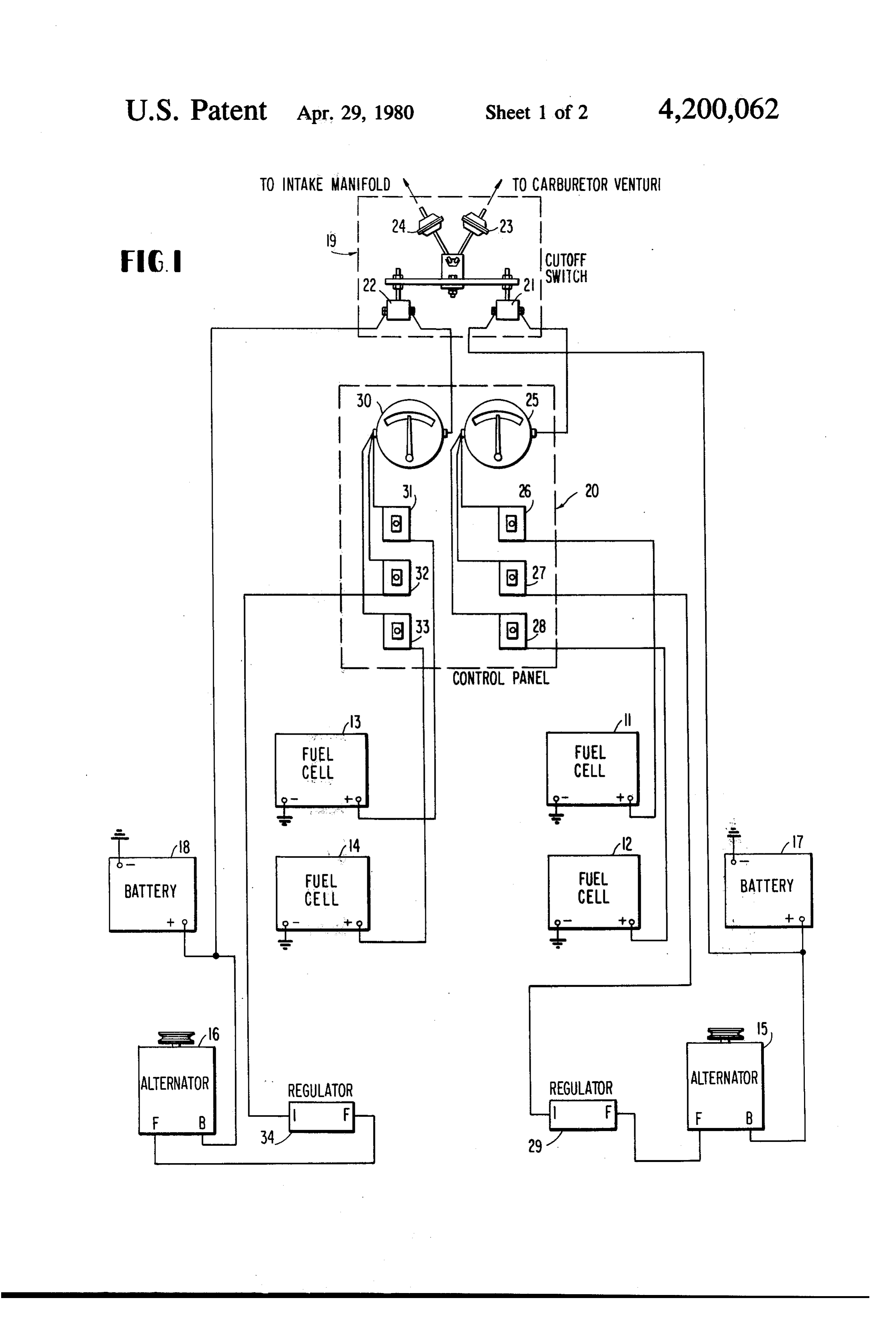
the switch armature opens the electrical circuit and turned on or off by means of manually operable switch stops the supply of current to the fuel cells. 32. But, again, when the alternator 16 is turned off by BRIEF DESCRIPTION OF THE DRAWINGS means of manually operable switch 32, current is still supplied to fuel cells 13 and 14 by battery 18.
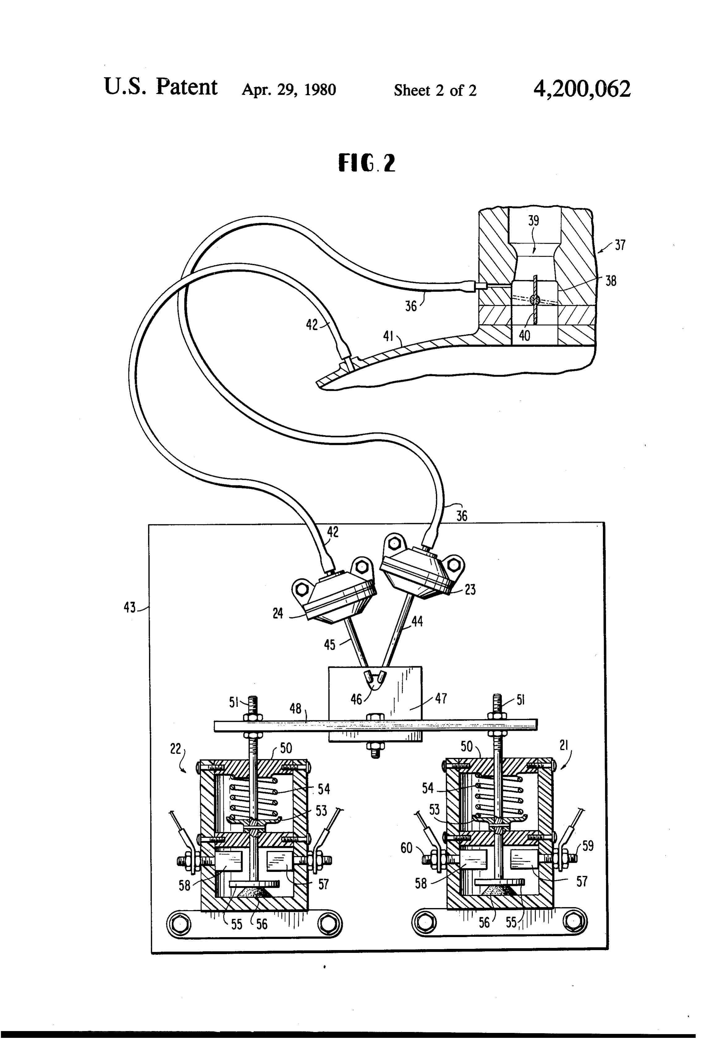
Other objects, aspects and advantages of the inven- 5 It will be appreciated that if only one group of fuel tion will be better understood from the following de cells is used, then only one alternator, battery, solenoid tailed description of a preferred embodiment with refer switch structure, ammeter and group of manually oper ence to the accompanying drawings, in which: able switches are required. Conversely, each additional FIG. 1 is a schematic diagram showing a hydrogen group of fuel cells is preferably provided with its own generating system using the safety cutoff switch accord 10 alternator, battery, solenoid switch structure, ammeter ing to my invention; and and group of manually operable switches. FIG. 2 is a detailed view, partially in cross section, of While the control panel 20 provides manual switch a preferred embodiment of the safety cutoff switch control of each one of the fuel cells and each one of the according to the invention. alternators, the purpose of this invention is provide a DESCRIPTION OF THE PREFERRED safety cutoff switch which will ensure that current to all EMBODIMENT of the fuel cells will be interrupted when the engine is not running or ceases to run as may happen, for exam
Referring now to the drawings and, more particu ple, in an accident. Especially under the emergency larly, to FIG. 1, there is shown a hydrogen gas genera conditions that may be presented in the event of an tor system comprising two groups of fuel cells 11, 12 20 accident, it is imperative that there be a cessation of the and 13, 14. The fuel cells in each group are electrically generation of hydrogen which is highly flammable. The connected in parallel and supplied with current gener safety cutoff switch 19 provides a fail-safe control, en ated by respective alternators 15 and 16. The alternators suring that current is cut off to each of the fuel cells 15 and 16 can be driven by a crankshaft pulley provided when the engine is not running.
on the engine, or, in one actual embodiment of the sys 25 Reference is now made to FIG. 2 which shows in tem, the alternators 15 and 16 are driven by a pulley more detail the structure of the safety cutoff switch attached to the differential in the drive train of the auto according to the invention. The vacuum actuator 23 is motive vehicle. The alternators 15 and 16 are energized connected by a hose 36 to the venturi area of a carbure by batteries 17 and 18, respectively, and supply current tor 37 for the automobile engine. The carburetor 37 is through the cutoff switch 19 and the control panel 20 to 30 shown only very schematically but comprises a barrel each of the respective groups of fuel cells 11, 12 and 13, 38 having a venturi area 39 and a throttle valve 40. 14. The cutoff switch 19 will be described in more detail Carburetor 37 is mounted on the intake manifold 41 of with reference to FIG. 2, but generally comprises two the engine. The vacuum actuator 24 is connected by solenoid switch structures 21 and 22 operated by a pair hose 42 to the intake manifold 41. The throttle 40 is of vacuum actuators 23 and 24 acting through a control 35 shown in the full open position in the figure, and, as is link and actuator bar assembly. One solenoid switch well known, this results in a low pressure or a high structure 21 or 22 is provided for each group of fuel vacuum condition in the venturi area of the carburetor cells 11, 12 or 13, 14. The vacuum actuator 23 is con 37 and a high pressure or low vacuum condition in the nected by a hose to the carburetor venturi, while the intake manifold 41. As a result, the vacuum actuator 23 vacuum actuator 24 is connected by a hose to the intake 40 is actuated, but the vacuum actuator 24 is not. On the manifold of the engine. other hand, when the throttle valve 40 is in the full The control panel 20 comprises an ammeter and a closed position, there results a high pressure or low bank of manually operable switches for each group of vacuum condition in the venturi area 39 of the carbure fuel cells. Thus, current generated by alternator 15 for tor 37 and a low pressure or high vacuum condition in fuel cells 11 and 12 is supplied via the solenoid switch 45 the intake manifold 41. Under this condition, the vac structure 21 to an ammeter 25 and thence in parallel to uum actuator 24 is actuated, but the vacuum actuator 23 switches 26 and 28 which supply current to fuel cells 11 is not. The important point to be understood is that one and 12, respectively. In addition, a switch 27 is con or the other of the vacuum actuators 23 or 24 will be nected between the ammeter 25 and a voltage regulator actuated when the engine is running; however, when 29 which controls the current returned to the field 50 the engine ceases to run, neither of the vacuum actua winding of the alternator 15. Thus, by means of manu tors 23 or 24 are actuated.
ally operable switches 26 and 28, it is possible for the The vacuum actuators 23 and 24 are suitably operator to connect or disconnect the supply of current mounted to a fixed plate 43, but may just as easily be to the fuel cells 11 and 12, and, by means of switch 27, mounted to the fire wall of the engine compartment. it is possible for the operator to turn off alternator 15. 55 The actuators 23 and 24 operate through the link and However, it will be observed that by turning off alterna bar assembly to control the solenoid switch structures tor 15, current will still be supplied to fuel cells 11 and 21 and 22. More specifically, vacuum actuator 23 is 12 by battery 17. provided with a hooked actuator rod 44, and vacuum Similar connections are made for the second group of actuator 23 is provided with a hooked actuator 45. Both fuel cells 13 and 14. Specifically, battery 18 energizes 60 of the hooked actuator rods 44 and 45 engage a slot 46 alternator 16 which supplies current through the sole in plate 47. The plate 47 is attached to a bar 48 made of noid switch structure 22 to ammeter 30. Switches 31, 32 an electrical insulating material, such as a suitable plas and 33 are connected in parallel to ammeter 30, tic. One end of the bar 48 is connected to the armature switches 31 and 33 being connected to supply fuel cells of switch solenoid structure 21, while the other end of 13 and 14, while switch 32 is connected to supply cur bar 48 is connected to the armature of solenoid switch rent via voltage regulator 34 to alternator 16. Fuel cells structure 22.
13 and 14 can be turned on or off by means of manually The solenoid switch structures 21 and 22 are identi operable switches 31 and 33, and alternator 16 can be cal, and, therefore, the description of these structures
Page 6
will be made only with reference to solenoid switch failure of an alternator or a battery. For example, if the structure 21, it being understood that the same descrip battery normally used for the vehicle starter and igni tion applies to solenoid switch structure 22. The sole tion system became completely discharged and the noid switch structure 21 has an outer shell case 49 made starter therefore could not start the vehicle, a switch of an electrical insulating material, such as a suitable 5 could be provided between the vehicle system battery plastic. This shell case 49 is fixedly attached to the plate and one of the hydrogen fuel cell auxiliary batteries (17 43 or directly to the fire wall of the engine compart or 18) which would enable the starter to function. It ment. The top of the case 49 is closed with a cover plate will be appreciated, however, that whatever form the 50 having an aperture therein through which the arma electrical system takes, the invention provides a fail-safe ture shaft 51 passes to the attachment at the end of bar 10 safety cutoff switch which assures that the generation of 48. A second plate 52 similar to the cover plate 50 is hydrogen by the fuel cells will stop immediately upon positioned within the case 49 and also has an aperture the cessation of the running of the engine. through which the shaft 51 of the armature passes. The What is claimed is:
plates 50 and 52 are preferably made of a plastic mate 1. A safety cutoff switch for use in a hydrogen gener rial and act as bearings for the axial movement of the 15 ating system supplying hydrogen gas as a supplemental armature shaft 51. The armature shaft 51 is provided fuel to an internal combustion engine, said hydrogen with a spring retainer plate 53 which is fixedly attached generating system comprising at least one group of fuel thereto. A coil spring 54 is positioned between the cells connected through said safety cutoff switch to a spring retainer 53 and the under surface of the top cover source of electrical current and said internal combustion plate 50. The spring 54 biases the armature shaft 51 for engine having an intake manifold and a carburetor com movement in a downward direction as viewed in the 20 prising a venturi and a throttle valve, said carburetor figure. At the lowermost end of the armature shaft 51, being attached to said intake manifold for supplying a there is fixedly attached an electrical contactor 55. The fuel and air mixture to said engine, said safety cutoff electrical contactor may be made of brass or other suit switch comprising:
able good electrical conductor. Just below the electrical a first vacuum actuator means connected by a hose to contactor 55 is a resilient bumper 56 made of rubber or 25 said carburetor venturi;
other elastomeric material. The purpose of the bumper a second vacuum actuator means connected by a hose 56 is to arrest the downward movement of the armature to said intake manifold; and shaft 51 and contactor 55 and provide quietness of oper switch means mechanically connected to both of said ation of the switch. Two electrical contact posts 57 and first and second vacuum actuators for actuation 58 are positioned within the case 49 on opposite sides 30 thereby to make an electrical connection between thereof and above the electrical contactor 55. Electrical said group of fuel cells and said source of electrical post 57 is provided with a threaded electrical terminal current when said engine is running, said switch 59 which projects through the case 49 for connection to means breaking said electrical connection in the ammeter 25 on the control panel 20, Electrical contact absence of actuation by both of said first and sec post 58 is also provided with an electrical terminal 60 35 ond vacuum actuator means. which projects through the case 49 for connection to 2. A safety cutoff switch as recited in claim 1 wherein the positive terminal of battery 17. Both the electrical said hydrogen generating system comprises a plurality contact posts 57 and 58 and their respective terminals 59 of groups of fuel cells, each group being connected and 60 may be made of brass or other suitable good through said safety cutoff switch to said source of elec electrical conductor. trical current, said safety cutoff switch having a plural In operation, when the engine is not running, the ity of switch means, one for each group of fuel cells, electrical armature shaft 51 is in its downward-most each of said switch means being mechanically con position so that the electrical contactor 55 rests on the nected in common to both of said first and second vac bumper 56 and out of contact with the electrical posts uum actuators.
57 and 58. However, once the engine is running, one or 3. A safety cutoff switch as recited in claim 1 wherein the other of the vacuum actuators 23 or 24 will be actu 45 said switch means comprises spring bias means for ated so that their respective actuator shafts 44 or 45 will breaking said electrical connection in the absence of exert an upward force on the plate 47, thereby pulling actuation by both of said first and second vacuum actua armature shaft 51 upwardly against the bias spring 54 so to means.
that the electrical contactor 55 will contact the electri 4. A safety cutoff switch as recited in claim 1 wherein cal posts 57 and 58, thereby making the circuit between 50 said switch means comprises:
the positive terminal of battery 17 and the ammeter 25. an armature shaft mechanically connected to, but Should the engine stop running, then neither of the electrically insulated from, said first and second vacuum actuators 23 or 24 will be actuated, with the vacuum actuator means for movement thereby; result that no upwardly directed force will be applied to an electrical contactor fixedly attached to said arma the plate 47 so that the bias spring 54 will cause the 55 ture shaft;
armature shaft 51 to move downwardly, thereby break first and second electrical contact posts positioned for ing the circuit between the positive terminal of battery mating contact with said electrical contactor upon 17 and the ammeter 25. movement of said armature shaft by one or the While a preferred embodiment of the invention has other of said first and second vacuum actuators, been described, it will be understood by those skilled in said first and second electrical contact posts being the art that the various modifications and arrangements electrically connected to said group of fuel cells can be made without departing from the scope of the and to said source of current, respectively; and invention. The system as described provides electrical spring bias means acting on said armature shaft in a current for the independent operation of multiple manner to urge said electrical contactor to move groups of hydrogen fuel cells. It is preferred to have this out of contact with said first and second electrical electrical system independent of the vehicle electrical 65 contact posts.
system, but, if desired, the two electrical systems could 5. A safety cutoff switch as recited in claim 4 wherein be connected in parallel to provide a unified electrical said armature shaft moves linearly. system for the vehicle. This could be helpful in case of t is
Provenance
- Collection
- Cited prior art
- Original PDF
- patentimages.storage.googleapis.com →
- Filed
- 1978-07-12
- Pages
- 6
- Method
- pdftotext (the PDF's own text layer) + pdftoppm 300dpi page scans
- Source
- Google Patents bibliographic record
- Granted
- 1980-04-29
- Inventors
- Charles E. Duckworth
- Transcribed from
- patentimages.storage.googleapis.com →