patent · US2538222
Safety control gas burner system
16 January 1951
Page 1
Drawing sheet — no readable text.
Page 2
Patented Jan. 16, 1951 . . . .. . 2,538,222
UNITED STATES PATENT OFFICE
SAFETY CONTROL, GAS BURNER, SYSTEM
Jack T. Wilson, Milwaukee, Wis., assignor to
Perfex Corporation, Milwaukee, Wis., a corpo ration of Wisconsin
Application May 4, 1945, Serial No. 591,917
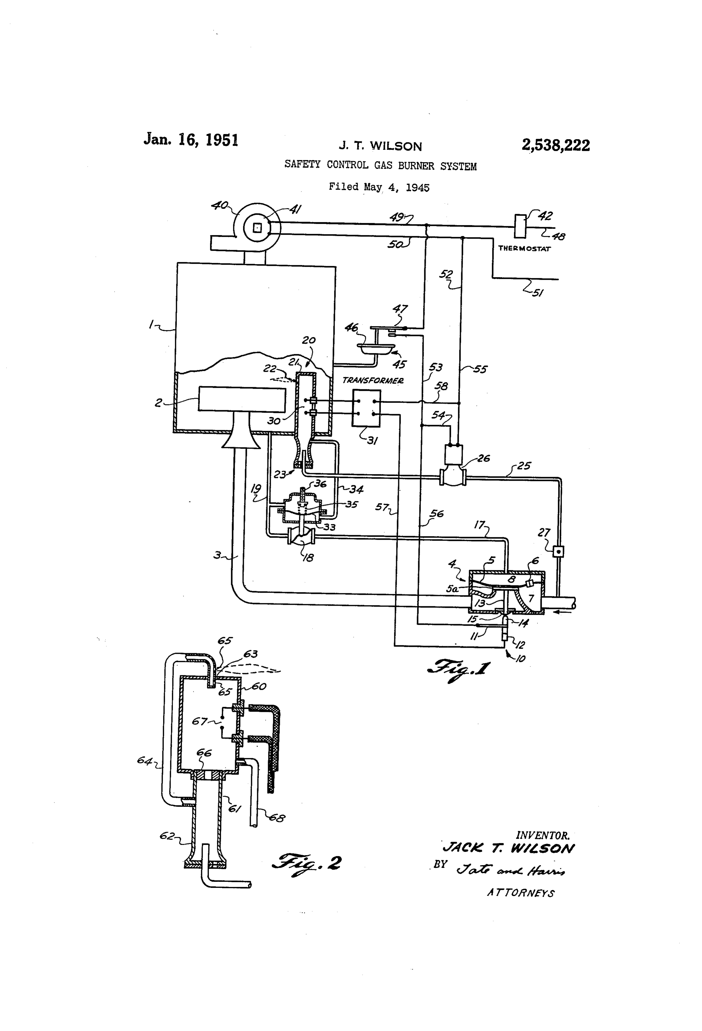
This invention relates to burner control SyS which permits gas to bleed from the inlet cham tems, and more particularly to burner control ber 7 into the space 8 above the diaphragm, this Systems of the type in which the burner is ignited Serving to hold the valve in closed position. by a gas pilot. The valve 4 is provided with an electric Switch In gas fired devices it is desirable to prevent 5 O. This switch is illustrated diagrammatically the flow of gas to the main burner when the pilot as including a flexible switch blade which is not burning. In the past this result has been carries a contact adapted to engage and disen obtained by the use of a thermal responsive de gage a stationary contact 2. The free end of vice which is located at the pilot burner so as the fiexible blade is actuated in accordance to be heated by the pilot flame. These devices with the position of the valve, for example by are inherently slow operating and are difficult a plunger 3 which is attached to the valve and expensive to manufacture. member and which operates a Switch actuating It is a primary object of the present invention button 4 through a suitable sealing diaphragm to provide a device which responds rapidly to the 5. The Switch O is arranged so that it is closed presence or absence of combustion at the pilot 5 when the valve 4 is closed and opens when the burner and which is also simple and positive in Valve 4 openS.
construction. The diaphragm Valve 4 is provided with a feed It is a further object of the invention to pro line which is connected to a control valve 8, vide a device of this character which eliminates which in turn is connected by a tube 9 with the the necessity of a thermal responsive device lo interior of the furnace . The control valve 8 cated at the pilot burner. is controlled in accordance with the presence or In accordance with the present invention, a absence of combustion within the pilot burner 20. Special pilot burner is provided in which a com Referring to the pilot burner 20, this burner bustible mixture is burned within a confined consists of a closed tube 2 which is provided with Space. The volume of gases issuing from the 25 an Orifice 22 arranged so that it projects a flame burner increases when combustion takes place from the pilot burner to the main burner 2 for within the burner due to expansion of the gases lighting the same. The pilot burner is shown by the temperature of combustion. In the pres as extending from the bottom of the furnace ent invention a device exterior of the furnace is and being provided with a gas-air mixing cham provided which responds to the increase in pres 30 ber 23 at its lower end. Gas is supplied to the Sure in the special pilot burner. This responsive pilot through a gas line 25 which is controlled device thus indicates the presence or absence of by a solenoid valve 26. The gas line 25 is pro combustion in the burner. Due to the fact that vided With a Suitable manual valve 27 for con the device responds to pressure of gases which trolling the flame in the pilot burner. The pilot varies instantly when combustion takes place, burner 20 is also provided with ignition elec the device is very quick acting. trodes 30, these electrodes being located inside Other objects of the invention will appear from the enclosed chamber of the burner and having the following description and the appended leads which extend through suitable insulating claims. bushings in the side wall of the pilot burner. For a complete disclosure of the invention, 40 These electrodes are attached to the secondary reference is made to the accompanying drawings of an ignition transformer 3. in which, In Operation, the gas-air mixture supplied to Fig. 1 shows one form of gas control system the pilot burner burns partially within the burner. embodying the invention; and The supply of gas to the burner is regulated so Fig. 2 shows a preferred form of pilot con 45 that all of the mixture does not burn within Struction. the pilot, thereby causing a jet of flame to pass Referring to Fig. 1, reference character in through the orifice 22 to the main burner 2 for dicates a furnace having a main gas burner 2, igniting the main burner. When the pilot burner which is Supplied with gas through a gas line 3, is ignited, the temperature of combustion causes which is controlled by a valve 4. The valve 4 : the volume of gases discharged from the burner anay be of the diaphragm type having a dia to be several times the volume of the gas-air phragm 5 which carries a valve member 5d. con mixture entering the burner. In accordance with Crolling the flow of gas from the inlet to the the present invention, the increase in pressure outlet of the valve. The particular valve illus caused by combustion is utilized as an indication trated is of the type having a bleeding orifice 6 i55 that the pilot is burning. This change in press
Page 3
sure of gases may be detected in any suitable which supplies gas to the pilot burner 20. Si manner. Preferably the pressure increase is multaneously the ignition transformer is ener measured by a device which responds to the gized through the switch 0 which is closed at pressure differential across the restricted outlet this time, and this causes a spark to occur be from the pilot chamber. This may be done by tween the electrodes 30. As a result a gas-air means of a diaphragm 33, the lower side of which mixture is Supplied to the interior of the pilot is subjected to the pressure within the pilot burner and this mixture is ignited by the electric burner by means of a tube 34. The upper side Spark. When the mixture ignites, the tempera of this diaphragm responds to the pressure On ture of combustion causes the volume of gases to the discharge side of the orifice 22 through a O expand, thereby increasing the pressure drop suitable line, such as the line 9 which OpenS across the discharge 22 from the pilot burner. into the interior of the furnace. The diaphragm This increase in differential is detected by the 33 serves to operate the control valve 8 and is diaphragm 33 which opens the control valve 8. biased downwardly by a spring 35 having tension This permits gas to bleed from the chamber 8 in adjusting means 36. This adjusting means is ad 5 the main diaphragm valve, thereby causing the justed so that when the pressure drop across ori main valve to open and supply gas to the main fice 22 is below that indicating combustion within burner. This gas is ignited by the jet of flame the pilot burner, the control valve 8 is held in projecting from the pilot burner. closed position. However, when combustion takes 20 As the gas valve opens, it permits the switch place within the pilot burner, the pressure in O to open, thereby breaking the circuit to the creases within the burner and this increase in ignition transformer. Thus when combustion pressure urges the diaphragm 33 upwardly takes place within the pilot burner, the ignition against the biasing spring 35 for opening the device is cut off and gas is supplied to the main control valve 8. Thus when the volume of gases burner. The burner will now operate until the leaving the pilot increases due to combustion 25 thermostat 48 becomes satisfied. When this within the pilot, the diaphragm 33 causes the Occurs, it deemergizes the blower 40 and also de energizes the Solenoid valve 26. The flame with control valve to Open.
While the invention is not limited to subat in the pilot burner becomes extinguished, thereby causing the pressure within the burner to de mospheric systems, it is intended primarily for 30 Crease.
such systems. The furnace is shown as being The diaphragm 33 responds to this de provided with a suction fan 40 driven by an elec Crease in pressure by closing the control valve 8. This prevents bleeding of gas from the cham tric motor 41, this fan serving to draw a partial ber 8 of the main diaphragm valve, thereby caus vacuum within the furnace. The remainder of the complete control system illustrated includes a 35 ing this valve to close and stop the flow of gas to the main burner.
room thermostat 42 which stops and starts the It will be noted that due to the control of the fan and which also controls the ignition trans main gas valve by the pressure in the pilot burner, former 31 and the solenoid valve 26. Preferably the main gas valve can never be open without a suction responsive device 45 is wired in series combustion being present within the pilot burner. with the thermostat so as to prevent the burner This insures that the gas supplied to the main from operating unless the fan 40 has created a 40 burner will always be ignited.
partial vacuum within the furnace. This device Figure 2 is shown as including a diaphragm 46 which re sponds to pressure within the furnace and which With the pilot burner construction shown in operates a Switch 47. Fig. 1, it is necessary to adjust the Supply of the
gas-air mixture to the burner So that complete
Operation combustion does not take place within the burner. With the parts in the positions shown, the This is necessary so that a sufficient quantity of thermostat 42 is satisfied and the blower 40 is unburned gases pass through the outlet 22 so out of operation. The solenoid valve 26 and ig 50 Theas to provide a jet of flame Outside the pilot. nition transformer 3 are both deemergized. No pilot burner construction shown in Fig. 2 pressure differential is present across the dia insures that a Satisfactory flame will be present phragm 33 and the pilot valve f8 is closed. This of for igniting the main burner almost irrespective has caused the main gas valve 4 to be in closed burner. the gas-air mixture Supplied to the pilot position, which in turn results in the switch 0 Referring to Fig. 2, the pilot burner includes being in closed position. When the thermostat a circular enclosure 60 which is provided at its calls for heat it completes a circuit from line wire lower end with a feed tube 6 extending from 48 through the thermostat, wire 49, biower motor a gas-air mixer 4, and wire 50 to the line 5. Operation of the with a restricted62.opening
The enclosure 60 is provided 63 at its upper end.
blower 40 creates a suction in the furnace which O An ignition tube 64 extends from the supply tube causes the suction responsive device 45 to close 6 to the top of the burner and then back into the switch 47. This energizes the solenoid valve the opening 63. This tube is closed at its end 26 and simultaneously energizes the ignition and is provided with orifices 65. Preferably a transformer 3. The circuit for the solenoid valve extends from wire 49, through wire 52, 65 air supplyrestrictor
Suitable 66 is located between the gas tube and the interior of the burner 60 switch. 47, wire 53, wire 54, solenoid valve 26 and so as to prevent the flame from passing back wire 55 back to line wire 5. The circuit for into tube 6. The enclosure 60 is provided with the ignition transformer extends from wire 53 electrodes 67 for igniting the gas and is also through wire 56, switch 0, wire 57, ignition trans provided with a tube 68 which leads back to former 3 and wires 58 and 55 to line wire 5. 70 the pressure responsive device. With the ar From the foregoing it will be seen that when rangement shown in Fig. 2, a portion of the the room thermostat calls for heat it starts the gas Supply is burned within the enclosed cham blower, which Creates a suction in the furnace ber So as to provide an indication of whether . The control 45 responds to this suction and or not the pilot burner is ignited. Another por closes a circuit directly to the Solenoid valve 26 5 tion of the gas-air mixture is carried up to the
Page 4
outlet 63 from the pilot burner and issues through 5. A safety pilot for a main burner comprising Orifices 65. The hot gases of combustion issuing an enclosed chamber having a restricted outlet, from the pilot burner insure that these jets will means for Supplying a combustible mixture to be ignited. Inasmuch as these jets are supplied the chamber and for causing at least a portion of With a fresh gas-air mixture which is independent 5 the mixture to burn within the enclosed cham of the burning within the enclosure 60, it is ber, a nozzle located adjacent the outlet, means possible for complete combustion to take place for Supplying fuel to said nozzle, said nozzle within the enclosure and still have a satisfactory being adapted to project a jet of fuel therefrom jet of flame issue from the pilot for lighting the in proximity to said outlet so as to be ignited main burner. 10 by hot gases leaving said outlet, said jet serving From the foregoing it will be seen that the to light the main burner. present invention provides a gas safety pilot 6. A safety pilot for a main burner compris which does not require the use of any thermal ing an enclosed chamber having a restricted out element or thermocouple within the furnace. It let, means for Supplying a combustible mixture to will also be apparent that the present invention, the chamber and for causing at least a portion of by responding to increases and decreases in pres sure within the pilot burner, will respond quickly the mixture to burn within the enclosed cham ber, and secondary pilot burner means for light to presence or absence of combustion in the ing the main burner, said secondary means being burner. The invention thus provides for obtain adapted to discharge a jet of unburned fuel ad ing fast response with a simple and dependable 20 jacent said outlet for obtaining ignition from the mechanism. While I have shown and described hot gases passing from said enclosed chamber. one embodiment or application of the invention, 7. A Safety pilot for a main burner comprising it will be apparent that many changes may be an enclosed chamber having a restricted outlet, made without departing from the scope of the means for Supplying a combustible mixture to the invention. It is therefore desired to be limited 2 5 chamber and for causing at least a portion of the only by the scope of the appended claims. mixture to burn within the enclosed chamber, What is claimed is: electric ignition means within said chamber for 1. In a control system for a main burner, the igniting said mixture, and secondary pilot burn combination of, a gas pilot burner for lighting er means for lighting the main burner, said sec the main burner, said pilot burner being con ondary means being adapted to discharge a jet of structed and arranged so that at least partial unburned fuel adjacent said outlet for obtaining combustion takes place within the pilot burner ignition from the hot gases passing from said en and having a restricted outlet for the gases closed chamber.
therefrom, whereby a rise in pressure takes place within the pilot burner when it is burning, and 3 5 an8.enclosed
A safety pilot for a main burner comprising chamber having a restricted outlet, means responsive to the pressure Within the pilot means for supplying a combustible mixture to burner for controlling the main burner. the chamber and for causing at least a portion 2. In a control system for a main burner lo cated in an enclosure to be heated, a gas pilot of ber the mixture to burn within the enclosed cham thereby causing the volume of gases passing burner located in the enclosure in proximity to 40 through the outlet to increase when combustion the main burner for lighting the same, said pilot takes place, Secondary pilot burner means for burner being constructed and arranged so that lighting the main burner, said secondary means at least partial combustion takes place within the being adapted to discharge a jet of unburned fuel pilot burner and having a restricted outlet for adjacent said outlet for obtaining ignition from the gases therefrom into said enclosure, whereby 45 the hot gases passing from Said enclosed cham a differential in pressure exists between the in ber, and a control device responsive to the pres terior of the burner and the interior of the en closure when the burner is burning, and means Sure of the gases within Said chamber for con trolling the main burner.
responsive to said differential in pressure for JACK T. WILSON. controlling the main burner.
3. In a control system for a main burner, the REFERENCES CTED combination of, a pilot burner for lighting the main burner, said pilot burner comprising an The following references are of record in the apertured chamber for combustion of mixed file of this patent:
gases therein and for flame projection through UNITED STATES PATENTS said aperture, and means responsive to the pres 55 Number Name Date sure of gases in the pilot burner for controlling 1,320,936 Scott -------------- Nov. 4, 1919 the main burner. 1,803,879 Tapp -------------- May 5, 1931 4. In a control system for a main burner, in 1820,510 Tuck -------------- Aug. 25, 1931. combination, a pilot burner for igniting the main 60 2,263,896 Long -------------- Nov. 25, 1941 burner, automatic means turning the pilot burn 2,264,808 Rabinowicz -------- Dec. 2, 1941 er on and lighting the same in response to the 2,305,243 English ------------ Dec. 15, 1942 demand for heat, and means responsive to an in 2,373,326 Miller ------------- Apr. 10, 1945 crease in pressure of gasses in the pilot burner for turning on the main burner.
Provenance
- Collection
- Cited prior art
- Original PDF
- patentimages.storage.googleapis.com →
- Filed
- 1945-05-04
- Pages
- 4
- Method
- pdftotext (the PDF's own text layer) + pdftoppm 300dpi page scans
- Source
- Google Patents bibliographic record
- Granted
- 1951-01-16
- Inventors
- Jack T Wilson; Perfex Corp
- Transcribed from
- patentimages.storage.googleapis.com →