patent · US4617892
Fuel-optimizing electronic control circuit for a fuel-injected marine engine or the like
21 October 1986
Page 1 — bibliographic record
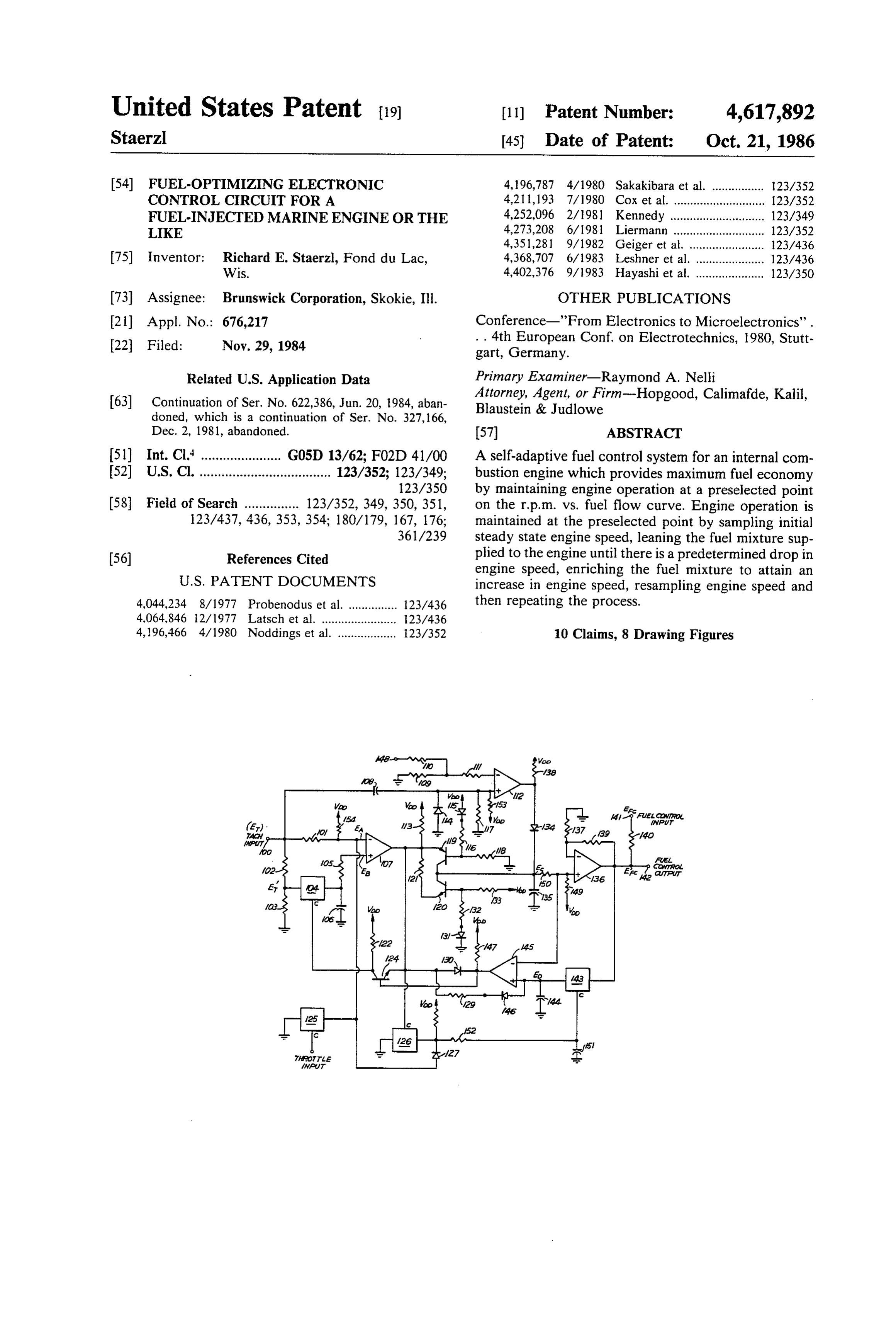
United States Patent (19) (11) Patent Number: 4,617,892 Staerzl (45) Date of Patent: Oct. 21, 1986 (54) FUEL-OPTIMIZING ELECTRONIC 4,196,787 4/1980 Sakakibara et al. ................ 123/352 CONTROL CIRCUIT FOR A 4,211,193 7/1980 Cox et al. ............................ 123/352 FUEL-INJECTED MARINE ENGINE OR THE 4,252,096 2/1981 Kennedy ............................. 123/349 LIKE 4,273,208 6/1981 Liermann ... - ... 123/352 4,351,281 9/1982 Geiger et al. ..... ... 23/436 75) Inventor: Richard E. Staerzl, Fond du Lac, 4,368,707 6/1983 Leshner et al. ... ... 123/436 Wis. 4,402,376 9/1983 Hayashi et al. ..................... 123/350 73 Assignee: Brunswick Corporation, Skokie, Ill. OTHER PUBLICATIONS 21 Appl. No.: 676,217 Conference-'From Electronics to Microelectronics'. 22 Filed: Nov. 29, 1984 . . 4th European Conf. on Electrotechnics, 1980, Stutt gart, Germany.
Related U.S. Application Data Primary Examiner-Raymond A. Nelli
Attorney, Agent, or Firm-Hopgood, Calimafde, Kalil, 63) Continuation of Ser. No. 622,386, Jun. 20, 1984, aban Blaustein & Judlowe doned, which is a continuation of Ser. No. 327, 166,
Dec. 2, 1981, abandoned. 57 ABSTRACT 51 Int. Cl." ...................... G05D 13/62; F02D 41/00 A self-adaptive fuel control system for an internal com 52 U.S. Cl. .................................... 123/352; 123/349; bustion engine which provides maximum fuel economy 123/350 by maintaining engine operation at a preselected point 58 Field of Search ............... 123/352, 349, 350, 351, on the r. p.m. vs. fuel flow curve. Engine operation is 123/437, 436, 353, 354; 180/179, 167, 176; maintained at the preselected point by sampling initial 361/239 steady state engine speed, leaning the fuel mixture sup 56) References Cited plied to the engine until there is a predetermined drop in engine speed, enriching the fuel mixture to attain an
4,044,234 8/1977 Probenodus et al. ............... 123/436 then repeating the process.
4,196,466 4/1980 Noddings et al. .................. 1.23/352 10 Claims, 8 Drawing Figures
Page 2
Drawing sheet — no readable text.
Page 3
Drawing sheet — no readable text.
Page 4
possible with prior art fuel control systems, is not com
FUEL-OPTIMIZING ELECTRONIC CONTROL patible with all types of two-cycle engines. CIRCUIT FOR A FUEL-NJECTED MARINE It is therefore a further object of the instant invention ENGINE OR THE LIKE to provide a self-adaptive fuel control system that oper ates with all engine types.
This application is a continuation of application Ser. It is another object of the instant invention to provide No. 622,386, filed 6-20-84, now abandoned, which is a a self-adaptive fuel control system that provides an continuation of Ser. No. 327, 166, filed Dec. 2, 1981, exact range of fuel mixture variation.
now abandoned. It is a still further object of the instant invention to O provide a self-adaptive fuel control system that has
FIELD OF THE INVENTION enhanced temperature stability.
This invention relates to fuel control systems for SUMMARY OF THE INVENTION internal combustion engines and more particularly to a self-adaptive fuel control system which provides maxi In accordance with the invention an internal combus mum fuel economy for an internal combustion marine 15 tion engine is operated at or near a preselected point on engine over all conditions of engine operation. the r. p.m. vs fuel flow curve, said preselected operating point providing maximum fuel economy during engine
BACKGROUND OF THE INVENTION operation.
Maximum fuel economy is now the primary goal for It is a feature of the invention that engine operation is designers of internal combustion engines in view of the 20 maintained at or near the preselected operating point by current and ever increasing cost of gasoline. sampling the fuel mixture and engine r.p.m. while at or The customary practice in designing and calibrating near a steady state operating condition.
the fuel supply systems for internal combustion engines It is a further feature of the invention that the fuel is to pre-schedule fuel flow according to some function 25 mixture is leaned after the steady state operating condi of engine operating condition as measured on the engine predetermined tion is reached, allowing engine r.p.m. to decrease a first during operation. On carburetor type engines the prin tion. amount in reponse to the leaning opera cipal measured function is usually venturi pressure, and It is a still further feature of the invention that when the fuel flow is primarily determined by this pressure engine (or depression) and secondarily the fuel flow may be 30 amount,r.the p.m. has decreased the first predetermined fuel mixture is enriched a second predeter determined by measuring various engine functions such mined amount, said second predetermined amount as r. p.m., manifold vacuum, air flows, throttle position, being designedly less than the degree of lean-out from etc., and controlling the fuel flow in accordance with the steady-state operating condition, thereby allowing some predetermined schedule. engine r.p.m. to again increase to a new steady-state Fuel control systems of the type described above 35 operating condition.
depend on prior knowledge of how the engine will The foregoing and other objects and features of this perform under all possible conditions of load and envi invention will be more fully understood from the fol ronment. Such systems, even when relatively compli lowing description of an illustrative embodiment cated and expensive, only obtain optimum performance thereof taken in conjunction with the accompaying in terms of fuel economy under a limited set of operat drawings.
ing conditions.
It is therefore a general object of the present inven BRIEF DESCRIPTION OF THE DRAWINGS tion to provide a self-adaptive fuel control system that In the drawings:
does not depend on prior knowledge of engine perfor FIG. 1 illustrates typical r. p.m. vs fuel flow curves aCe.
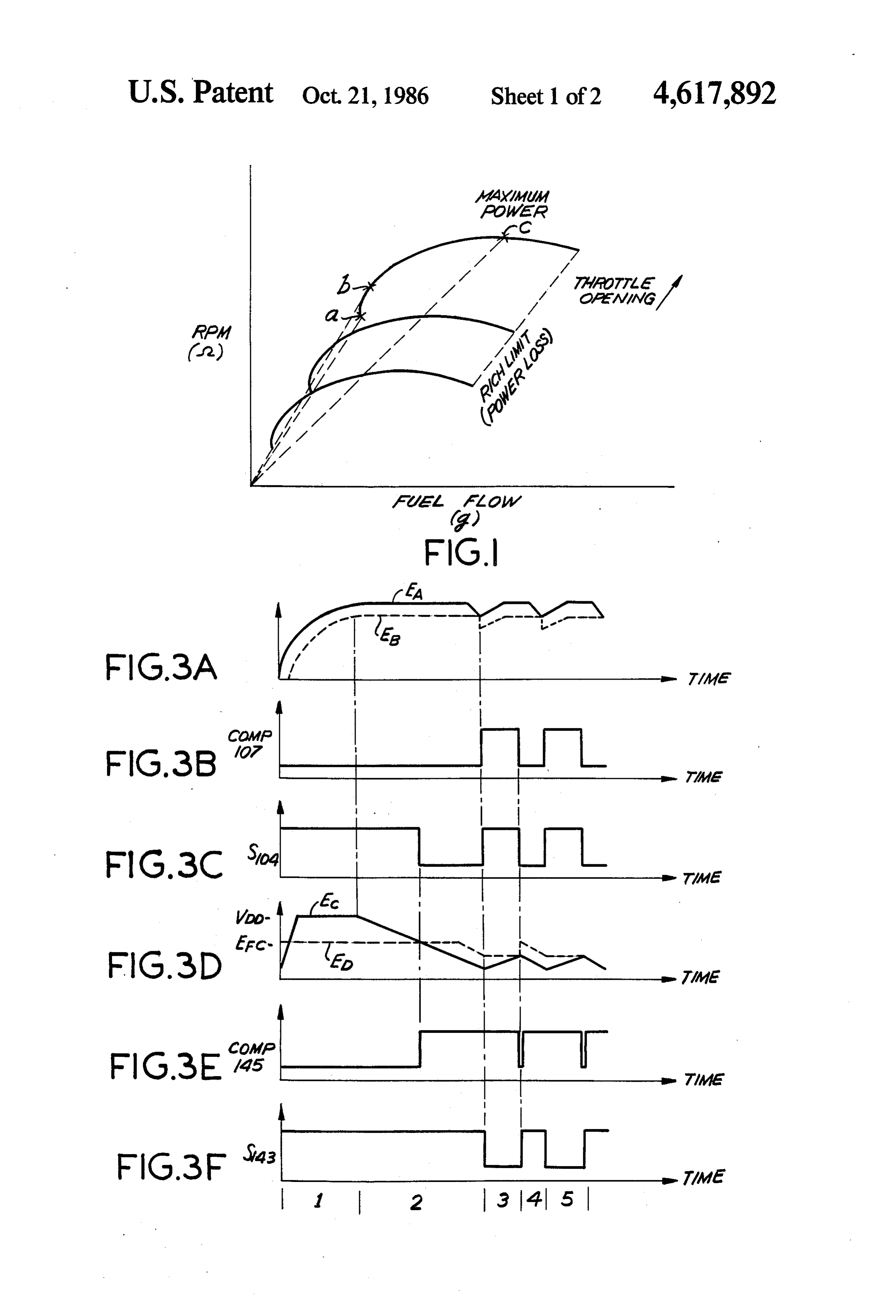
45 for an internal combustion engine;
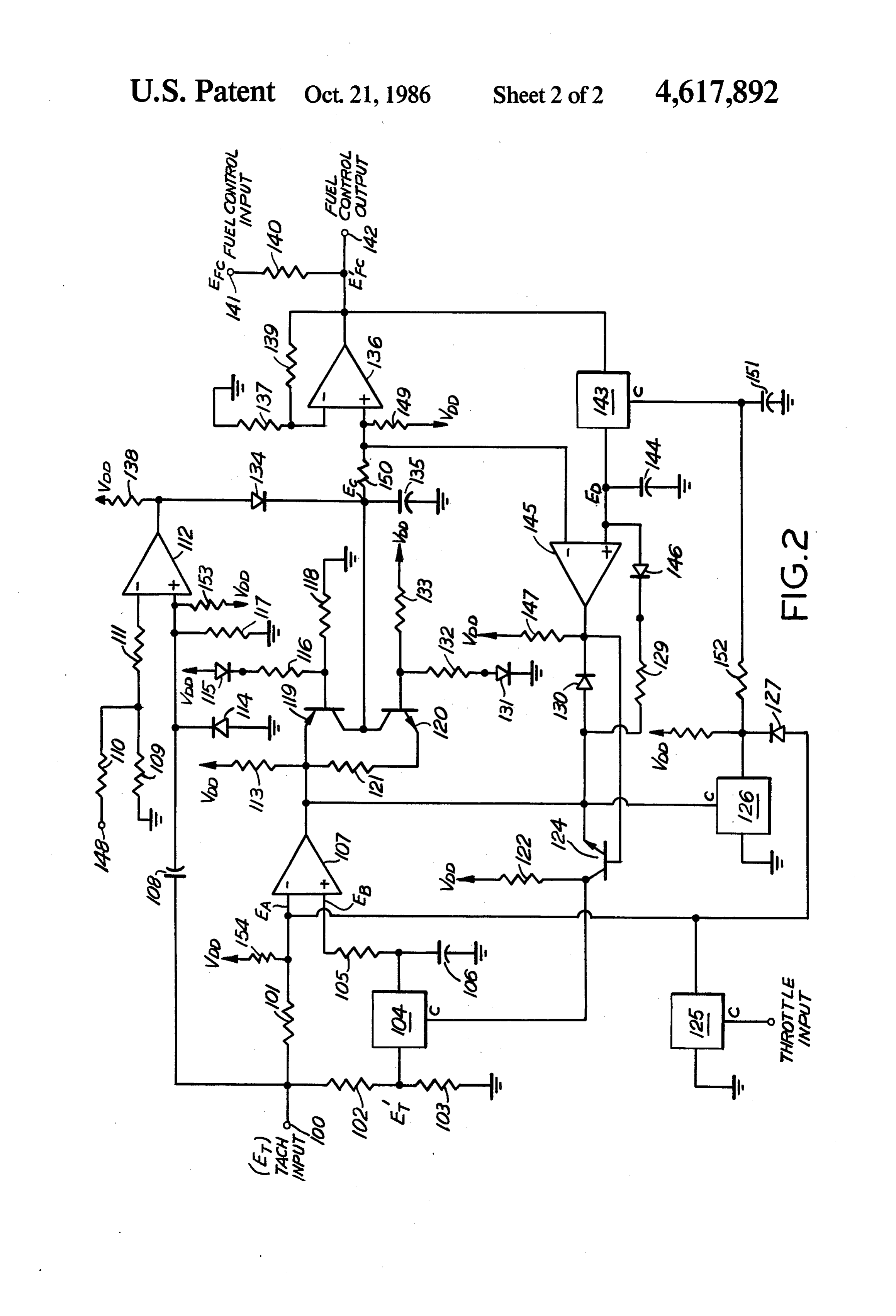
Self-adaptive fuel control systems per se are known FIG. 2 is a schematic drawing of the circuitry of the and have been discussed by Draper and Li in a publica instant tion. However, the Draper and Li system is designed near a invention preselected which maintains engine operation at or point, illustratively on one of the to provide peak power output (maximum r.p.m.) for any curves of FIG. 1; and given throttle setting and does not provide maximum 50 FIGS. 3A-3F illustrate various waveforms present fuel economy, as maximum fuel economy occurs near during operation of the circuitry of FIG. 2.
the border-line of lean misfire, not at maximum r.p.m.
*C. S. Draper and Y. T. Li, "Principles of Optimalizing Control Sys tems and the Application to the Internal Combustion Engine", Ameri DETALED DESCRIPTION can Society of Mechanical Engineers, 1951. It is known that for a given engine, operating with It is therefore a further object of the present invention 55 continuously connected load, the r.p.m. vs fuel flow to provide maximum fuel economy for any given throt curves will exhibit a relatively constant shape on the tle setting on an internal combustion engine. lean side of the curve for any given throttle setting. The A self-adaptive fuel control system that provides fuel control system of the instant invention takes advan maximum fuel economy is described in a U.S. Patent tage of this phenomenon and maintains the fuel delivery Application entitled “Programmable Fuel Economy 60 rate consistently near the lean limit while avoiding mis Optimizer For An Internal Combustion Engine" by H. fire. Since maximum fuel economy occurs near the lean E. Riordan, Ser. No. 305,900, filed Sept. 25, 1981 and limit, the instant invention is able to achieve maximum assigned to the same assignee as is the instant invention. fuel economy over all conditions of engine operation. The Riordan fuel economy optimizer provides maxi FIG. 1 shows a typical r.p.m. vs fuel flow curve for mum fuel economy by determining a rate of speed 65 each of several settings of engine throttle opening. change versus fuel flow rate change and senses the lean Points a, b and c on the top curve illustrate respectively limit of the engine on the basis of deceleration rate. This the approximate conditions of over-lean fuel flow, maxi approach, although providing many advantages not mum fuel economy, and maximum power. To the far
Page 5
right of each curve is the condition of fuel-rich limit, level d.c. output signal from comparator 112. This high with resultant power loss. The fuel control system of level signal level permits capacitor 135 to charge during the instant invention seeks to operate the associated the acceleration interval via diode 134. internal combustion engine in a range slightly to the The d.c. tachometer signal is also applied to the "-" right of point b on the r.p.m. vs fuel-flow curve, where 5 input of comparator 107. Switch 104, as well as switches the slope of the curve is always positive but the offset 125, 126 and 143, are standard CMOS sample-and-hold from the lean limit and misfire is sufficient to provide switches which are open (OFF) when the voltage at the smooth running. An operating range for the instant C (control) input is less than approximately 3 volts and invention slightly to the right of point b provides maxi closed (ON) when the C input is greater than 6 volts. mum fuel economy yet is compatible with all engine O During acceleration, switch 104 is ON which applies types and enjoys great stability over a wide range of the tachometer signal to the "+" input of comparator temperatures. 107. The tachometer signal magnitude at the "-" input The fuel control system of the instant invention is of comparator 107 is greater than the tachometer signal shown in FIG. 2. The system provides optimum fuel magnitude at the "+" input of comparator 107, due to economy by sampling the initial steady-state engine 15 the voltage divider network consisting of resistors 102, r.p.m., leaning the amount of fuel supplied until the 103 and 105 and therefore the d.c. output signal level of engine r.p.m. drops by a predetermined amount, such as comparator 107 is low during acceleration. The low 50 r.p.m., enriching the fuel mixture by a predetermined signal level output of comparator 107 turns switch 126 amount, such as 3%, resampling the engine r. p.m. and OFF which in turn results in a high level voltage then repeating the entire process. The essential func 20 (VDD) being applied to the C terminal of switch 143, tions of circuit operation are r.p.m. sampling and fuel turning this switch ON, and applying the output signal flow sampling with the circuit sensing the lean limit of from amplifier 136 to the "+" terminal of comparator engine operation on the basis of a finite r. p.m. loss. 145 and also to capacitor 144, thus allowing this capaci Referring now in particular to FIG. 2, engine-r.p.m. tor to charge as Efc increases.
information in the form of a tachometer signal is made 25 Due to the bias network consisting of resistors 137 available at terminal 100. The tachometer signal, is a and 139, the output of operational amplifier 136 tracks d.c. level signal with a higher level d.c. signal indicating the voltage level at the amplifier's "--' input terminal higher r.p.m. and a lower level d.c. signal indicating and is slightly greater in magnitude than the voltage lower r.p.m. The tachometer signal is applied to com present on capacitor 135 (Ec). However the output of parators 107 and 112, to sample-and-hold circuit 104, 30 amplifier 136 is limited in value to the voltage present and is also applied to terminal 148. on terminal 141, i.e. the voltage level of the incoming The fuel control signals (Efc) utilized to supply fuel fuel control signals Efc. During acceleration, the volt mixture control information to the associated internal age across capacitor 135 (Ec) will increase until it ex combustion engine, are applied to the engine via termi ceeds Efc and at this time the output of comparator 145 nal 142. These signals are modified versions of incoming 35 will go low as the voltage magnitude at the "--' termi fuel control signals Efc applied to the circuit of FIG. 2 nal of comparator 145 (Ec) exceeds the voltage magni via terminal 141. The incoming fuel control signals are tude at the "-" terminal of comparator 145 (Ed). The d.c. level signals generated by a resistor network (not low output of amplifier 145 turns transistor 124 OFF shown). The d.c. level of the incoming fuel control which in turn places a high voltage level at the C termi signals is modified by the output signals of operational 40 nal of sample and hold circuit 104. amplifier 136 in a manner to be discussed below. The As acceleration progresses, capacitor 106 begins to fuel control output signals, which are changing in d.c. charge, from the high level output signal of sample and level, are applied to pulse generation circuitry (not hold circuit 104. The charge being stored in capacitor shown) which in turn controls fuel flow controlling 106 is indicative of engine r.p.m. as it is a sample of the devices (not shown) such as a fuel injection system or a 45 tachometer signal E't.
carburetor with electrically controllable metering. It is At the conclusion of acceleration, a steady-state to be understood during the following description that a r.p.m. level is reached, with steady state r.p.m. being decrease in the d.c. level of signals Efc will result in a defined as that engine speed at which the d.c. level of leaner fuel mixture being applied to the associated inter the tachometer signal remains constant for a period of nal combustion engine while an increase in the d.c. level 50 approximately 10 seconds. Upon reaching steady-state of signal Efc will result in a richer fuel mixture being r.p.m., the tachometer signal applied to the '-' termi applied to the associated internal combustion engine. nal of comparator 112 exceeds the magnitude of the The circuit of FIG. 2 is designed, for any throttle tachometer signal being appled to the "--' terminal of setting, to accommodate the condition of acceleration comparator 112 through capacitor 108. When this oc to an engine-r.p.m. level which maintains itself for a 55 curs, the output of comparator 112 switches low and period of time. Once having achieved this "steady capacitor 135 begins to discharge through transistor state' engine-r.p.m. level, the circuitry samples engine 120, resistor 121 and the output of amplifier 107 which r.p.m. and fuel flow mixture to provide maximum fuel is low at this time.
economy. Considering first the acceleration phase, as As capacitor 135 continues to discharge, a point will sume that the associated internal combustion engine is 60 be reached where the charge present across capacitor accelerated to steady r.p.m., for a particular throttle 144 (Ed) will exceed the charge present across capaci setting. During acceleration, a high level d.c. tachome tor 135 (Ec). When this occurs, the output of compara ter signal is applied to the "+" terminal of comparator tor 145 goes high, turning transistor 124 ON, which in 112 via capacitor 108 and is also applied to terminal 148. turn places sample-and-hold switch 104 in the hold Due to the bias network consisting of resistors 109, 110 65 mode. Capacitor 106 at this point is charged to a value and 111, the magnitude of the signal at the "+" terminal representative of a new level of engine steady-state of comparator 112 exceeds the signal magnitude at the r.p.m., speed and this value is retained since sample-and '-' terminal of comparator 112 resulting in a high hold circuit. 104 has been placed in the hold mode.
Page 6
Now that the engine has reached steady-state r.p.m., combustion engine is advanced toward steady-state the fuel mixture will be leaned until engine r.p.m. drops r.p.m., for the particular throttle setting. During this a predetermined amount. During the leaning circuit interval, the voltage across capacitor 135 (Ec) rises to operation, capacitor 135 continues to discharge, as de the value of VDD (FIG. 3D) and then levels off. scribed above, and the output of amplifier 136 (Efc), 5 Steady-state r.p.m. is reached in interval 2 at which which tracks the decline of the charge across capacitor time voltage Ec beings to decrease in the manner de 135 also declines in value. This declining signal is ap scribed above, which serves to lean the fuel mixture plied to terminal 142, and from there to the associated being applied to the internal combustion engine. When fuel control devices (not shown), to lean the fuel mix voltage Ec decreases below the level of the voltage ture applied to the associated internal combustion en- 10 across capacitor 144 (voltage Ed, FIG. 3D), the output gine. As the fuel mixture becomes progressively leaner, of amplifier 145 goes high (FIG. 3E) and switch 104 is engine r.p.m. begins to drop. placed in the hold mode (FIG. 3C). Leaning the engine Recall from the previous description that when fuel mixture continues (FIG. 3D) until the engine r. p.m. steady-state r.p.m. was reached, sample and hold circuit drops a predetermined amount. The drop in engine 104 was placed in the hold mode, maintaining a charge 15 r.p.m. is indicated in FIG. 3A when voltage Ea ("-" across capacitor 106 indicative of steady-state r.p.m. input
This voltage value (Eb) is applied to the "+" input of input of of comparator 107) falls below voltage Eb ("-” comparator 107).
comparator 107. As engine r.p.m. decreases, the magni When engine r.p.m. drops the predetermined amount, tude of the tachometer signal applied to the "-" termi the transition is made from interval 2 to interval 3. At nal of comparator 107 (Ea) also decreases until it is less 20 this time, device than the voltage value stored in capacitor 106 (Eb). The 3B), device 143 is104placed is placed in the sample mode (FIG. in the hold mode (FIG. 3F), amount of decline in engine r.p.m. necessary to reach the output of comparator 107 goes high (FIG. 3B), and this point can be readily predetermined through proper selection of the value of resistors 101, 102, 103, and 154. Ecbeings to increase (FIG. 3D), which serves to enrich An exemplary decline in engine r.p.m. for the embodi- 25 Engine r.p.m. continues to increaser.p.m. the fuel mixture and increase engine until voltage Ec ment of the invention described herein is 50 r.p.m.
At the time engine r. p.m. drops the predetermined again reaches the value of voltage Ed at the boundary amount, the output of comparator 107 will go high to between intervals 3 and 4 (FIG. 3D). At this time, the commence enriching the engine fuel mixture. This high output of comparator 107 goes low (FIG. 3B), device value output signal is applied to sample-and-hold circuit 30 104 returns to the hold mode (FIG. 3C,) the output of 126 which functions as an invertor and applies a low comparator 145 goes low (FIG. 3E), device 143 returns level signal to the control terminal of sample-and-hold to the sample mode (FIG. 3F), and the voltage Ecbe circuit 143, placing this circuit in the hold mode. When gins to decrease (FIG. 3D), thereby initiating another this occurs, the last value of signal Efc is stored in leaning cycle as described above.
capacitor 144 (Ed) which represents the amount the 35 Interval 5 repeats interval 3 and this process of selec internal combustion engine has been leaned since reach tive speed sampling and fuel-flow sampling will con ing steady state r.p.m., as described above. tinue as long as the engine is maintained at the same The high level output of comparator 107 is also ap throttle setting.
plied to transistor 119 and to transistor 124. The applica The circuit of FIG. 2 is designed for maximum fuel tion of the high level signal to transistor 119 serves to 40 economy for any throttle setting within a large range of commence charging capacitor 135 through transistor operating r.p.m.; however, it not intended to control the 119. As the voltage across capacitor 135 (Ec) increases, fuel mixture at idle or at very large throttle openings. the output of the amplifier 136 experiences a corre More particularly, at idle, the tachometer signal applied sponding increase. This increasing signal is applied to to terminal 148 serves to hold the output of comparator terminal 142, and to the associated fuel control devices 45 112 low, which disables the described automatic circuit (not shown), to begin enriching the fuel mixture applied operation. Similarly, at very large throttle openings to the associated internal combustion engine. As the fuel (greater than 50%) device 125 is enabled, which in turn mixture is enriched, engine r.p.m. begins to increase. disables comparator 107 and serves to inhibit the lean The application of the high level output signal from cycle described above. The remaining components comparator 107 to transistor 124 turns this transistor 50 shown in FIG. 2, not specifically referred to during the OFF, which in turn places sample-and-hold circuit 104 foregoing description, are standard bias and divider back in the sample mode so that capacitor 106 can begin networks and will not be discussed in detail as their sampling the increasing engine r. p.m. in the manner function is clearly understood to one skilled in this tech previously described. nical area.
The fuel mixture will continue to be enriched and 55 Although a specific embodiment of this invention has engine r.p.m. will continue to increase until the charge been shown and described, it will of course be under across capacitor 135 (Ec) exceeds the previously stored stood that various modifications may be made without charge across capacitor 144 (Ed). The amount the fuel departing from the spirit of this invention. mixture is enriched is determined by the gain of ampli I claim:
fier 136 and is preferably 3%. The output of comparator 60 1. A fuel control system for providing maximum fuel 145 will go low when the mixture has been enriched 3% economy over a wide range of engine throttle condi and initiate the next leaning cycle in the manner de tions of an internal combustion marine engine, compris scribed above. 1ng:
Referring now to FIGS. 3A-3F, it can be seen that storage means for storing a fuel control signal whose the fuel control circuit of the instant invention pro- 65 magnitude is related to the operating r.p.m. of the gresses through a series of discrete intervals (1-5) which internal combustion engine; have been described in detail above. Interval 1 is the means for reducing the magnitude of said stored fuel initial acceleration interval during which the internal control signal in response to achieving a steady
Page 7
state of the operating r.p.m. of the internal combus signal falls below said steady state r. p.m.-representative tion engine; signal corresponds to a reduction of approximately 50 fuel control means for controlling fuel flow to the r.p.m.
internal combustion engine in response to the in 6. The fuel control system of claim 1 wherein said stantaneous reducing magnitude of said stored fuel increase in said magnitude of said stored fuel control control signal whereby the fuel/air ratio of the signal corresponds to an increase of approximately 3%. internal combustion engine is reduced as the mag 7. A method of increasing fuel efficiency in the opera nitude of said stored fuel control signal is reduced; tion of a marine internal combustion engine, for a given first comparative means for comparing a steady state one of a plurality of engine-throttle settings, the method r.p.m.-representative signal representing said O comprising the steps of:
steady state operating r.p.m. of the internal com allowing the operating r.p.m. of the internal combus bustion engine with an actual operating r.p.m. sig tion engine to increase to a steady state value; nal representing the reducing actual operating storing an r.p.m.-signal value corresponding to said r.p.m. of the internal combustion engine; and steady state value;
means responsive to said first comparative means for 15 fuel-leaning the air/fuel ratio of the internal combus causing an increase in said magnitude of said stored tion engine, whereby engine r.p.m. reduces from fuel control signal in said storage means when said said steady-state value;
actual operating-r.p.m. signal falls below said monitoring a decrease in said operating r.p.m. of the steady state r.p.m. signal by a predetermined internal combustion engine with respect to said
2. The fuel control system of claim 1 wherein there is stored r. p.m.-signal value; and further provided first sample-and-hold means for sam fuel-enriching said air/fuel ratio by a predetermined pling said actual operating-r.p.m. signal while the ope amount when said operating r.p.m. of the internal rating-r.p.m. of the internal combustion engine is in combustion engine has been reduced with respect creasing, and holding a value of said actual operating 25 to said stored r. p.m.-signal value by a predeter r.p.m. signal while the stored fuel-control signal is re mined amount.
ducing. 8. The method of claim 7 wherein said predetermined 3. The fuel control system of claim 1 wherein there is amount by which the operating r.p.m. of the internal further provided second comparative means for com combustion engine is reduced with respect to said paring said reducing magnitude of said stored fuel con 30 stored r. p.m.-signal value prior to performing said step trol signal against a fuel control signal value corre of fuel enriching corresponds to a reduction in by ap sponding to fuel consumption at said steady-state oper proximately 50 rp.m.
ating r.p.m. of the internal combustion engine. 9. The method of claim 7 wherein said predetermined 4. The fuel control system of claim 3 wherein there is amount by which said air/fuel ratio is fuel-enriched further provided second sample-and-hold means for 35 corresponds to approximately 3%.
sampling said fuel control signal and holding said fuel 10. The method of claim 7 wherein said performing control signal value. said step of fuel-enriching there is provided the further 5. The fuel control system of claim 1 wherein said step of repeating said: step of fuel-leaning. predetermined amount by which said operating-r.p.m. sk sk sk
Provenance
- Collection
- Cited prior art
- Original PDF
- patentimages.storage.googleapis.com →
- Filed
- 1984-11-29
- Pages
- 7
- Method
- pdftotext (the PDF's own text layer) + pdftoppm 300dpi page scans
- Source
- Google Patents bibliographic record
- Granted
- 1986-10-21
- Inventors
- Richard E. Staerzl; Brunswick Corp
- Transcribed from
- patentimages.storage.googleapis.com →