patent · US4110172
Solar energy collecting pond
29 August 1978
Page 1
United States Patent (19) 11) 4,110,172 Spears, Jr. 45 Aug. 29, 1978
54 SOLAR ENERGY COLLECTING POND (56) References Cited
(75) Inventor: John F. Spears, Jr., Mt. Prospect, Ill. 983,424 2/1911 Brosius ................................... 203/49 2,710,178 6/1955 Froelich. - - - 261/119 R 2,804,379 8/1957 Wistrich et al. ..................... 261/153 73 Assignee: UOP Inc., Des Plaines, Ill. 3,257,291 6/1966 Gerber ................................... 203/49 3,284,318 11/1966 Coanda et al.......................... 203/49 3,514,942 6/1970 Kyryluk ............................... 202/234 (21) Appl. No.: 782,147 3,894,528 7/1975 Stubblefield ..................... 261/19 R
4,056,090 1 1/1977 Henriques et al.................... 26/271
Primary Examiner-Wilbur L. Bascomb, Jr.
Attorney, Agent, or Firm-James R. Hoatson, Jr.; Robert
Related U.S. Application Data W. Erickson; William H. Page, II 63) Continuation-in-part of Ser. No. 764,255, Jan. 31, 1977, 57 ABSTRACT and Ser. No. 764,256, Jan. 31, 1977. A water-containing pond for collecting solar energy for utilization in a process for recovering potable water 51) Int. C.’............................................... B01D 1/14 from non-potable water and/or for the generation of 52 U.S.C. .................................... 202/234; 126/271; power. The solar pond is designed to increase the quan 159/1 S; 203/DIG. 1; 203/10; 203/49; tity and efficiency of water evaporation, from heated 203/DIG. 17; 203/DIG. 20; 261/119 R; pond water, into a heated flowing air stream. Construc 261/125; 261/153 tion in such that there is afforded an increase in the 58 Field of Search ................... 261/153, 119 R, 125; absorptivity/emissivity (a/e) ratio with respect to the 202/234, 175; 203/DIG. 1, 10, 11, 100, 49, incidence of solar radiation.
270,271.1; 165/45 10 Claims, 5 Drawing Figures
7. A Aaaaaaaaaaaaaaaaaaaa.
NNNNNNNaan Nanan
Kraka - RK
SYYYYYYYYYYY
SAVAVSYNY YMYYNASAYS
Page 2
Drawing sheet — no readable text.
Page 3
water and/or water having a high degree of salinity, the
SOLAR ENERGY COLLECTING POND solar pond is primarily intended to be utilized in recov RELATED APPLICATIONS ering potable water from river, sea and/or ocean water, and makes use of the natural, virtually limitless supply
The present application is a continuation-in-part of 5 or radiant solar energy.
my two copending applications, Ser, Nos. 764,255 and Initially, a portion of salinous water is introduced into 764,256, both of which were filed on Jan. 31, 1977. All a solar radiation heat sink - e.g. a covered solar pond. the teachings of these two copending applications are An air stream is also introduced into the heat sink in incorporated herein by way of specific reference such a manner as to flow over the salinous water. These thereto. 10 flowing streams are maintained within the heat sink, APPLICABILITY OF INVENTION being exposed to absorbed radiant solar energy therein, for a time sufficient to increase their temperatures, as
Broadly considered, the solar energy collecting pond well as the water content of the air stream. The heated, herein described is intended for use in the potable water evaporated water-containing air stream is withdrawn recovery and/or power generation processes disclosed 5 from the heat sink, cooled and passed into suitable sepa in the above-identified copending applications. Briefly, ration means from which potable watere is recovered. these processes primarily involve the recovery of pota At least a portion, but preferably all of the air stream is ble water from a source of salinous water - eg. sea then recycled to the solar radiation heat sink. and/or ocean water. Also described are certain modifi Where energy production is a major consideration, it cations which afford the simultaneous generation of is recovered by employing the heated, water-containing power. A portion of salinous water and an air stream are water stream as the heat-exchange medium used to introduced into a solar radiation heat sink, with the air vaporize a light hydrocarbon stream. Vaporized hydro stream flowing over the salinous water in direct contact carbons pass into and through a turbine, from the result therewith. Heated, water-containing air is withdrawn ing motion of which energy is recovered. Exiting hy from the heat sink and reduced in temperature to re 25 drocarbon vapors are cooled and condensed, via indi cover potable water. The heated salinous water, from rect contact with air or a second salinous water portion, the heat sink, may be partially recycled thereto, or and re-introduced into the vaporizer. The energy re totally introduced into a flash separation zone, main covered from the resulting motion of the turbine may be tained at a subatmospheric pressure to provide a non employed to generate power; however, it is more ad salinous vaporous phase which is passed through a tur 30 vantageous and beneficial to the process when used to bine, from the resulting motion of which power is gen drive compressors, pumps, etc.
erated. The exiting turbine vapors are cooled and con Where power generation is desired, a portion of the densed via indirect contact with a second, colder por heated salinous water from the solar radiation heat sink tion of salinous water to recover additional potable may be introduced into a flash separation zone, to pro water. Alternatively, the heated, water-containing air 35 vide a non-Salinous vaporous phase and a salinous liquid stream may be cooled by vaporizing a hydrocarbon phase. The former passes through a turbine, and addi which then passes through a turbine for the purpose of tional power is generated from the resulting motion producing energy. thereof. Exiting turbine vapors are cooled and con According to many knowledgeable scientific experts, densed to recover additional potable water. The final the world is currently entering into a period of time salinous liquid phase, from the flash separation zone which future historians may well refer to as the "energy may be returned to the source, or recycled in part to the shortage' age. Whether considering (1) the availability solar radiation heat sink, preferably the former. of natural gas, (2) the sufficiency of oil reserves, or (3) The foregoing delineates the area in which the solar untapped sources of coal, the consensus appears to indi energy collecting pond encompassed by the present cate that a severe energy crisis is, or will soon become 45 inventive concept is intended to be used. To reiterate, an established fact. One consequence, of course, is that however, the solar pond is applicable where heated a corresponding shortage of electrical power can be water evaporates into a flowing air stream, the tempera foreseen; that is, it will no longer be practical to convert ture of which is also increasing, and which also contacts one or more of these energy sources into electrical the heated pond water directly.
power. In a similar vein, many areas of the world, espe 50 OBJECTS AND EMBODIMENTS cially those which are arid, face a critical shortage of potable water, both for human consumption and irriga A principal object of the present invention is to pro tion. Although located throughout the world, such vide a solar energy collecting pond. A corollary objec areas abound particularly in the American Southwest, tive directs itself to a solar pond which affords an in the Middle Eastern countries and in the Northern desert 55 creased absorptivity/emissivity ratio. regions of Africa. Coincidentally, many of these A specific object of my invention involves a solar countries, or localized areas thereof, either border pond which enhances the recovery of potable water upon, or are readily accessible to sea and/or ocean from salinous and/or otherwise impotable water. waters. Also coincidental is the fact that these areas These, as well as other objects, are achieved through have moderate to hot climates with high average air 60 the use of a solar energy collecting pond which com temperatures and receive a relatively high amount of prises, in cooperative combination: (a) a water-contain solar radiation. Exemplary of these are Kuwait and ing reservoir having (i) at least one water inlet conduit Saudi Arabia, the Western coast of the latter bordering communicating with water supply means, (ii) at least upon the Red Sea. one water outlet conduit, (iii) at least one air inlet con The solar pond herein described is principally in 65 duit communicating with air supply means and, (iv) at tended for integration with a technique for recovering least one air outlet conduit, said air conduits disposed potable water from otherwise impotable water. While above said water conduits; (b) a layer of insulating ma applicable to the processing of many types of brackish terial contacting the interior surface of the bottom and
Page 4
vertical walls of said reservoir; (c) a horizontal plate layer. The heated water is fed into a heat exchanger disposed above said air and water conduits, and having which is also a vacuum chamber. The warm sea water (i) substantially the same area as said reservoir and, (ii) partly flash evaporates while it runs down a packed a coating of spectrally-selective material contiguous section. The vapor condenses in an adjoining section with the upper surface thereof; (d) a plurality of spaced 5 over cooling coils being supplied with cold, deep sea apart vertical support standards attached to said hori water, which cooling water is returned to the sea. Zontal plate and in contact with the bottom of said Briefly referring to the accompanying drawing reservoir; and, (e) a transparent cover attached to the which is illustrative of several embodiments of the pres upper peripheral edges of said reservoir, and forming a ent invention, it becomes clear that there is no recogni dead air space above said horizontal plate. O tion in the foregoing prior art, either singularly, or In another embodiment, the vertical support stan collectively of the solar energy collecting pond which dards extend upwardly through the horizontal plate is encompassed by my invention. There is no provision into the dead air space. A more specific embodiment is of a device which simultaneously increases the tempera directed toward a plurality of separated, horizontal ture of salinous water and a constantly flowing air baffles having alternating downwardly-angled and up 15 stream. Solar energy is employed only to raise the tem wardly-angled edges, which is disposed intermediate perature of dry air and not to effect evaporation of the air inlet conduit and the surface of the water con heated water into heated air. Furthermore, the con tained in the solar pond. struction and design of the present solar pond particu These, as well as other objects and embodiments, will larly encourages the evaporation from the surface of the become evident to those possessing the requisite skill in 20 water into the flowing air stream. In comparison, the the appropriate art from the following detailed descrip prior art preoccupies itself with every attempt to limit tion of the present invention. First, however, a discus evaporation from the salinous water since this effects a sion of known applicable prior art is believed to be cooling of the water utilized to recover the collected warranted. solar energy.
PRIOR ART SUMMARY OF INVENTION
It would appear that the greater proportion of avail The precise design of any given potable water recov able prior art consists of articles published in various ery and power generation system is most certainly gov trade and scientific journals. With respect to issued erned by existing economic considerations in the locale patents, these appear to be principally directed toward 30 where the process is installed; fundamental are the com various devices capable of utilizing radiant solar energy parative values placed upon potable water and energy. for (1) heating homes and other types of structures, and, Other factors must obviously be considered; principal (2) the desalination of non-potable water. For example, among these is the solar radiation heat sink which singu respecting the latter, U.S. Pat. Nos. 2,803,592 (Cl. larly has the greatest impact both on the necessary 202-234), issued Aug. 20, 1957, 2,813,063 (Cl. 202-234), 35 capital expenditure and the economically successful issued Nov. 12, 1957 and 2,848,389 (Cl. 202-234) are operation of the unit.
directed toward a device, in the form of a solar still, for Whether designed solely for the production of pota the purification of non-drinkable water. The first of ble water, or for the simultaneous generation of power, these, U.S. Pat, No. 2,803,591, involves a technique two of the most important process-related variables where impure water is introduced, via spraying, into a 40 constitute the temperatures to which the flowing air closed and well-insulated chamber containing hot, dry solar stream and the salinous water are increased within the air which becomes enriched with water vapor. The radiation heat sink. It follows that these variables saturated hot air is withdrawn and cooled, yielding a are primarily dependent upon several principal factors: condensate which is recovered as potable water. The (1) the dimensions and efficiency of the solar radiation device utilizes a complicated series of mirrors to con 45 heat sink; (2) the available insolation, which may be centrate the rays of the sun for the purpose of heating conveniently expressed as the quantity of B.T.U.’s, from the air which is introduced into the spray chamber. the sun, falling upon a square foot of heat sink surface In U.S. Pat. No. 2,813,063, there is described a solar per day, or the incidence of solar energy; (3) the tem still having a wick which becomes saturated with salt perature at which the air stream is introduced, or recy water. Solar radiation heats the wick and causes the 50 cled to the solar radiation heat sink; and, (4) the effec evaporation of water. The still is constructed from a tive residence time of the salinous water within the heat semi-rigid, flexible material such as polyethylene, and is sink.
transparent with respect to solar radiation. A similar Although the solar radiation heat sink may take a solar still, absent the wick, is illustrated in U.S. Pat. No. wide variety of forms and/or designs, the present inven 2,848,389. 55 tion directs itself to a covered solar pond in combination Of further interest is an article entitled "Desalination with a flat plate collector. In the interests of low initial of Sea Water Using Solar Radiation Under Retarded capital investment, a covered solar pond constitutes an Evaporation Conditions', Industrial Engineering Chem economical device for absorbing a significant portion of istry, Process Design Development, Volume 14, No. 4, the insolation falling upon it from the sun during the 1975, pp. 351-358. Described is desalination process 60 period of daylight hours. Salinous water is pumped into which uses the temperature difference between the the solar pond to a depth which varies seasonally, much surface sea water and the deep sea water. A shallow the same as the insolation from the sun varies season pond, swamp area, or a large heating flat is proposed for ally. Depending upon the season, as well as the desired use as the radiant solar energy sink. Water, from the temperature of the heated water and the air saturation surface, is pumped into the pond where it is heated by 65 level, a pond depth in the range of about one to about solar radiation. An insoluble monolayer, or a thin, trans ten inches is acceptable, although a solar pond depth parent plastic sheet on the water surface is suggested for from two to about eight inches appears to be the most suppressing the evaporative heat loss from the water practical. The length and width of the solar pond (or
Page 5
diameter if circular) are generally determined by the ble water content of the air at its existing temperature. terrain and climate which are peculiar to the locale of As a practical matter, the higher the temperature. at the unit. The temperature to which the water in the tained by both streams, the greater will be the quantity solar pond will be heated, and that of the air stream of potable water produced per pound of circulate air. flowing therethrough, depends upon the relative quanti- 5 Likewise, the quantity of generated power, where pro ties of potable water and generated power which are duced, increases, as does the effective degree to which withdrawn from the selected installation. For example, insolation and the absorbed radian solar energy are a solar pond receiving insolation in the amount of 3,000 utilized. To enhance this further, the transparent cover BTU/sq.ft./day, and functioning at an efficiency of ing preferably takes on a domed-shape and an imperfor about 60.0%, would heat a three-inch level of water 10 ate horizontal plate is disposed therebelow to form a from about 85 F. up to about 200 F. during a period of dead air space.
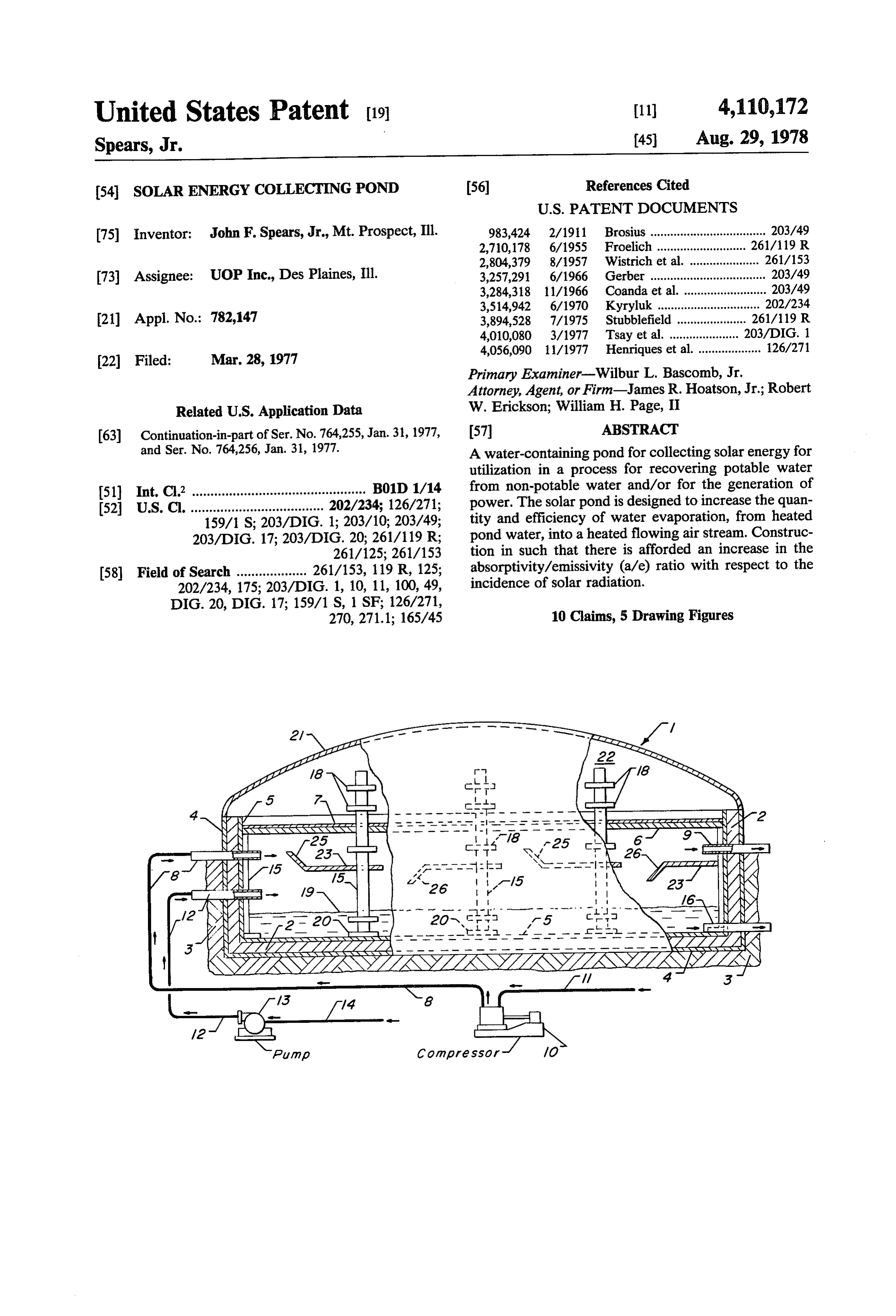
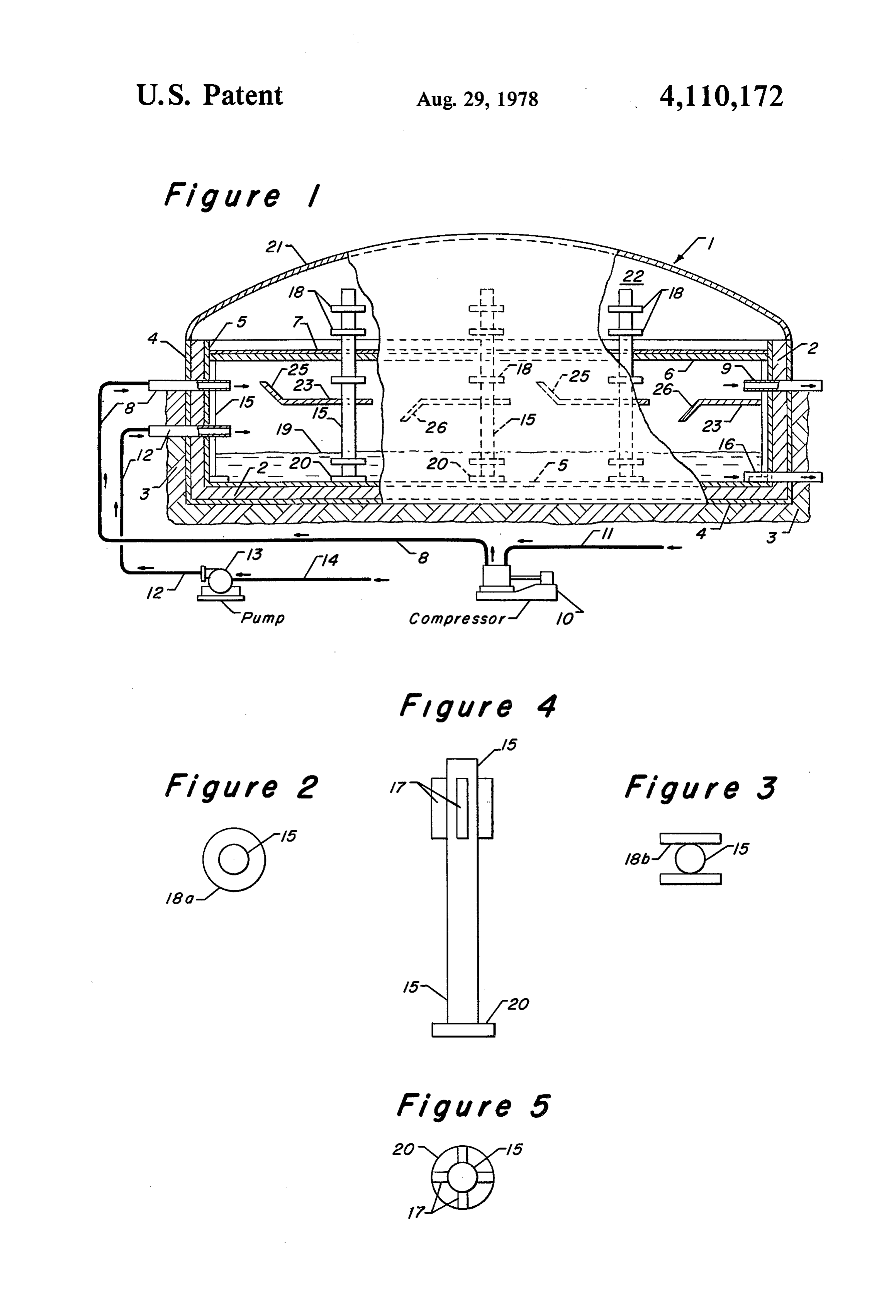
approximately 10 daylight hours. Solar pond efficiency The horizontal plate is coated along its entire upper is determined by comparing its absorptivity with the surface with a spectrally-selective material which fos total insolation available. In accordance with the pres ters the absorption of sunlight while reducing the emis ent invention, the solar pond is designed and con- 15 sion of infra-red radiation; this results in the attainment structed to maximize the efficiency with respect to the of a higher equilibrium temperature. One method of available insolation and also to increase the a/e (absorp producing the solar selective coating has been to coat tivity/emissivity) ratio. the surface with black copper oxide through the oxida In order to increase the efficiency of the solar pond, tion of a copper surface, or via thermal decomposition evaporative heat loss therefrom is inhibited through the 20 of copper nitrate. Another spectrally selective coating use of a covering. Suitable coverings are those which is black nickel formed by electro-deposition, or black are transparent to solar radiation, while simultaneously chrome which has been electroplated thereon. being opaque to long wave radiation. Obviously, since One particularly suitable solar pond is illustrated (in the technique employed herein requires a flowing air elevation) in the accompanying drawing; as shown, the stream, a covering is necessary to provide an enclosed 25 flowing air stream is introduced into an area above that system. Additionally, a suitable covering will provide into which the salinous water is charged. As shown, the an insulating effect between the air stream and water horizontal plate is intermediate the transparent dome being heated, and the atmosphere, such that conductive and the air inlet and outlet conduits. The horizontal and convective heat loss is minimized. A relatively thin plate is supported by a plurality of vertical standards (four to about six mils) sheet of polyvinyl chloride can 30 having a plurality of horizontal fins. The area below the be suitably employed, as can two such sheets which are horizontal plate is divided by means of a series of sepa uniformly tacked to provide a multitude of dead air rated baffles having alternating downwardly-angled bubbles having a minimum air gap of about one inch. and upwardly-angled edges. These baffles provide a The plastic sheet can be used in combination with an serpentine-like path for the heated air stream. underlayer of acrylic, fiberglass, polyvinyl carbonate, 35 in additionally describing my invention, reference or other plastic which is opaque to long wave radiation, will be made to the accompanying drawing which illus and which is formed into a modified sine wave having trates the several embodiments. It is understood that the angles of about 45° to about 75°. Other suitable cover drawing is not to scale, and is presented only for clarifi ings include glass wool which is reinforced with plastic, cation; there is no intent to impose an undue limitation opaque to long wave radiation, in combination with a 40 upon the scope and spirit of the invention as defined in tacked polyvinyl chloride sheet; a mat of fused polyvi the appended claims by presentation of the drawing. nyl chloride bubbles, about one to two inches; and, a BRIEF DESCRIPTION OF DRAWING combination of polyvinyl chloride-coated fiberglass to which the polyvinyl sheet is uniformly tacked. FIG. 1 is a partially-sectioned elevation of a solar Also of importance, with respect to the efficiency of 45 energy collecting pond generally indicated as . As the solar pond, is the insulation of the sides and bottom shown, the pond is partially below the grade level of thereof. Several techniques to accomplish this will be soil or sand 3.
come evident to those possessing the requisite skill in FIGS. 2 and 3 are plan views of vertical support the appropriate art. A variety of commercially-available standards 15, being presented to show alternative con insulating material can be used, including fiberglass, 50 figurations of the horizontal fins adapted thereto. styrofoam, vermiculite, matted or fused alimina fibers, FIG. 4 illustrates, in elevation, a vertical support etc. This is placed as a layer along the bottom surface standard having a plurality of vertical fins 47. and vertical sides of the pond which is generally formed FIG. 5 constitutes the plan view thereof. as a depression in the soil or sand. The insulating layer is lined (preferably on both sides) with a water- 55 DETALED DESCRIPTION OF DRAWING impermeable substance such as a thin, black sheet of With specific reference now to the drawing, the solar polymeric material including polyethylene, polyvinyl pond 1 is shown in a partially-sectioned elevation view chloride, polyvinyl carbonate, etc. Insulating material in FIG. 1. The pond is formed in a depression in soil 3 can be formed on and thus become integral with the by insulation layer 2 which is lined on both outer and water-impermeable polymeric sheet. 60 inner surfaces f4 and 5 with a water-impermeable sub The covered and well-insulated solar pond fosters the stance. A horizontal plate 6, having its upper surface evaporation of water vapor from the salinous water at coated with a spectrally selective black-bodied material the bottom of the pond, and saturation therewith of the 7, is disposed proximate to the upper peripheral edges of heated air stream flowing over the sainous water. As insulation layer 2 and forms a dead air space 22 below used herein, and in my copending applications, the term 65 transparent dome 2.
“saturation' is not necessarily intended to connote The solar pond it is adapted with an air inlet conduit 100% saturated air. Rather, it refers to a more practi 8 and an air outlet conduit 9 disposed below horizontal cally obtained level of about 95%, or more, of the possi piate 6 and above the level of pond water 39. Conduit 8
Page 6
discharges air from compressive means 10 which re ply means and, (iv) at least one air outlet conduit, ceives ambient or recycled air through suction line 11. said air conduits being disposed above said water A salinous water inlet conduit 12 communicates with conduits;
the interior of solar pond 1 and water-supplying means (b) a layer of insulating material contacting the inte 13 which is connected to the water source by way of 5 rior surface of the bottom and vertical walls of said suction line 14. Water is removed from the pond reservoir;
through outlet conduit 16. Although the air and water (c) a horizontal plate disposed above said air and conduits are shown singularly, the size of the solar pond water conduits, and having (i) substantially the dictates a plurality of each. same area as said reservoir and, (ii) a coating of Horizontal plate 6 is supported by a plurality of verti- 10 spectrally-selective material contiguous with the cal standards 14 which terminate in a flanged portion 20 upper surface thereof;
which rests on the bottom surface of the solar pond. In (d) a plurality of spaced-apart vertical support stan a preferred configuration, standards 15 extend up dards attached to said horizontal plate and in wardly through horizontal plate 6 into dead air space contact with the bottom of said reservoir; and, 22. Internal vertical standards are adapted with a plural- 15 (e) a transparent cover attached to the upper periph ity offins 18; these may be horizontal as shown in FIG. eral edges of said reservoir, and forming a dead air 1, or vertical as hereinafter described. At least one such space above said horizontal plate. fin 18 is along that portion of vertical support standard 2. The solar pond of claim 1 further characterized in 15 which extends into dead air space 22; likewise, at that said horizontal plate is imperforate. least one fin is below the surface of pond water 19 and 20 3. The solar pond of claim 1 further characterized in one within the area through which the air stream is that said layer of insulating material is linked on one flowing.
Also supported by vertical standards 15 is a plurality surface thereof with a water-impermeable substance. of separated horizontal baffles 23 having alternating that bothsolar 4. The pond of claim 1 further characterized in upwardly-angled edges 25 and downwardly-angled 25 material are linedand inner with outer surfaces of said insulating a water-impermeable substance.
edges 26. These provide a serpentine-like air flow over 5. The solar pond of claim 1 further characterized in the pond water 19 and enhance the pick-up of evapo that said support standards extend upwardly through rated water. said horizontal plate into said dead air space. Variations offins 18 are illustrated in the plan views of FIGS. 2 and 3, being substantially circular (18a) and 30 that6. said
The solar pond of claim 1 further characterized in vertical support standards contain at least one as a pair of 180°-opposite "I'bars' (18b), respectively. fin.
FIG. 4 in elevation, and FIG. 5, in plan view, illus 7. The solar pond of claim 6 further characterized in trate still another fin variation in the form of four verti cal flared portions 17. that said vertical support standards contain at least one The foregoing specification, when viewed in con- 35 horizontal fin.
junction with the accompanying drawing, is believed to that8. said The solar pond of claim 6 further characterized in support standards contain a plurality of fins.
present a clear understanding and a concise description 9. The solar pond of claim 8 further characterized in of the solar energy collecting pond encompassed by the present invention. that (i) at least one of said fins is disposed within said I claim as my invention: 40 dead air space, (ii) at least one is disposed below said 1. A solar energy collecing pond which comprises, in horizontal plate and, (iii) at least one is disposed below cooperative combination: the surface of water contained in said pond. (a) a water-containing reservoir having bottom and 10. The solar pond of claim 1 further characterized in vertical walls with an interior surface and said that a plurality of separated horizontal baffles having reservoir further having (i) at least one water inlet 45 alternating downwardly-angled and upwardly-angled conduit communicating with water supply means, edges is disposed intermediate said air inlet conduit and (ii) at least one water outlet conduit, (iii) at least the surface of the waterk contained
in said pond.
one air inlet conduit communicating with air sup
Provenance
- Collection
- Cited prior art
- Original PDF
- patentimages.storage.googleapis.com →
- Filed
- 1977-03-28
- Pages
- 6
- Method
- pdftotext (the PDF's own text layer) + pdftoppm 300dpi page scans
- Source
- Google Patents bibliographic record
- Granted
- 1978-08-29
- Inventors
- John F. Spears, Jr.; UOP LLC
- Transcribed from
- patentimages.storage.googleapis.com →