patent · US3923039
Solar energy heating system
2 December 1975
Page 1 — bibliographic record
United
Fabel
States Patent (19) 11 3,923,039
54). SOLAR ENERGY HEATING SYSTEM
76) Inventor: Gerald Fallbel, 472 Westover Road, (57) ABSTRACT Stamford, Conn. 06902
A focused solar heating system is provided having a 22 Filed: Feb. 7, 1975 focusing reflector which is generally scoop-shaped. A 21 Appl. No.: 547,917 solar collector plate is mounted on the front of the fo cusing reflector to directly accept direct solar radia tion and diffuse radiation which strikes the front sur 52 U.S. Cl.................................. 126/271; 126/270 face of the plate. The remainder of the entrance aper (5ll Int. Cl.’............................................. F24J 3/02 ture of the focusing reflector accepts both on- and off 58 Field of Search ............ 126/270, 271; 237/1 A; axis solar direct and diffuse radiation which is re 62/2; 350/288, 293, 294 flected by the focusing reflector and applied to the
rear surface of the solar collector plate. The focusing reflector has a concave reflective surface made up of
UNITED STATES PATENTS first and second merging curves which are optimized 3,179, 105 4/1965 Fallbel................................. 26/271 so that the front and rear surfaces of the solar collec 3,262,493 7/1966 Hervey................................ 126/27 | tor plate accept the larger solid angle of both direct 3,841,302 10/1974 Fallbel................................. 126/271 and diffuse rays from the sun and provides an optical 3,884,217 5/1975 Wartes................................ 126/270 gain which increases the efficiency of the system. The FOREIGN PATENTS OR APPLICATIONS solar collection system may be incorporated in a verti 1,243,221 4/1960 France................................ 126/27 cal wall of a building and made partially transmissive, 1,287,760 2/1962 France................................ 126/270 or may be incorporated in a separate structure for supplementing the heating or cooling of a building or
Primary Examiner-Kenneth W. Sprague providing hot water therefor. Assistant Examiner-James C. Yeung 10 Claims, 3 Drawing Figures Attorney, Agent, or Firm-Joseph Levinson, Esq.
Page 2
Drawing sheet — no readable text.

Page 3
Drawing sheet — no readable text.
Page 4
flective surface is a continuous, substantially curved
SOLAR ENERGY HEATING SYSTEM surface of first and second merging curves formed, for example, by first and second radii of curvature, the first
BACKGROUND OF THE INVENTION radius being substantially equal to the height of the solar collector plate and projecting from the uppermost
This invention relates to a solar energy system, and point on the solar collector plate to form the first curve, more particularly to focusing solar collectors which op having a cylindrical shape behind the solar collector timize the collection of solar radiation, both direct and plate. The second radius in this example is greater than diffuse, and provide an optical gain for the collection of the first radius, and projects from a point in front of and such energy. O below the uppermost point of the first radius to form Solar energy has been proposed for the heating and the second curve behind the entrance aperture, such for cooling of structures, but because of readily avail that solar radiation entering the entrance aperture is able and cheap forms of other energy, such as coal, oil effectively applied to the under side of the solar collec and gas, such applications have been limited mainly for tor plate.
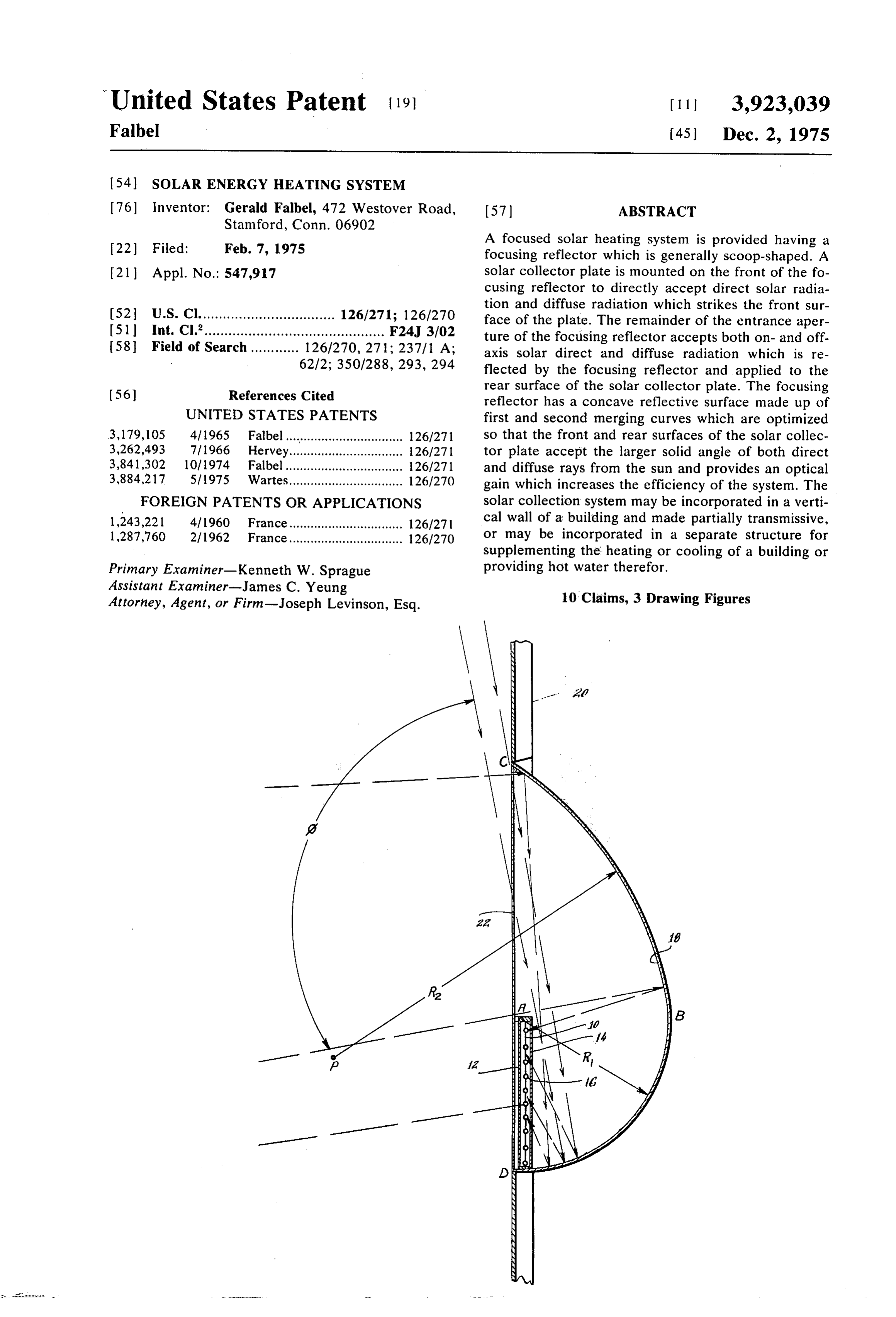
economic reasons. With the advent of energy shortages 15 it has now become essential to tap this huge, readily BRIEF DESCRIPTION OF THE DRAWINGS available energy source. Many of the solar energy sys FIG. 1 is a side elevation in section of an embodiment tems which have been proposed for converting the of the focusing solar energy collector system which is sun's energy into heat, generally require rather large diagrammatic for explanatory purposes, and is also il collectors or reflectors which are unsightly, uneconom 20 lustrated as being incorporated in a vertical wall of a ical, difficult to utilize or employ in building construc building, which constitutes one embodiment of the tion, and/or continually exposed to the elements, which present invention.
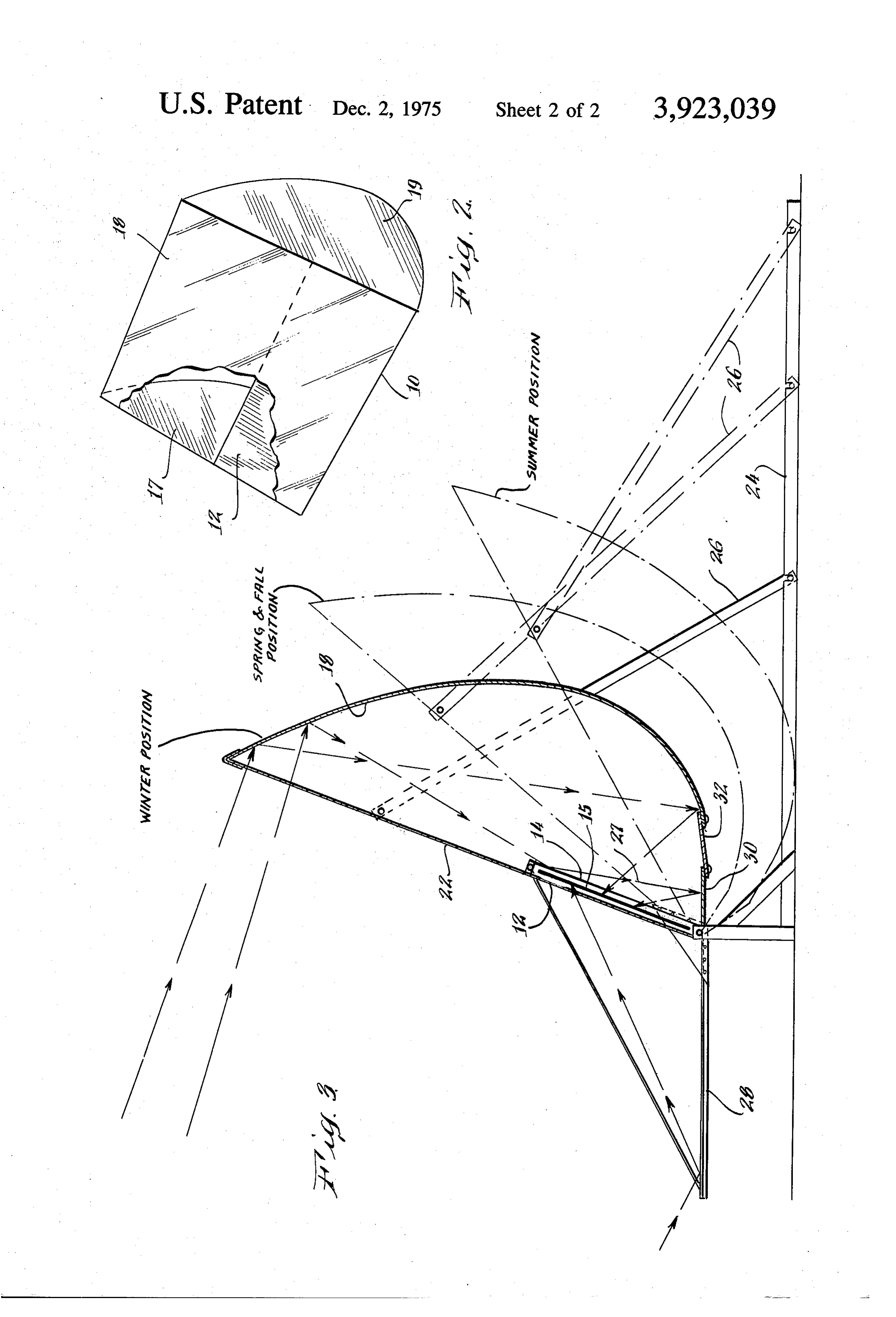
limit their usefulness, or degrade their use within a per FIG. 2 is an isometric view of the solar collector illus iod of time. Many of the focusing solar collectors of trated in FIG. 1 which illustrates its general configura various kinds suffer the disadvantage of not collecting 25 tion.
adequate amounts of the sun's diffuse radiance result FIG. 3 is a side elevational view, partly in section, of ing from aerosol particles scattering, for example, blue another embodiment of the focusing solar energy Sys sky, haze, clouds, etc. which, in areas which have sig tem embodied in this invention.
nificant haze, smoke and humidity, represents a signifi cant amount of uncollected solar energy. The solar col DESCRIPTION OF THE PREFERRED lectors were also not suitable for mounting in vertical EMBODIMENTS walls of buildings for one reason or another, nor were Referring now to FIG. 1, the focusing solar energy the collecting systems versatile or efficient enough to collection system of this invention includes a solar col be utilized separately from existing structures in order lector plate 10 having a front, short wavelength-trans to supplement the heating of the building or to provide 35 parent surface 12 and a similar rear transparent surface hot water therefor.
14 with a grid of pipes 16 therebetween. The pipes 16
OBJECTS AND SUMMARY OF THE INVENTION carry a liquid medium which is circulated through the Accordingly, it is an object of the present invention pipes to the and is heated or cooled by the radiation applied collector plate 10. The liquid is circulated by to provide a new and improved focusing solar energy 40 conventional circulating pumps (not shown) and uti system which collects direct and diffuse radiation with lized by conventional means to heat the building or the same or better efficiency than a flat plate collector, supply hot water therefor, or to cool it by radiation to while providing an optical gain therefor. the cold night sky. Since this structure does not consti A further object of this invention is to provide a new tute a part of the present invention, no description and improved focusing solar collector which provides thereof is herein provided.
improved solar collection efficiency, and allows the use The liquid medium which is circulated in the pipes 16 of smaller collector plates. may be of any suitable type, such as water, oil, or air. If Another object of this invention is to provide a new required, the liquid medium may include suitable anti and improved solar collector which is suitable for in freeze additives to resist freezing if this is a problem. corporation in the vertical sidewall of a building. 50 Furthermore, additives may be added for blackening Still another object of this invention is to provide a the absorbing fluid to enhance the absorption of solar new and improved focusing solar collector system energy applied thereto. In another configuration which which may be used separately from an existing struc is illustrated in FIGS. 3, the collector plate 10 may be ture to supplement the heating and/or cooling of a made up of transparent tubing in which a black absorb building. 55 ing liquid flows, or liquid may flow between two trans
A further object of this invention is to provide an im parent plates of glass or plastic 12 anad 14 which have proved focusing solar collection system which may be their perimeter sealed. The collector plate 10 may also manually or automatically moved to optimize solar col be covered with a selective black surface which absorbs lection as a function of season. heavily in the short wavelength region between 0.4 and In carrying out this invention in one illustrative em 60 2 micrometers and has a low emittance in the 2 to 20 bodiment thereof, a focused solar heating system is micrometer spectral region. In all of these collector provided having a focusing reflector with an entrance plate configurations, the collector plate 10 absorbs ra aperture and a concave reflecting surface positioned diation applied on or through both its front and rear behind the entrance aperture. A solar collector plate is surfaces 12 and 14 as compared with a normal flat col mounted relative to the focusing reflector in the plane 65 lector plate which absorbs radiation only on its front of the entrance aperture, and substantially covers the surface.
lower portion of the entrance aperture when the focus Referring now to FIG. 2, the solar energy system em ing reflector is a vertical orientation. The concave re bodied in the present invention includes a concave re
Page 5
flective surface 18 bounded by reflecting side walls 17 and window transmission is approximately 3 to l as and 19. The concave reflective surface 18 may be of compared to a single flat collector having a vertical di any suitable material such as polished aluminum, a suit mension of C-D. This results in desirably higher collec able plastic having a reflective costing thereon, or any tor plate temperatures.
other type of suitable mirrored surface which collects It should be emphasized that a single radius R2 cen and reflects the solar energy applied thereto to the tered at point P represents only the simplest implemen back surface 14 of the solar collector plate 10. In a ver tation of the invention. Further optimization using par tical orientation as shown, the solar collector plate 10 is abolic, hyperbolic, or similar curved functions for the located and covers the lower portion of the focusing re reflective surface B-C is possible, thereby further in flector 18 and is positioned substantially in the plane of O creasing the value of reflecting entrance aperture A–C the entrance aperture of the focusing reflector 18. The times d solid angle combination. As is shown in FIG. 1, focusing reflector 18 along with its sidewalls 17 and 19, the solar collecting system of this invention is incorpo and the solar collector plate 10 mounted thereon, have rated in the vertical sidewall 20 of a building. In this a general scoop-shape configuration. configuration, the entrance aperture C-D is vertical, in Referring again to FIG. 1, the concave reflective sur 15 which the ratio of the reflecting entrance aperture A-C face 18 which is also referred to as the focusing reflec over the direct entrance aperture tor 18 has an entrance aperture C-D, covered in part by the solar collector plate 10 from points A to D, ( A-D
which forms the direct entrance aperture where solar energy, both direct and diffuse, is applied directly to 20
the front surface 2 of the solar collector 10. The re maining portion of the entrance aperture C-D com can be made larger than 2:1 at the expense of an allow prises the reflective entrance aperture A-C. The focus ably the smaller value of solid angle ds, thereby increasing energy intensity gain as compared to a singlesided ing reflector or concave reflective surface 18 is made up of two curvatures B-C and B-D which are joined at 25 vertical flat plate collector even further. point B, with point Blocated by passing a plane perpen Conversely, if it is desirable to increase the elevation dicular to the entrance aperture C-D at point A and in angle b, and/or azimuth angle, if the cylindrical axis of tersecting surface 18 at B. In its simplest configuration, the focusing reflector 18 is rotated, the ratio of the re the reflective surface 18 has a substantially cylindrical flective entrance aperture A-C to the direct entrance curvature from B to D, having a radius R projecting 30 aperture A-D can be made smaller, resulting in a com from point A which is equal to the collector plate mensurate increase in the solid angle b. height A-D, with A-B being equal to A-D and perpen In the configuration shown in FIG. 1 where the solar dicular thereto. Curvature B-C is so constructed that energy system of the present invention is embodied in a all rays entering aperture A-C making an angle ds are vertical sidewall of a building, the reflecting surface either reflected by curve B-C or passed directly 35 B-C can be made partially transparent. In this way, oc through the aperture A-B and are thus applied to the cupants of the building can look out, and sunlight can back surface 14 of the solar collector plate 10. Curve some in through the window formed by the reflecting B-C is optimized so that the vertical ray angle b is max entrance aperture A-C, thus allowing the solar collec imized concurrently with the dimension A-C, thereby tor to form part of a usable sidewall which significantly maximizing the elevation angle entrance product of 40 increases the area providing solar energy collection rays passing through A-C which also pass through A-B. without reducing substantially the window area of the Once having passed through A-B the rays may or may building. This also provides desirable solar shading or not be reflected by the curve B-D, but they all finally reflective glass, thereby reducing solar heat loads for reach the rear surface 14 of the collector plate 10 and 45 the building air conditioning in the summer. In this con accordingly are absorbed thereby. figuration the amount of solar energy collected by the The simplest construction of curve B-C is obtained solar collector plate 10 is reduced only a relatively by centering a radius R2 of approximately 3R at a point small amount, because it is characteristic of partially P in the zone in front of and below the normal to direct transparent aluminized coatings that they transmit well, entrance aperture A-D at point A. This arrangement e.g. 10-20 percent in the 0.4 to 0.5 micrometers blue results in a dimension A-C being 2 times A-D and a 50 green visible region of the spectrum, while the reflec value of db equal to approximately 95 to 100. Since tivity of such a coating rapidly increases at longer the flat ends 17 and 19 of the focusing reflector 18 are wavelengths, i.e. 0.6 to 2.0 micrometers where most of parallel and reflective, a solid angle ray bundle having the solar heat energy is located in the spectrum. dimensions of 100 in elevation by 180° in azimuth The entire entrance aperture C-D is preferably cov passes through the reflective entrance aperture A-C, 55 ered with a transparent material such as a glass plate or ultimately reaching the rear surface 14 of the collector transparent plastic 22 which would protect both the plate 10. This solid angle represents 100 percent of the collector plate 10 and the reflecting surface 18 from solid angle of diffuse sky radiation that could have been the elements. Otherwise a build-up of moisture in the collected by a normal flat collector plate whose front form of rain, snow, or other precipitation, or a buildup surface makes an angle of 100 with the horizontal. 60 of dust, soot, or other environmental deposits would However, since the reflecting entrance aperture A-C is seriously hamper the proper functioning of the solar 2 times the direct entrance aperture A-D, this diffuse collection system.
energy as well as the direct solar energy is increased in Referring now to FIG. 3, where the same elements intensity per unit collector area by a factor of approxi are provided with the same reference numerals as in mately 2. Furthermore, since the front surface 12 of the 65 the previous figures, solar energy collection system collector plate 10 also absorbs direct and diffuse solar may be mounted on a frame 24 which may be either in irradiance, the over-all gross energy gain per unit area corporated in an existing structure or utilized sepa of the collector plate, assuming 100 percent reflection rately therefrom. As shown in FIG. 3, an arm 26 is at
Page 6
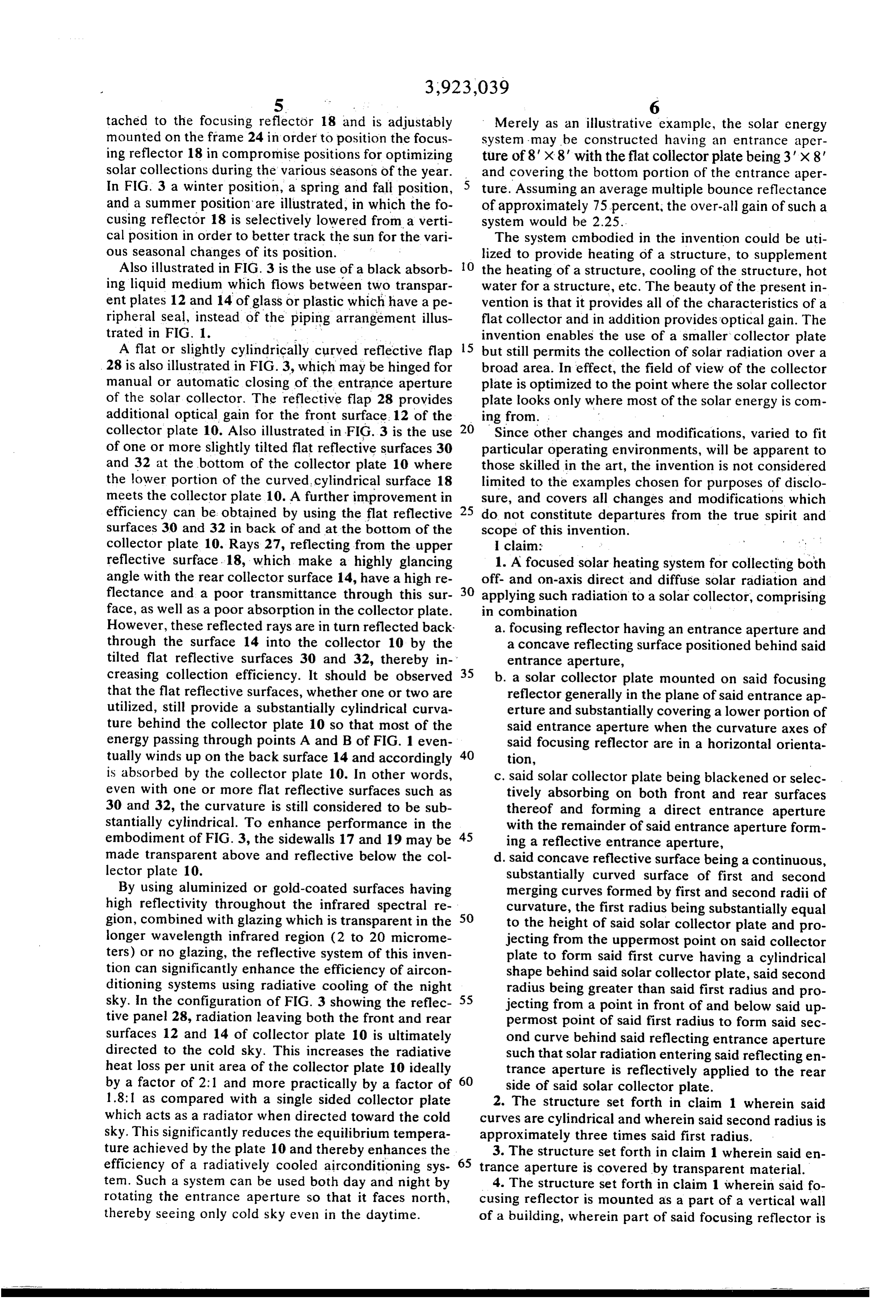
tached to the focusing reflector 18 and is adjustably Merely as an illustrative example, the solar energy mounted on the frame 24 in order to position the focus system may be constructed having an entrance aper ing reflector 18 in compromise positions for optimizing ture of 8" x 8" with the flat collector plate being 3' x 8" solar collections during the various seasons of the year. and covering the bottom portion of the entrance aper In FIG. 3 a winter position, a spring and fall position, 5 ture. Assuming an average multiple bounce reflectance and a summer position are illustrated, in which the fo of approximately 75 percent, the over-all gain of such a cusing reflector 18 is selectively lowered from a verti system would be 2.25.
cal position in order to better track the sun for the vari The system embodied in the invention could be uti ous seasonal changes of its position. lized to provide heating of a structure, to supplement Also illustrated in FIG. 3 is the use of a black absorb 10 the heating of a structure, cooling of the structure, hot ing liquid medium which flows between two transpar water for a structure, etc. The beauty of the present in ent plates 12 and 14 of glass or plastic which have ape vention is that it provides all of the characteristics of a ripheral seal, instead of the piping arrangement illus flat collector and in addition provides optical gain. The trated in FIG. 1. invention enables the use of a smaller collector plate A flat or slightly cylindrically curved reflective flap 15 but still permits the collection of solar radiation over a 28 is also illustrated in FIG. 3, which may be hinged for broad area. In effect, the field of view of the collector manual or automatic closing of the entrance aperture plate is optimized to the point where the solar collector of the solar collector. The reflective flap 28 provides plate looks only where most of the solar energy is com additional optical gain for the front surface. 12 of the ing from. .
collector plate 10. Also illustrated in FIG. 3 is the use 20 Since other changes and modifications, varied to fit of one or more slightly tilted flat reflective surfaces 30 particular operating environments, will be apparent to and 32 at the bottom of the collector plate 10 where those skilled in the art, the invention is not considered the lower portion of the curved, cylindrical surface 18 limited to the examples chosen for purposes of disclo meets the collector plate 10. A further improvement in sure, and covers all changes and modifications which efficiency can be obtained by using the flat reflective 25 do not constitute departures from the true spirit and surfaces 30 and 32 in back of and at the bottom of the scope of this invention.
collector plate 10. Rays 27, reflecting from the upper | claim: . reflective surface. 18, which make a highly glancing 1. A focused solar heating system for collecting both angle with the rear collector surface 14, have a high re off- and on-axis direct and diffuse solar radiation and flectance and a poor transmittance through this sur 30 applying such radiation to a solar collector, comprising face, as well as a poor absorption in the collector plate. in combination
However, these reflected rays are in turn reflected back a. focusing reflector having an entrance aperture and through the surface 14 into the collector 10 by the a concave reflecting surface positioned behind said tilted flat reflective surfaces 30 and 32, thereby in entrance aperture, creasing collection efficiency. It should be observed 35 b. a solar collector plate mounted on said focusing that the flat reflective surfaces, whether one or two are reflector generally in the plane of said entrance ap utilized, still provide a substantially cylindrical curva erture and substantially covering a lower portion of ture behind the collector plate 10 so that most of the said entrance aperture when the curvature axes of energy passing through points A and B of FIG. 1 even said focusing reflector are in a horizontal orienta tually winds up on the back surface 14 and accordingly 40 tion, is absorbed by the collector plate 10. In other words, c. said solar collector plate being blackened or selec even with one or more flat reflective surfaces such as tively absorbing on both front and rear surfaces 30 and 32, the curvature is still considered to be sub thereof and forming a direct entrance aperture stantially cylindrical. To enhance performance in the with the remainder of said entrance aperture form embodiment of FIG. 3, the sidewalls 17 and 19 may be 45 ing a reflective entrance aperture, made transparent above and reflective below the col d. said concave reflective surface being a continuous, lector plate 10. substantially curved surface of first and second By using aluminized or gold-coated surfaces having merging curves formed by first and second radii of high reflectivity throughout the infrared spectral re curvature, the first radius being substantially equal gion, combined with glazing which is transparent in the 50 to the height of said solar collector plate and pro longer wavelength infrared region (2 to 20 microme jecting from the uppermost point on said collector ters) or no glazing, the reflective system of this inven plate to form said first curve having a cylindrical tion can significantly enhance the efficiency of aircon shape behind said solar collector plate, said second ditioning systems using radiative cooling of the night 55 radius being greater than said first radius and pro sky. In the configuration of FIG. 3 showing the reflec jecting from a point in front of and below said up tive panel 28, radiation leaving both the front and rear permost point of said first radius to form said sec surfaces 12 and 14 of collector plate 10 is ultimately ond curve behind said reflecting entrance aperture directed to the cold sky. This increases the radiative such that solar radiation entering said reflecting en heat loss per unit area of the collector plate 10 ideally trance aperture is reflectively applied to the rear by a factor of 2:1 and more practically by a factor of 60 side of said solar collector plate. 1.8:1 as compared with a single sided collector plate 2. The structure set forth in claim 1 wherein said which acts as a radiator when directed toward the cold curves are cylindrical and wherein said second radius is sky. This significantly reduces the equilibrium tempera approximately three times said first radius. ture achieved by the plate 10 and thereby enhances the 3. The structure set forth in claim 1 wherein said en efficiency of a radiatively cooled airconditioning sys 6 trance aperture is covered by transparent material. tem. Such a system can be used both day and night by 4. The structure set forth in claim 1 wherein said fo rotating the entrance aperture so that it faces north, cusing reflector is mounted as a part of a vertical wall thereby seeing only cold sky even in the daytime. of a building, wherein part of said focusing reflector is
Page 7
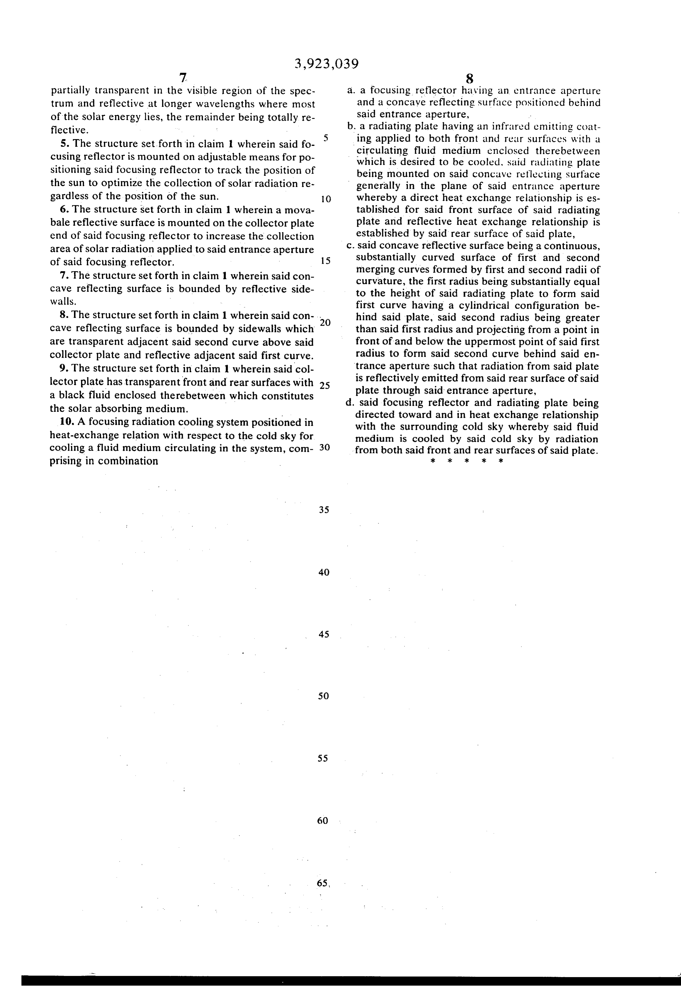
partially transparent in the visible region of the spec a. a focusing reflector having an entrance aperture trum and reflective at longer wavelengths where most and a concave reflecting surface positioned behind of the solar energy lies, the remainder being totally re said entrance aperture, .. flective. b. a radiating plate having an infrared emitting coat 5. The structure set forth in claim 1 wherein said fo 5 ing applied to both front and rear surfaces with a cusing reflector is mounted on adjustable means for po circulating fluid medium enclosed therebetween sitioning said focusing reflector to track the position of which is desired to be cooled, said radiating plate being mounted on said concave reflecting surface the sun to optimize the collection of solar radiation re generally in the plane of said entrance aperture gardless of the position of the sun. O whereby a direct heat exchange relationship is es 6. The structure set forth in claim 1 wherein a mova tablished for said front surface of said radiating bale reflective surface is mounted on the collector plate plate and reflective heat exchange relationship is end of said focusing reflector to increase the collection established by said rear surface of said plate, area of solar radiation applied to said entrance aperture . . said concave reflective surface being a continuous, of said focusing reflector. 15 substantially curved surface of first and second 7. The structure set forth in claim 1 wherein said con merging curves formed by first and second radii of curvature, the first radius being substantially equal cave reflecting surface is bounded by reflective side to the height of said radiating plate to form said walls. first curve having a cylindrical configuration be 8. The structure set forth in claim 1 wherein said con- , hind said plate, said second radius being greater
cave reflecting surface is bounded by sidewalls which than said first radius and projecting from a point in are transparent adjacent said second curve above said front of and below the uppermost point of said first collector plate and reflective adjacent said first curve. radius to form said second curve behind said en 9. The structure set forth in claim 1 wherein said col trance aperture such that radiation from said plate lector plate has transparent front and rear surfaces with 25 is reflectively emitted from said rear surface of said a black fluid enclosed therebetween which constitutes plate through said entrance aperture, the solar absorbing medium. d. said focusing reflector and radiating plate being 10. A focusing radiation cooling system positioned in directed toward and in heat exchange relationship with the surrounding cold sky whereby said fluid heat-exchange relation with respect to the cold sky for medium is cooled by said cold sky by radiation cooling a fluid medium circulating in the system, com 30 from both said front andsk rear surfaces of said plate. prising in combination sk xk x 2k
Provenance
- Collection
- Cited prior art
- Original PDF
- patentimages.storage.googleapis.com →
- Filed
- 1975-02-07
- Pages
- 7
- Method
- pdftotext (the PDF's own text layer) + pdftoppm 300dpi page scans
- Source
- Google Patents bibliographic record
- Granted
- 1975-12-02
- Inventors
- Gerald Falbel
- Transcribed from
- patentimages.storage.googleapis.com →