patent · US2793509
Method of and apparatus for cooling inhabitable and other enclosures
28 May 1957
Page 1 — bibliographic record
May 28, 1957 W. E. KEEN 2,793,509
METHOD OF AND APPARATUS FOR COOLING
INHABITABLE AND OTHER ENCLOSURES
Filed Oct. 4, 1955 2 Sheets-Sheet l
SSS
SSSn SS
sSs
rareawaazac
Aryers as
SSSC
INVENTOR
VICTOR I. KEEN
Page 2
May 28, 1957 W. E. KEEN 2,793,509
METHOD OF AND APPARATUS FOR COOLING
INHABITABLE AND OTHERENCLOSURES
Filed Oct. 4, 1955 2 Sheets-Sheet 2
NS its as
SSXX
Aless:
2ZZZZZZZZZSINet I:22ZZZZZ1 INVENTOR
Page 3
United States Patent Office Patented Miay 28, 1957
expelling the vaporized moisture. In the former instance the procedure is a messy one, requiring as it does frequent cleaning of the fluid conduits. Furthermore, particularly 2,793,509 in apartment installations, a suitable drainage region is METHOD OF AND APPARATUS FOR COOLING 'not available. In the latter instance the heat required NHABITABLE AND OTHERENCLOSURES to effect the evaporation further increases the cost of operation of the apparatus as well as lowering the
Victor . Keen, Evanston, i. efficiency of the same.
Application October 14, 1955, Serial No. 540,389 The present invention is designed to overcome the O above noted limitations that are attendant upon the use 6 Claims. (CI. 62-139) of so-called present day air conditioning apparatus and toward this end it contemplates the provision of a novel form of cooling and dehumidifying apparatus which does not depend for its effectiveness upon the mechanical
The present invention relates to an improved method S treatment of either the air itself, or a fluid coolant but of and an apparatus for cooling and dehumidifying en which rather depends upon a principle of operation closures, particularly inhabitable enclosures as, for ex wherein heat is extracted from the air undergoing cooling ample, residential and office buildings, animal, shelters and dehumidification by the principle known as surface such as barns and the like, and other enclosures where the evaporation with the evaporation taking place in an comfort of human or animal life is to be considered. 20. artificially prepared evaporation bed situated outside of The invention is however capable of a wide variety of the enclosure undergoing treatment and with the air being other uses and the same may, if desired, be employed, drawn through the bed in heat exchange relationship with with suitable modification, for use in the cooling and respect thereto. In one form of the invention, particularly dehumidifying of other types of enclosures such as ware where residential installations are concerned, the arti houses and other storage spaces, garages and other forms 25 ficially prepared evaporation bed is in the form of an of commercial establishments too numerous to mention. installation beneath the surface of the earth preferably Irrespective however of the particular use to which the at a region in close proximity to the dwelling or other present invention may be put, the essential features of enclosure undergoing treatment and, in another modified the same are always preserved. form thereof, useful particularly in connection with Present day conventional air cooling and dehumidfy 30 apartment house and other instances where ground space ing apparatus, commonly referred to as air conditioning is not readily available, the evaporation bed is in the form apparatus, depends for its effectiveness upon either the of a roof installation, artificially constructed to simulate mechanical treatment of the air itself, or upon the me and have the effect of the ground installation. chanical treatment of a coolant fluid wherein alternate It is among the principal objects of the present in compression and expansion cycles are resorted to to bring 35,vention to provide an air cooling and dehumdification the coolant fluid to a low temperature, usually. Sub-zero apparatus of the character briefly outlined above which temperature, in accordance with well known physical is substantially entirely automatic in its operation and principies, and thereafter the low temperature coolant which, except for the provision of a single air circulating fluid and air are brought into heat exchange relationship 40 blower for impelling the cooled and dehumidified air and the thus cooled air is distributed throughout the through the system and conducting the same into the enclosure. enclosure, is possessed of no moving parts and which Air conditioning apparatus of the type briefly outlined therefore requires no automatic or manual controls for above is possessed of numerous limitations, principal its proper functioning.
among which is the cost of operation thereof, utilizing 45 Another important object of the invention is to pro as they invariably do one or more motor driven com vide an air conditioning apparatus suitable for domestic pressor units and one or more motor driven blower units, the system being essentially electrically powered and or industrial uses which when set into operation is auto matic in its function and which, without the use of operated. Various manual and automatic controls are thermostatic controls, will automatically adjust itself to provided for the proper operation of such equipment 50 the ambient temperature surrounding the enclosure under and the malfunctioning of these controls frequently leads going treatment, thus increasing its cooling effect when to high maintenance costs. Additionally, the capacity the demand for cool air increases and, conversely, decreas of such units, particularly the small household variety ing its cooling effect when such demand is no longer thereof, is relatively small and in the larger residential present.
homes and apartments several such units must be em 55 Another object of the invention is to provide an air ployed, usually one for each partitioned enclosure. Still conditioning apparatus of this sort having associated further, even where large capacity units are employed, therewith efficient means for filtering and purifying the when the ambient temperature reaches abnormal degrees air introduced into the enclosure both by a mechanical it has been found that because the thermostatic controls filtering operation and an automatic physical "settling for the compressor motor maintain the latter in sub 60 out operation wherein any objectionable ambient gases stantially constant operation overheating of the com or fumes are condensed and conducted from the system. pressor and at least temporary failure thereof takes Yet another object, in a system of this sort, is to pro place with this occurring at a time when the expected vide an air conditioning apparatus wherein substantially beneficial results of the system are most to be desired. all of the cooling and dehumidifying instrumentalities Yet another limitation that is attendant upon the use 65 employed in the system are arranged externally of the of such conventional air conditioning equipment, par enclosure undergoing treatment thereby rendering space ticularly those which make provision for dehumidifying that otherwise would be consumed for housing such the air as well as cooling the same, is that some disposi instrumentalities available for other purposes. tion must be made of the condensed moisture extracted Another object of the invention in a heating system from the air. In some installations this moisture is con 70 of the character described above, is to provide a novel ducted in liquid form to a point of discharge and in form of heat exchange unit adapted to be embedded with others provision is made for evaporating the same and in an artificial evaporation bed and which unit employs a
Page 4
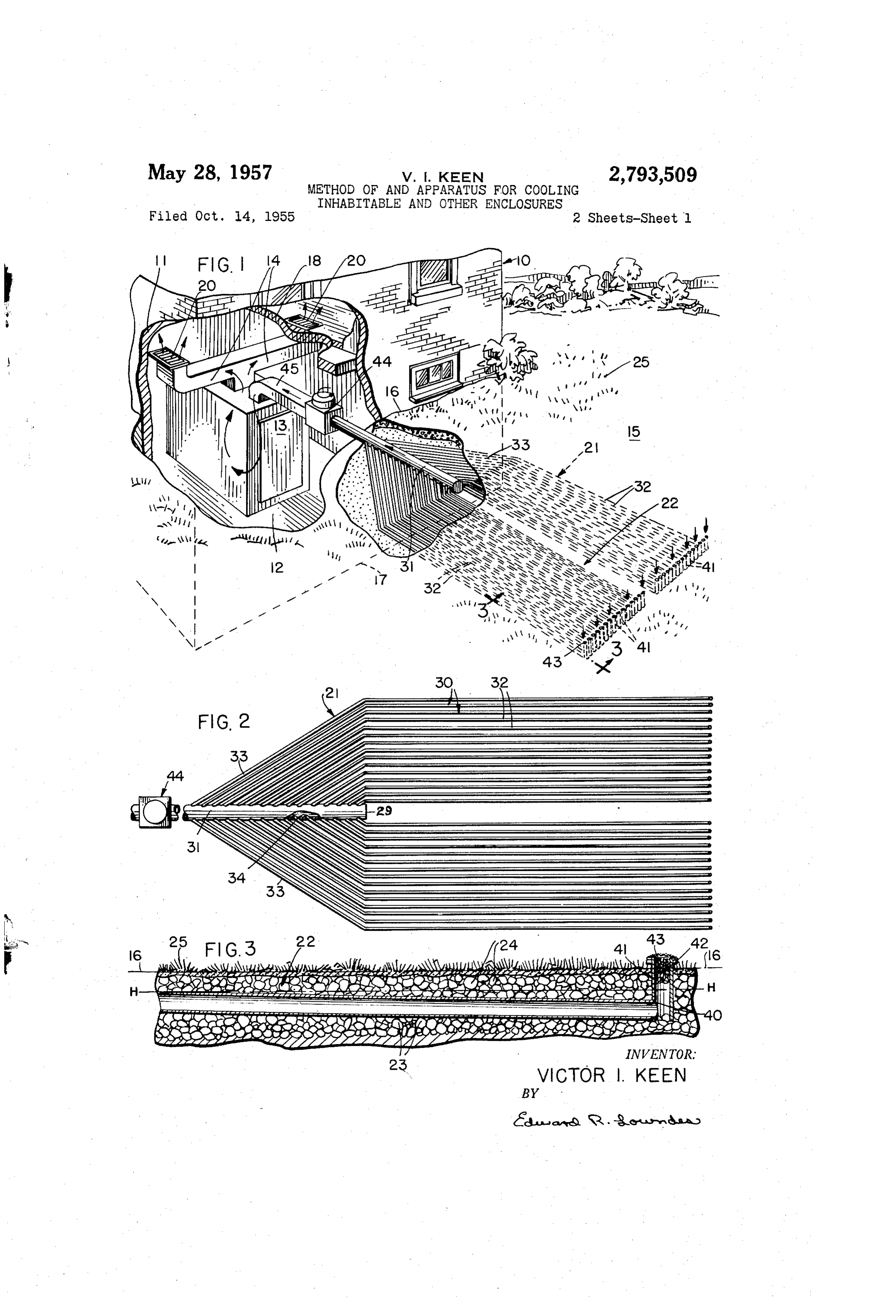
series of interconnected and communicating conduits but The form of air conditioning apparatus shown in Figs. in which the conduits are assembled upon one another 1 to 3 inclusive involves in its general organization a without the use of threaded or other fittings such as T heat exchange unit or assembly designated in its entirety or elbow-connections and the like. at 21, the latter being substantially completely disposed The provision of an air cooling and dehumidifying below the level 16 of the ground 15 and being dis apparatus which is extremely simple in its construction; posed within a prepared evaporation bed 22 (Fig. 3) ad one which employs a minimum number of moving parts jacent the building 10 and disposed wholly exteriorly of and which therefore is unlikely to get out of order; one the latter. The bed 22 may be prepared by excavating which is capable of easy installation; one which is rugged the soil to provide a shallow pit having an overall area - and durable and which therefore is possessed of a long 0. of a size and shape to accommodate the assembly 21 and useful life; one which requires little or no mainte and having a depth slightly greater than the vertical di nance operation or attention on the part of the occu mension of the heat exchange assembly. The excavation pants of the enclosure; one which requires for its oper is then partially filled with a layer 23 of loose gravel ation no coolant fluid or other chemical preparations; one of relatively small size, commercial path gravel being which is silent and efficient in its operation; one which 5 suitable for the purpose, and the heat exchange assembly may be operated at an extremely low cost; and one which 21 is then positioned or installed upon the surface of the otherwise is well adapted to perform the services re thus laid layer 22 of gravel. Thereafter a second layer quired of it are further desirable features that have been 24 of similar gravel is superimposed over the layer 23 borne in mind in the production and development of the so as to completely embed the unit 21 within the bed present invention. 20 and, finally the original layer of grassy sod 25 removed Other objects and advantages of the invention, not at in the excavation process is replaced over the layer 23 or this time enumerated, will become more readily apparent a layer of new sod and grass is placed or cultivated on as the nature of the invention is better understood. the layer 24.
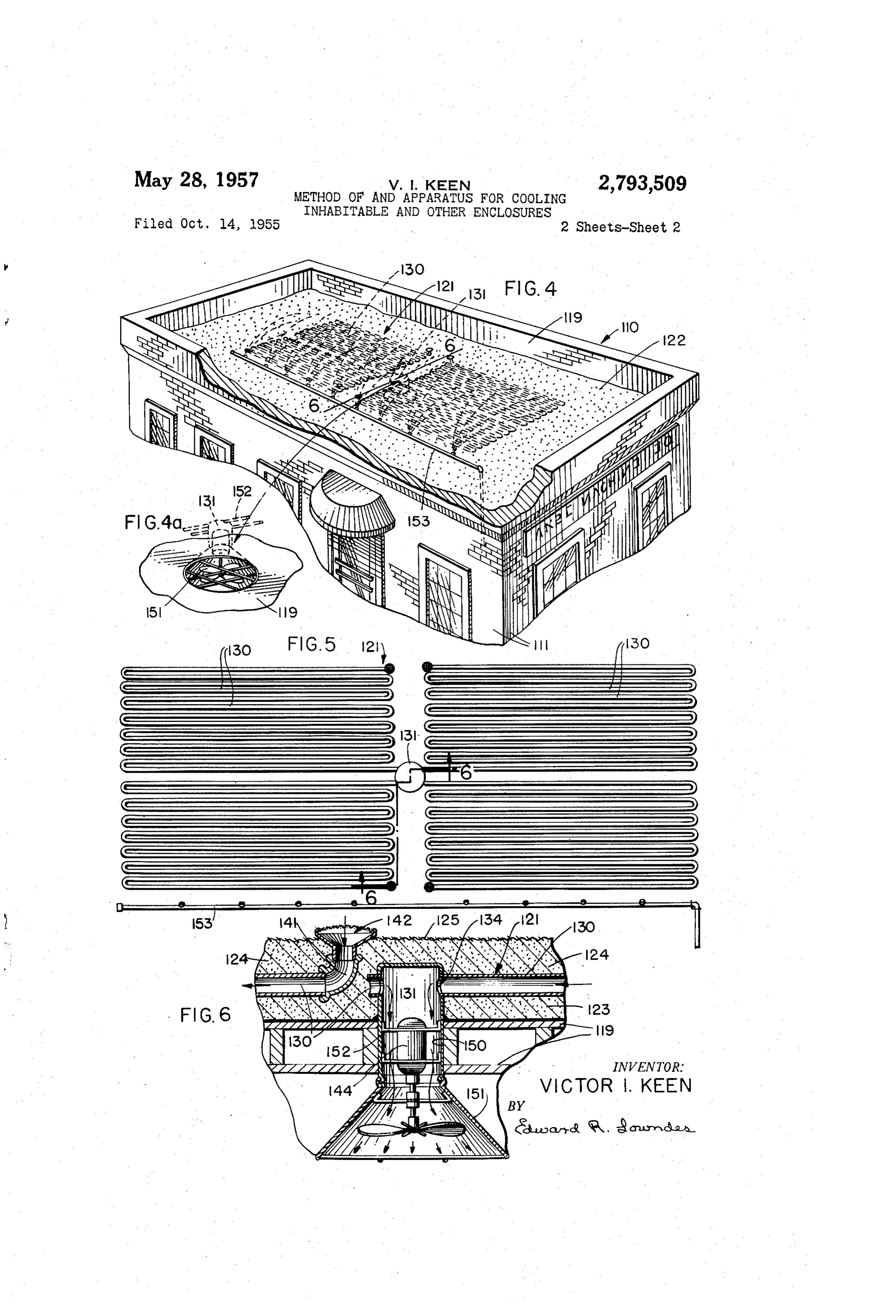
In the accompanying two sheets of drawings forming The heat exchange unit thus embedded in the artificial a part of this specification, two embodiments of the in bed 22 is comprised of a series of elongated tubular mem vention have been shown, bers 30 arranged in substantial parallelism and in a gen In these drawings: erally horizontal direction but with a slight deviation Fig. 1 is a fragmentary perspective view of an air from the horizontal for purposes that will be set forth cooling and dehumidifying apparatus constructed in ac presently. The members 30 are preferably in the form cordance with the principles of the present invention 30 of plastic pipes or conduits which may be on the order showing the same operatively associated with a typical of approximately two inches in diameter, and each of the dwelling house for air conditioning purposes. conduits 30 communicates at its forward end with a Fig. 2 is a plan view of a heat exchange unit em common manifold or header conduit or pipe 31 having ployed in connection with the installation shown in Fig. one end 29 closed and of larger diameter, preferably on 1. 35 the order of approximately six inches in diameter. It Fig. 3 is an enlarged sectional view taken substantially will be understood of course that the particular size of the along the line 3-3 of Fig. 1 in the direction indicated conduits 30 and 31 may be varied to suit differing instal by the arrows. lations and likewise the specific number of the conduits Fig. 4 is a fragmentary sectional view similar to Fig. 1 30 employed may be varied. For illustrative purposes showing a modified form of the apparatus showing the 40 only, thirty of these latter conduits have been shown in same operatively associated with an office building. the drawings.
Fig. 4a is fragmentary detail perspective view of an air Each of the conduits 30 is formed with an elongated inlet employed in connection with the form of the inven section or portion 32 which extends substantially parallel tion shown in Fig. 4. to the header conduit 31 with the various sections 30 Fig. 5 is a plan view of the heat exchange unit em 45 being arranged in number equally on opposite sides of the ployed in connection with the installation of Fig. 4, and axis of the conduit 31. The forward regions of the Fig. 6 is a vertical sectional view taken substantially various sections 30 are turned inwardly as at 33 so that along the line 6-6 of Fig. 4. these sections of the conduits on opposite sides of the In all of the above described views, similar characters conduit 31 converge toward each other in parallelism and of reference are employed to designate similar parts 50 the extreme forward ends of the sections 33 communicate throughout. with the interior of the conduit 31 through preformed Referring now to the drawings in detail and in particu openings 34 (Fig. 2) in the latter section which are ar lar to Figs, 1 to 3 inclusive wherein one form of the ranged uniformly in spaced relationship on opposite sides present invention is shown as being applied to the air of the section. The conduit 3 is likewise formed of a
conditioning of a typical residential dwelling house, the 55 suitable plastic material and the openings 34 therein are building is designated in its entirety at 10 and comprises formed to have a diameter slightly smaller than the over the usual outer walls 11 defining an inner enclosure all diameter of the tubular conduits 33 so that in the in 12 which may be partitioned in any suitable manner to stallation or assembly of the heat exchange unit 21 the accommodate the occupants thereof. The building 10 is forward ends of the conduits 30 are inserted into the shown as having installed therein the usual heating unit 60 openings 34 with a forced fit, the union being a perma 13 from which suitable conventional ducts 14 may extend nent one with good sealing characteristics. to the partitioned compartments or rooms of the en Referring now to Fig. 3, it will be noted that the com closure 12. The surrounding terrain 15 has its ground mon plane of the various conduits 30 deviates slightly level or line designated at 16 with the sub-terrain or base from the horizontal as represented by the broken line ment portion of the building 10 being shown in dotted 65 H-H. The slope of the conduits may be on the order lines at 17. The ground floor 18 of the building may be of 4 which is sufficient to allow for drainage of con provided with suitable registers 26 in communication with densation liquid from the conduits whenever such liquid the ducts 14 respectively. The above described arrange is present. Although the plastic conduits 30 are illus ment of the building 10 is purely conventional and no trated herein as being perfectly linear or straight, it will claim is made herein to any novelty associated with the 70 be understood that since these members are somewhat same, the novelty of the present invention residing rather flexible, they may deviate slightly from their straight line in the construction and arrangement of the air condition relationship of parallelism and follow shallow undulations ing apparatus whereby a supply of cooled and dehumidi in the surface of the gravel bed 22 on which they lie as fied air may be conducted to the enclosure 12 and which well as deviating slightly from their exact positions of will now be described in detail. , 75 parallelism as shown in the drawings. In other words
Page 5
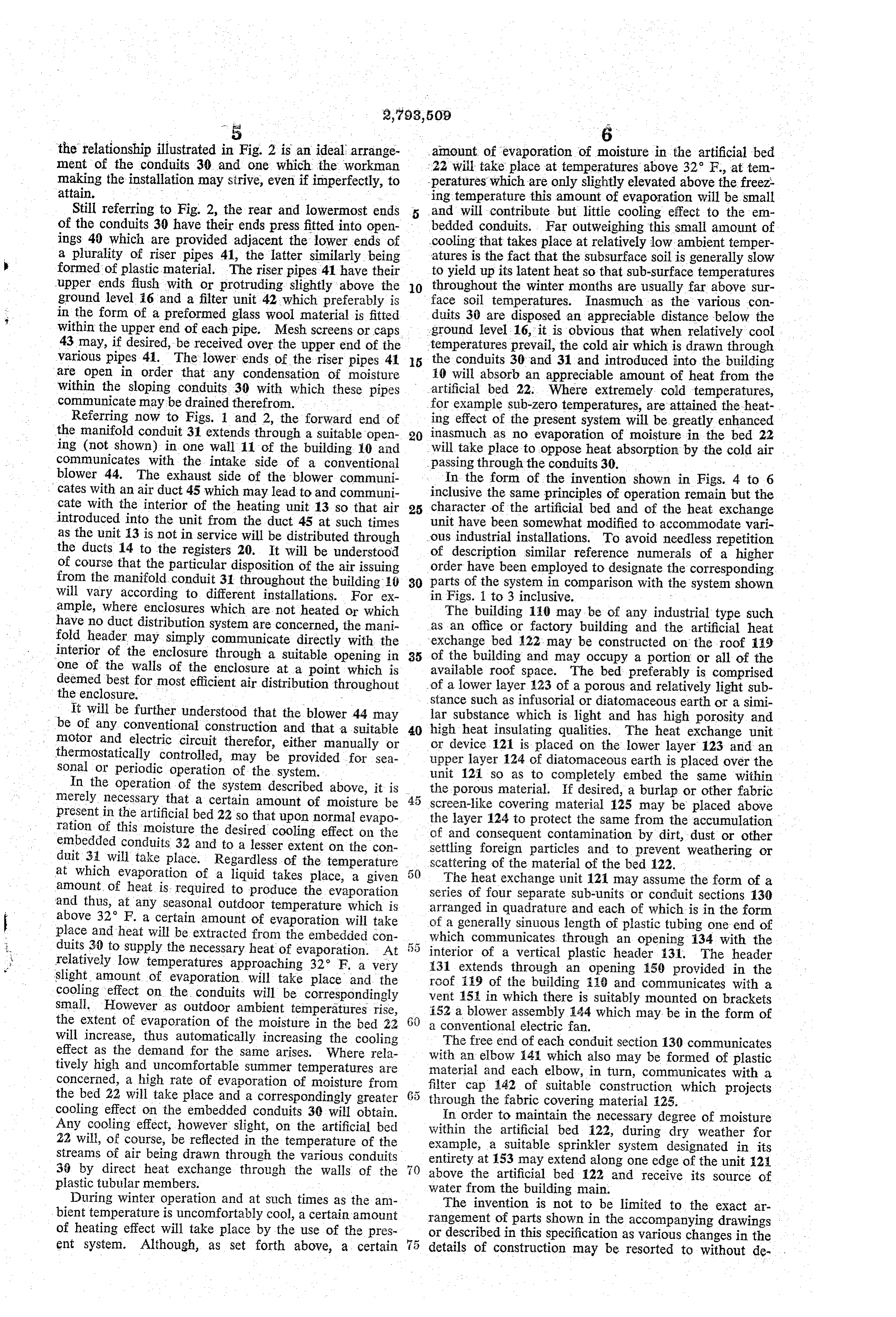
the relationship illustrated in Fig. 2 is an ideal arrange amount of evaporation of moisture in the artificial bed ment of the conduits 30 and one which the Workman 22 will take place at temperatures above 32 F., attem making the installation may strive, even if imperfectly, to peratures which are only slightly elevated above the freez: attain. ing temperature this amount of evaporation will be Small Still referring to Fig. 2, the rear and lowermost ends and will contribute but little cooling effect to the en of the conduits 30 have their ends press fitted into open bedded conduits. Far outweighing this small amount of ings 40 which are provided adjacent the lower ends of cooling that takes place at relatively low ambient temper a plurality of riser pipes 41, the latter similarly being atures is the fact that the subsurface soil is generally slow formed of plastic material. The riser pipes. 41 have their to yield up its latent heat so that sub-surface temperatures upper ends flush with or protruding slightly above the O throughout the winter months are usually far above Sur ground level 6 and a filter unit 42 which preferably is face soil temperatures. Inasmuch as the various con in the form of a preformed glass wool material is fitted duits 30 are disposed an appreciable distance below the within the upper end of each pipe. Mesh screens or caps ground level 16, it is obvious that when relatively cool 43 may, if desired, be received over the upper end of the temperatures prevail, the cold air which is drawn through various pipes 41. The lower ends of the riser pipes 41 5 the conduits 30 and 31 and introduced into the building are open in order that any condensation of moisture 10 will absorb an appreciable amount of heat from the within the sloping conduits 30 with which these pipes artificial bed 22. Where extremely cold temperatures, communicate may be drained therefrom. for example sub-zero temperatures, are attained the heat Referring now to Figs. 1 and 2, the forward end of ing effect of the present system will be greatly enhanced the manifold conduit 31 extends through a suitable open 20 inasmuch as no evaporation of moisture in the bed 22 ing (not shown) in one wall 11 of the building 10 and will take place to oppose heat absorption by the cold air communicates with the intake side of a conventional passing through the conduits 30. blower 44. The exhaust side of the blower communi In the form of the invention shown in Figs. 4 to 6 cates with an air duct 45 which may lead to and communi inclusive the same principles of operation remain but the cate with the interior of the heating unit 13 so that air 25 character of the artificial bed and of the heat exchange introduced into the unit from the duct 45 at such times unit have been somewhat modified to accommodate vari as the unit 13 is not in service will be distributed through ous industrial installations. To avoid needless repetition the ducts 14 to the registers 20. It will be understood of description similar reference numerals of a higher of course that the particular disposition of the air issuing order have been employed to designate the corresponding from the manifold conduit 31 throughout the building 10 30 parts of the system in comparison with the system shown will vary according to different installations. For ex in Figs. 1 to 3 inclusive.
ample, where enclosures which are not heated or which The building 110 may be of any industrial type such have no duct distribution system are concerned, the mani as an office or factory building and the artificial heat fold header may simply communicate directly with the exchange bed 122 may be constructed on the roof 119 interior of the enclosure through a suitable opening in 35 of the building and may occupy a portion or all of the one of the walls of the enclosure at a point which is available roof space. The bed preferably is comprised deemed best for most efficient air distribution throughout of a lower layer 123 of a porous and relatively light Sub the enclosure. stance such as infusorial or diatomaceous earth or a simi It will be further understood that the blower 44 may lar substance which is light and has high porosity and be of any conventional construction and that a suitable 40 high heat insulating qualities. The heat exchange unit notor and electric circuit therefor, either manually or or device.121 is placed on the lower layer 123 and an thermostatically controlled, may be provided for sea upper layer 124 of diatomaceous earth is placed over the Sonal or periodic operation of the system. unit 121 so as to completely embed the same within In the operation of the system described above, it is the porous material. If desired, a burlap or other fabric merely necessary that a certain amount of moisture be screen-like covering material 125 may be placed above present in the artificial bed 22 so that upon normal evapo the layer 124 to protect the same from the accumulation ration of this moisture the desired cooling effect on the of and consequent contamination by dirt, dust or other embedded conduits 32 and to a lesser extent on the con duit 31 will take place. Regardless of the temperature settling scattering foreign particles and to prevent weathering or of the material of the bed 122.
at which evaporation of a liquid takes place, a given amount of heat is required to produce the evaporation series of fourexchange
The heat unit 121 may assume the form of a and thus, at any seasonal outdoor temperature which is arranged in quadrature sub-units separate and each or conduit sections 130 of which is in the form above 32 F. a certain amount of evaporation will take of a generally sinuous length of plastic tubing one end of place and heat will be extracted from the embedded con duits 30 to Supply the necessary heat of evaporation. At interior of a vertical plastic header 131. 134
which communicates through an opening
The with the header relatively low temperatures approaching 32° F. a very slight amount of evaporation will take place and the 131 extends through an opening 50 provided in the roof 19 of the building 18 and communicates with a cooling effect on the conduits will be correspondingly vent
Small. However as outdoor ambient temperatures rise, 152 a15blower in which there is suitably mounted on brackets the extent of evaporation of the moisture in the bed 22 60 a conventionalassembly 144 which may be in the form of electric fan.
will increase, thus automatically increasing the cooling The free end of each conduit section 130 communicates effect as the demand for the same arises. Where rela with an elbow i41 which also may be formed of plastic tively high and uncomfortable summer temperatures are material and each elbow, in turn, communicates with a concerned, a high rate of evaporation of moisture from the bed 22 will take place and a correspondingly greater filter cap 142 of suitable construction which projects through the fabric covering material 25.
cooling effect on the embedded conduits 30 will obtain. In order to maintain the necessary degree of moisture Any cooling effect, however slight, on the artificial bed within the artificial bed 122, during dry weather for 22 will, of course, be reflected in the temperature of the example, a suitable sprinkler system designated in its streams of air being drawn through the various conduits 36 by direct heat exchange through the walls of the above the 153 entirety at may extend along one edge of the unit 24 artificial bed 122 and receive its source of plastic tubular members.
During winter operation and at such times as the am water from the building main.
The invention is not to be limited to the exact ar bient temperature is uncomfortably cool, a certain amount rangement of parts shown in the accompanying drawings of heating effect will take place by the use of the pres or described in this specification as various changes in the ent system. Although, as set forth above, a certain details of construction may be resorted to without de
Page 6
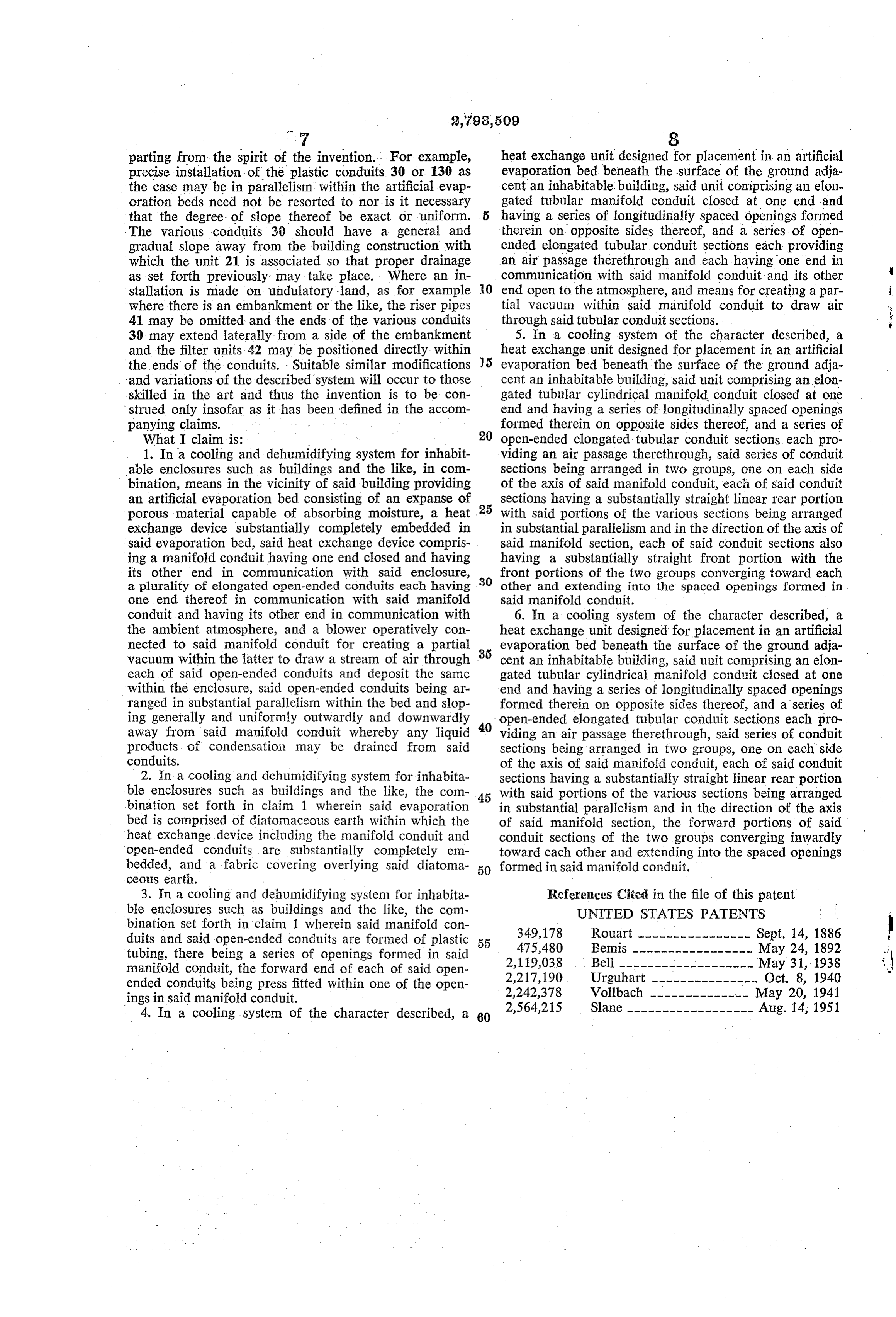
parting from the spirit of the invention. For example, heat exchange unit designed for placement in an artificial precise installation of the plastic conduits 30 or 130 as evaporation bed beneath the surface of the ground adja the case may be in parallelism within the artificial evap cent an inhabitable. building, said unit comprising an elon oration beds need not be resorted to nor is it necessary gated tubular manifold conduit closed at one end and that the degree of slope thereof be exact or uniform. having a series of longitudinally spaced openings formed - The various conduits 30 should have a general and therein on opposite sides thereof, and a series of open gradual slope away from the building construction with ended elongated tubular conduit sections each providing which the unit 21 is associated so that proper drainage an air passage therethrough and each having one end in as set forth previously may take place. Where an in communication with said manifold conduit and its other stallation is made on undulatory land, as for example O end open to the atmosphere, and means for creating a par where there is an embankment or the like, the riser pipes tial vacuu m within said manifold conduit to draw air 41 may be omitted and the ends of the various conduits through said tubular conduit sections. 30 may extend laterally from a side of the embankment 5. In a cooling system of the character described, a and the filter units 42 may be positioned directly within heat exchange unit designed for placement in an artificial the ends of the conduits. Suitable similar modifications 5 evaporation bed beneath the surface of the ground adja and variations of the described system will occur to those cent an inhabitable building, said unit comprising an elon skilled in the art and thus the invention is to be con gated tubular cylindrical manifold conduit closed at one strued only insofar as it has been defined in the accom end and having a series of longitudinally spaced openings panying claims. formed therein on opposite sides thereof, and a series of What I claim is: open-ended elongated tubular conduit sections each pro 1. In a cooling and dehumidifying system for inhabit viding an air passage therethrough, said series of conduit able enclosures such as buildings and the like, in com sections being arranged in two groups, one on each side bination, means in the vicinity of said building providing of the axis of said manifold conduit, each of said conduit an artificial evaporation bed consisting of an expanse of sections having a Substantially straight linear rear portion porous material capable of absorbing moisture, a heat 25 With said portions of the various sections being arranged exchange device substantially completely embedded in in substantial parallelism and in the direction of the axis of said evaporation bed, said heat exchange device compris said manifold section, each of Said conduit sections also ing a manifold conduit having one end closed and having having a substantially straight front portion with the its other end in communication with said enclosure, front portions of the two groups converging toward each a plurality of elongated open-ended conduits each having 30 other and extending into the spaced openings formed in one end thereof in communication with said manifold said manifold conduit.
conduit and having its other end in communication with 6. In a cooling system of the character described, a the ambient atmosphere, and a blower operatively con heat eXchange unit designed for placement in an artificial nected to said manifold conduit for creating a partial evaporation bed beneath the surface of the ground adja vacuum within the latter to draw a stream of air through 35 cent an inhabitable building, said unit comprising an elon each of said open-ended conduits and deposit the same gated tubular cylindrical manifold conduit closed at one within the enclosure, said open-ended conduits being ar end and having a series of longitudinally spaced openings ranged in substantial parallelism within the bed and slop formed therein on opposite sides thereof, and a series of ing generally and uniformly outwardly and downwardly open-ended elongated tubular conduit Sections each pro away from said manifold conduit whereby any liquid 40 viding an air passage therethrough, said Series of conduit products of condensation may be drained from said Sections being arranged in two groups, one on each side conduits. of the axis of said manifold conduit, each of said conduit 2. In a cooling and dehumidifying system for inhabita sections having a substantially straight linear rear portion ble enclosures such as buildings and the like, the com with said portions of the various sections being arranged bination set forth in claim 1 wherein said evaporation in substantial parallelism and in the direction of the axis bed is comprised of diatomaceous earth within which the of said manifold section, the forward portions of said heat eXchange device including the manifold conduit and conduit sections of the two groups converging inwardly open-ended conduits are Substantially completely en toward each other and extending into the spaced openings bedded, and a fabric covering overlying said diatoma 50 formed in said manifold conduit.
ceous earth.
3. In a cooling and dehumidifying system for inhabita References Cited in the file of this patent ble enclosures such as buildings and the like, the com UNITED STATES PATENTS bination set forth in claim 1 wherein said manifold con
duits and said open-ended conduits are formed of plastic 55 475,480 Rouart ---------------- Sept. 14, 1886 tubing, there being a series of openings formed in said Bemis ----------------- May 24, 1892 manifold conduit, the forward end of each of said open 2,119,038 Bell ------------------- May 31, 1938 ended conduits being press fitted within one of the open 2,217,190 Urguhart --------------- Oct. 8, 1940 ings in Said manifold conduit. 2,242,378 Vollbach -------------- May 20, 1941 4. In a cooling system of the character described, a 2,564,215
Provenance
- Collection
- Cited prior art
- Original PDF
- patentimages.storage.googleapis.com →
- Filed
- 1955-10-14
- Pages
- 6
- Method
- pdftotext (the PDF's own text layer) + pdftoppm 300dpi page scans
- Source
- Google Patents bibliographic record
- Granted
- 1957-05-28
- Inventors
- Victor I Keen
- Transcribed from
- patentimages.storage.googleapis.com →