patent · US4090485
Fuel systems for internal combustion engines
23 May 1978
Page 1 — bibliographic record
United States Patent (19) 11 4,090,485 LaCreta 45 May 23, 1978 54 FUEL SYSTEMS FOR INTERNAL 2,884,917 5/1959 Quinby ................................. 123/133 COMBUSTON ENGINES 3,174,472 3/1965 Balogh................................. 261/16 3,913,545 10/1975 Hasse et al. .......................... 123/121 (75) Inventor: Mario V. LaCreta, Kent, Ohio 3,970,054 7/1976 Henault et al. ... ... 123/DIG. 12 4,011,847 3/1977 Fortino ................................ 123/121 (73) Assignee: Antonio LaCreta, Scottsdale, Ariz.; a 4,033,133 7/1977 Houseman et al. .................... 48/107 part interest 4,040,403 8/1977 Rose et al. ........................... 123/133 21 Appl. No.: 782,177 Primary Examiner-S. Leon Bashore 22 Filed: Mar. 28, 1977 Assistant Examiner-George C. Yeung Attorney, Agent, or Firn-Warren F. B. Lindsley (51) Int. C.’............................................. FO2M 17/18 (52) U.S. C. ...................................... 123/133; 48/107; 57 AESTRACT 48/180 C; 123/DIG. 12; 261/16; 261/98 A fuel vaporization system for hydrocarbon users, such (58) Field of Search ....... 48/107,93, 199 R, 199 FM, as internal combustion engines, gas turbines and the like 48/219, 211, 212, 180 C, 180 F; 261/16, 96, 98; wherein the prior art gas generating and carburetor
functions are accomplished in a novel chamber or fuel 56) References Cited generator with additional benefits afforded through the
1,947,129 2/1934 Hyma ..................................... 261/16 10 Clains, 5 Drawing Figures
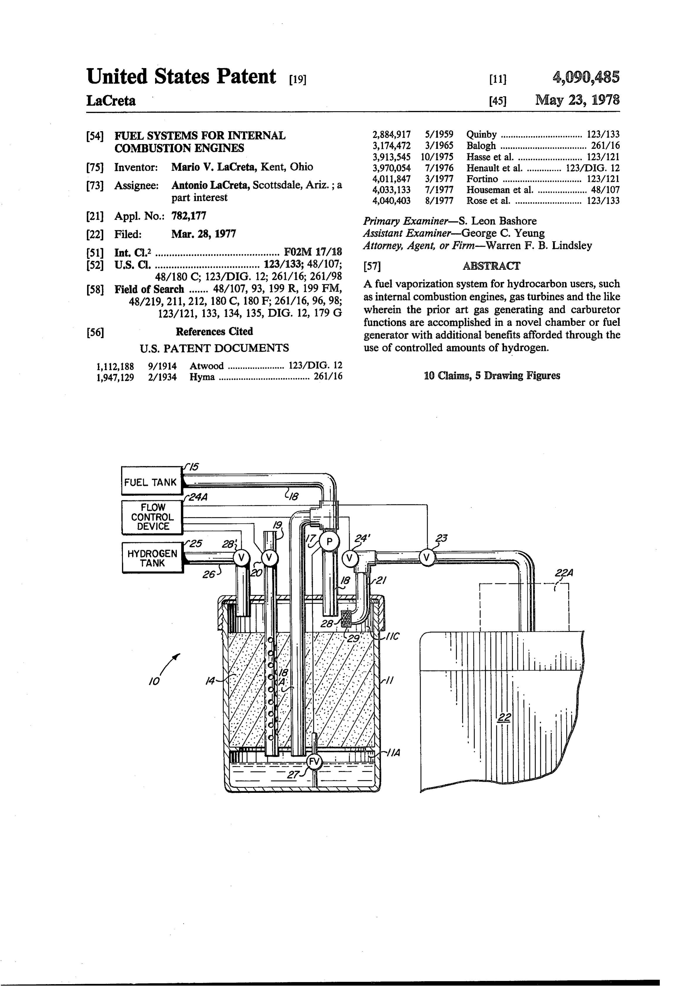
FUEL ANK 24A F.A3
FLOW
HYDROGEN
ANK
Page 2
Drawing sheet — no readable text.
Page 3
Further objects and advantages of the invention will
FUEL SYSTEMS FOR INTERNAL COMBUSTION become apparent as the following description proceeds ENGINES and the features of noveity which characterize the in BACKGROUND OF THE INVENTION vention will be pointed out with particularity in the claims annexed to and forming a part of this specifica
The rising cost of gasoline and the growing aware tion.
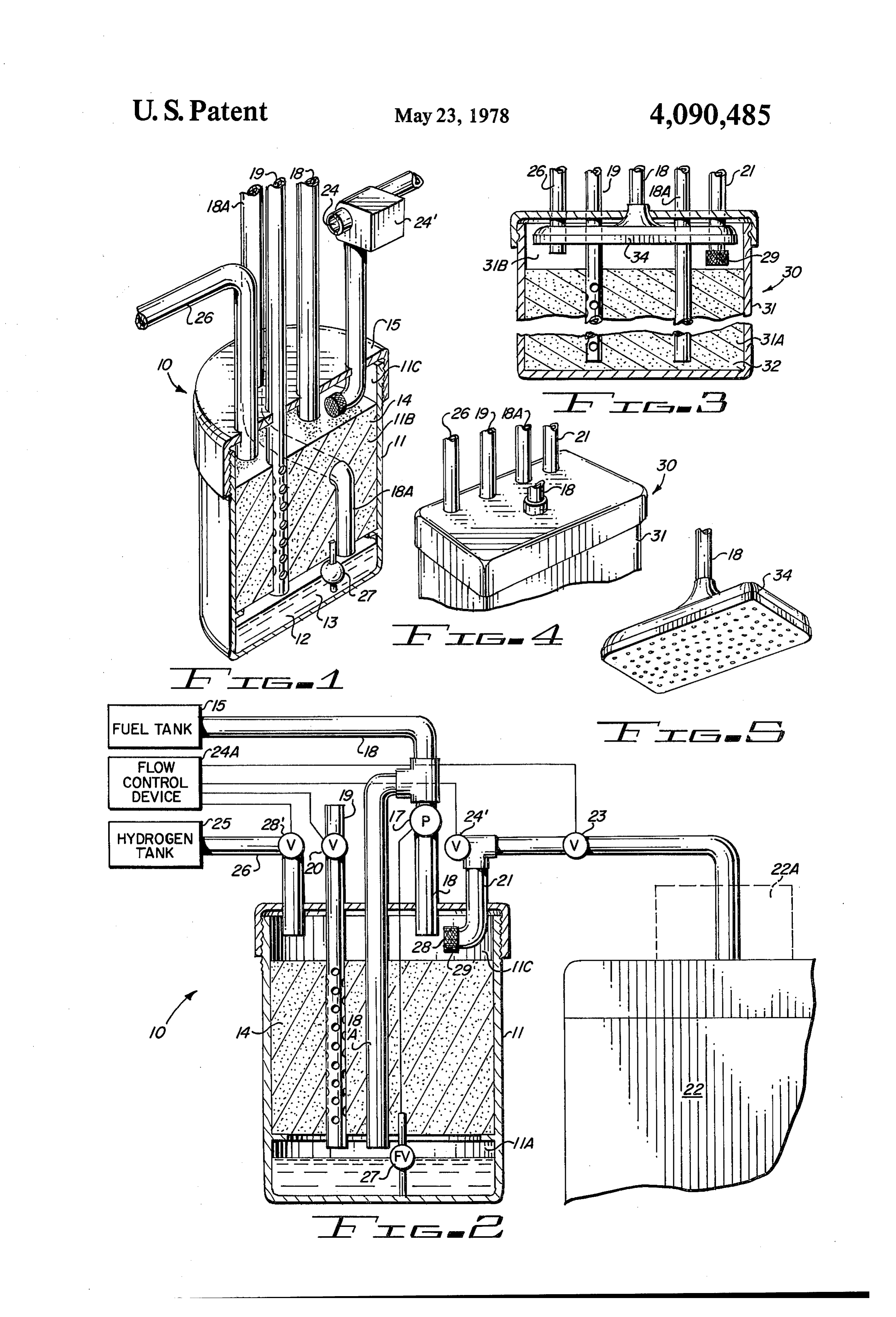
ness of the nation's dwindling oil reserves emphasize the BRIEF DESCRIPTION OF THE DRAWING urgency for the attainment of improved efficiency in gasoline and other hydrocarbon burning engine perfor The present invention may be more readily described aC. O by reference to the accompanying drawing, in which: At the same time, there is a widespread determination FIG. 1 is a partial perspective view of a fuel genera to end or greatly reduce the level of atmospheric pollu tor for a hydrocarbon burning engine and embodying tion to which the automobile has contributed. the invention;
Because the proper performance of the carburetor is FIG. 2 is a functional diagram of an improved fuel essential to the realization of both of these goals, signifi 15 generating system utilizing the fuel generator shown in cant improvements in carburetor-type systems are ur FIG, 1;
gently needed. FIG. 3 is a cross-sectional view of a modification of The conventional carburetor as employed in today's the fuel generator shown in FIG. 1;
automobile is a complex mechanical device comprising FIG. 4 is a partial perspective view of the top, left as many as six separate systems, i.e. a float system for 20 end and front of the fuel generator shown in FIG. 3; and controlling the level of fuel in the bowl, a low-speed or FIG. 5 is a perspective view of the bottom, front and idling system, a high-speed or cruising system, an accel right end of the fuel spray head shown in FIG. 3. erating pump system, and power and choke systems. In DESCRIPTION OF THE PREFERRED addition, there are anti-percolation vents, hot idle com EMBODIMENT pensators, anti-dieseling solenoids, deceleration con 25 trols, etc. Referring more particularly to the drawing by char This multitude of special systems and features re acters of reference, FIG. 1 discloses an improved fuel quires careful adjustment and maintenance and the generator 10 comprising a vaporization chamber 11 many small ducts and valves are vulnerable to blockage having three interconnected zones, i.e. a liquid zone and wear by dust and dirt particles finding their way 30 11A for containing suitable liquids such as hydrocar through the air filter. bons including, for example, gasoline 12 at the lower Furthermore, until recently, there has been a greater end 13 of the chamber, a vaporization zone 11B for said emphasis on certain aspects of performance such as liquid intermediate the ends of chamber 11 containing a starting, acceleration and power developed with too porous material 14, and a vapor zone 11C providing a little emphasis given to gasoline mileage and atmo 35 space at the top end 15 of the chamber for collection spheric pollution. The sudden change in emphasis and mixing of fuel vapors. A suitable hydrocarbon sup toward improved fuel economy and reduced atmo ply such as gasoline is furnished from a gasoline tank 15 spheric pollution calls for a radical new approach to shown in FIG. 2 of an automobile or other device fuel vaporization or gasification system for the internal which is transmitted by pump 7 through a fuel line or combustion engines as opposed to the enhancement of 40 conduit 18 to zone 11C of chamber 11 from which zone today's carburetors by the addition of still more vents, it percolates or filters through to zone 11A, leaving the valves and modified venturies. interior of the porous material in zone 11B wet with SUMMARY OF THE INVENTION finely divided droplets of gasoline. An apertured air intake conduit means 19 is provided for supplying atmo
In accordance with the invention claimed, an im 45 spheric air into the porous material 14 in zone 11B of proved fuel generation system is provided for the va chamber 11 through a control valve 20 and into an air porization, aeration, gasification and humidification of space in zone 11A above the gasoline in this zone. hydrocarbontype fuels prior to their introduction into a As evident from FIGS. 1 and 2 of the drawing, a fuel consuming engine. line 21 interconnects the air space in zone 11C of cham It is, therefore, one object of this invention to provide 50 ber 11 directly to an internal combustion engine 22 an improved fuel generating system for hydrocarbon through a regulator valve 23 or to and through a carbu burning engines. retor 22A to internal engine 22. Line 2 is conformed to Another object of this invention is to provide such an provide an opening 24 to atmosphere in the form of a improved fuel generating system which achieves valve means for providing a venturi action for injecting greater fuel economy by virtue of its capability for 55 air into the fuel line 21 for further mixing purposes aided supplying a more uniform mixture of air and hydrocar by the negative pressure or suction of engine 22 in the bon fumes. drawing of fuel vapors from the vapor space 11C of A further object of this invention is to provide such a chamber 11 directly or through a carburetor into the fuel generating system which achieves greater fuel manifold of the internal combustion engine or any other economy by virtue of its capability for converting the 60 vapor burning device.
entrained fuel into more finely divided particles. In order to supplement or fortify the hydrocarbon A still further object of this invention is to provide fumes or mixture supplied engine 22, such as gasoline, such an improved fuel generating system in which the through the fuel line 21, a source of hydrogen 25 under fuel-air mixture is fortified with hydrogen to enhance pressure is connected via gas line 26 through control the fuel economy, 65 valve 28' to the vapor space 11C of chamber 11, Valve Yet another object of the invention is to provide a 28' regulates and controls the flow of hydrogen to the cleaner fuel burn with the result that oil changes will be vapor space of chamber i.
required less frequently than for a conventional system. The vaporization and fuel generating chamber 11
Page 4
holds a controlled amount of a hydrocarbon fuel, such 18, air intake conduit means 19 and fuel lines 21 and 26 as gasoline 12, in zone 11A which may be held at a of FIGS. 1 and 2.
desired level by means of a suitable float operated valve It should be noted that the fuel generator 30 differs arrangement 27 associated with line 18 which controls from fuel generator 10 of FIGS. 1 and 2 in that it merely the fuel supplied to zone 11C by fuel pump 17. Further, comprises a two-zone generator having an apertured the return fuel line 18A connected to zone 11A is spray head 34 fastened to the end of fuel line 18 in space provided for drawing back into zone 11C through the 31B directly over the porous material 32 in zone 31A. action of pump 17 the residue of fuel in Zone 11A. Thus, the fuel introduced into the fuel generator is dis The humidifying gasification chamber 11 holds a persed evenly across the top of the porous material for controlled amount of porous material 14 which is se 10 percolating through the porous material, and may be lected for its ability to absorb and disperse hydrocarbon used in the structure of FIGS. 1 and 2 to accomplish the fuels or their vapors throughout its configuration same results.
thereby providing a large vaporization surface for the Although but two embodiments of the invention have fuel, such as gasoline, in either its liquid or vapor state been to provide a continuous supply of hydrocarbon vapors 15 those illustrated and described, it will be apparent to skilled in the art that various changes and modifi or fumes to the space 11C of chamber 11.
As noted from FIG. 1 of the drawing, chamber 11 cations of the may be made without departing from the spirit invention or the scope of the appended claims.
comprises an airtight tank having suitable ports for air What is claimed is:
and fuel intake and an outlet port for conducting the 1. A fuel system for liquid hydrocarbon burning en vaporized fuel to engine 22. 20 gines comprising in combination:
Zone 11B of chamber 11 may be filled with a porous a chamber having fluid inlet and outlet ports and resilient material such as foam rubber which absorbs the defining a vaporization zone and a vapor collecting fuel metered into zone 11A of chamber 11 through fuel and mixing zone, line 18. The porous material 14 suspends the fuel passing therethrough in such a manner as to render it more 25 means for connecting a source of liquid hydrocarbon fuel under pressure through said fluid inlet port to vaporizable. It should be recognized that other means said vaporization zone, of vaporizing or gasification of the fuel may be used in an air intake manifold connected to said vaporization lieu of the porous material 14 and still fall within the zone of said chamber, scope of this invention.
The fuel line inlet port 28 in the vaporizing space of 30 saidairintake manifold providing a means for dispersing throughout said vaporization zone for aiding in zone 11C at the top of chamber 11 may be provided the vaporizing of the fuel dispersed throughout the with a diffusing drip ring 29 to aid in maintaining or revaporizing any condensation of the gasoline in fuel vaporization zone, line 21. Further, if the disclosed device is used indepen a first conduit means leading from said outlet port of dently of and in lieu of a carburetor, the regulator con 35 said chamber arranged in said collecting and vapor trol valve 23 may be provided in the fuel line to control mixing zone to either a hydrocarbon burning en the fuel flow to engine 22 in the manner of the known gine or carburetor therefore, accelerator pedal in an automobile. said first conduit means being provided with an air It has been observed that after a short period of time, intake port for injecting air into said first conduit such as twenty or thirty minutes of engine running time, means under negative pressure of the engine used the amount of air introduced in fuel line 21 through with said fuel system, opening 24 may be reduced since the residue of gasoline a second conduit means leading from a source of remaining in zone 11A of chamber 11 is less volatible hydrogen to said collecting and mixing zone, than the fresh gasoline furnished chamber 11 from tank valve means for selectively controlling the flow of 16. This residue in zone 11A may be rendered highly 45 hydrogen through said second conduit means into volatible by the introduction into zone 11C of the cham said collecting and mixing zone, and ber a controlled amount of hydrogen. The minute porous material positioned within said vaporization amount of hydrogen introduced into chamber 11 not zone for dispersing said fuel in the form of finely only eliminates the need for reducing the air input into divided droplets, said air from said air intake mani the fuel line 21 through port 24 after a period of engine 50 fold vaporizing the droplets into fumes throughout operation but also mixes with the residue of any hard said vaporization zone.
to-vaporize residue of gasoline in zone 11A to make it 2. The fuel system set forth in claim 1 wherein: more volatible, thereby improving engine performance. said porous material comprises a resilient material. The amount of air injected into fuel line 21 through the 3. The fuel system set forth in claim 1 wherein: venturi action of the valve means 24' associated with 55 said porous material comprises foam rubber. opening 24 is controlled by a suitable flow control de 4. The fuel system for hydrocarbon burning engines vice 24A. This flow control device 24A may comprise set forth in claim 1 wherein:
the gas pedal of engine 22 or any other easily operated said chamber also having means defining a liquid fuel control regulator. It should be recognized that the ZOc.
amount and control of air introduced through opening 5. The fuel system set forth in claim 4 in further com 24 is essential to the effective operation of the invention bination with:
disclosed and claimed herein. a valve means in said first conduit means for control FIGS. 3, 4 and 5 of the drawing illustrate a modifica ling the flow of vaporized fuel from said collection tion of the fuel generator 10 shown in FIGS. 1 and 2 and mixing zone to the engine. wherein fuel generator 30 comprises a chamber 31 hav 65 6. The fuel system set forth in claim 1 wherein: ing a Zone 31A containing a porous material 32 and a said first conduit means further comprises a valve vapor zone 31B provided at the top end 33 of the cham means for performing a venturi action for aiding in ber. This generator is provided with the same fuel line drawing air from said vaporization zone.
Page 5
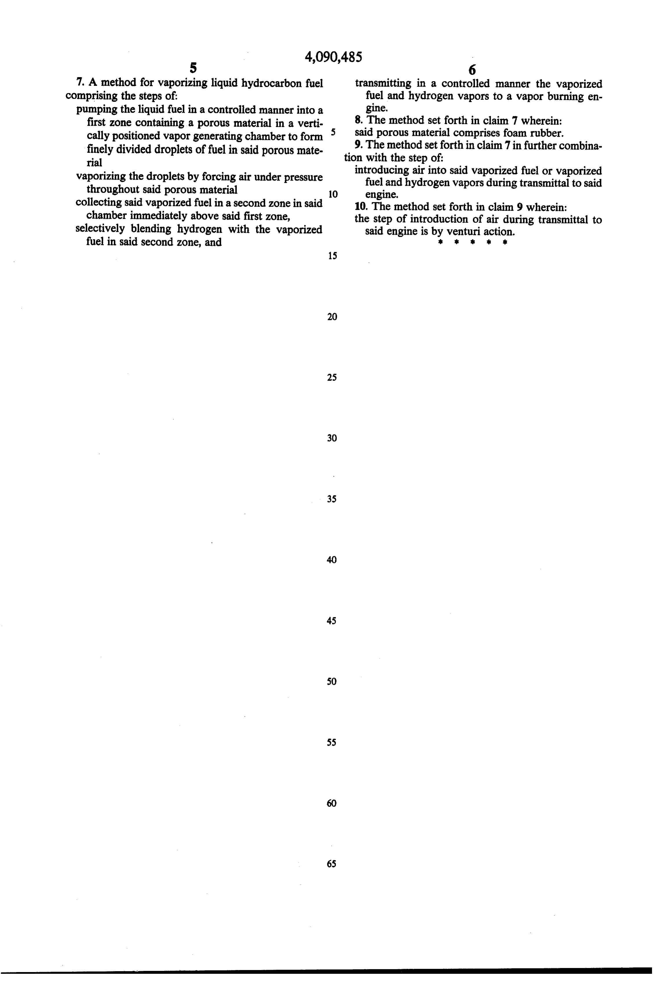
7. A method for vaporizing liquid hydrocarbon fuel transmitting in a controlled manner the vaporized comprising the steps of fuel and hydrogen vapors to a vapor burning en pumping the liquid fuel in a controlled manner into a gine.
first zone containing a porous material in a verti 8. The method set forth in claim 7 wherein: cally positioned vapor generating chamber to form 5 said porous material comprises foam rubber. finely divided droplets of fuel in said porous mate 9. The method set forth in claim 7 in further combina rial tion with the step of:
vaporizing the droplets by forcing air under pressure introducing air into said vaporized fuel or vaporized throughout said porous material fuel and hydrogen vapors during transmittal to said
collecting said vaporized fuel in a second zone in said 10. The method set forth in claim 9 wherein: chamber immediately above said first zone, the step of introduction of air during transmittal to selectively blending hydrogen with the vaporized said engine is by venturi action. fuel in said second zone, and is k is :
Provenance
- Collection
- Cited prior art
- Original PDF
- patentimages.storage.googleapis.com →
- Filed
- 1977-03-28
- Pages
- 5
- Method
- pdftotext (the PDF's own text layer) + pdftoppm 300dpi page scans
- Source
- Google Patents bibliographic record
- Granted
- 1978-05-23
- Inventors
- Mario V. LaCreta
- Transcribed from
- patentimages.storage.googleapis.com →