patent · US10041432
Fuel system having pump prognostic functionality
7 August 2018
Page 1 — bibliographic record
|HAI LUI AUN ENTORN ULTIMI TOMUTO US010041432B2
(12) United States Patent ( 10) Patent No.: US 10 ,041,432 B2 Puckett et al. (45) Date of Patent: Aug. 7 , 2018 (54 ) FUEL SYSTEM HAVING PUMP (56 ) References Cited PROGNOSTIC FUNCTIONALITY U .S . PATENT DOCUMENTS (71 ) Applicant: Caterpillar Inc., Peoria , IL (US) 2 , 859,612 A 11/1958 Morse 5 , 117 ,683 A * 6 / 1992 Phillips ................ FO2M 65/008 (72) Inventors: Daniel Reese Puckett, Peoria , IL (US ); 73 / 114 . 38 Bradley Scott Bashore , Washington , IL 5 ,954,032 A * 9/1999 Augustin .......... FO2D 41/0087 (US); Michael Edward Sattler , 123/ 198 DB Galesburg , IL (US ); Michael Scott 5 , 974 , 865 A 11/ 1999 Dambach
Marchionda , Peoria , IL (US ); Sasidhar 701/ 114 Rayasam , Peoria , IL (US ); Kranti 7 , 360 ,408 B2 4 /2008 Dingler et al. Kumar Nellutla , Normal, IL (US ) (Continued ) (73 ) Assignee : Caterpillar Inc., Deerfield , IL (US) FOREIGN PATENT DOCUMENTS ( * ) Notice : Subject to any disclaimer, the term of this DE 102011102282 11/ 2012 patent is extended or adjusted under 35 JP 5217514 6 / 2013 U .S .C . 154 (b ) by 38 days. Primary Examiner — Hieu T Vo
Assistant Examiner — Sherman Manley (21) Appl. No.: 15 /401,911 (74 ) Attorney, Agent, or Firm — Finnegan , Henderson , Farabow , Garrett & Dunner, LLP
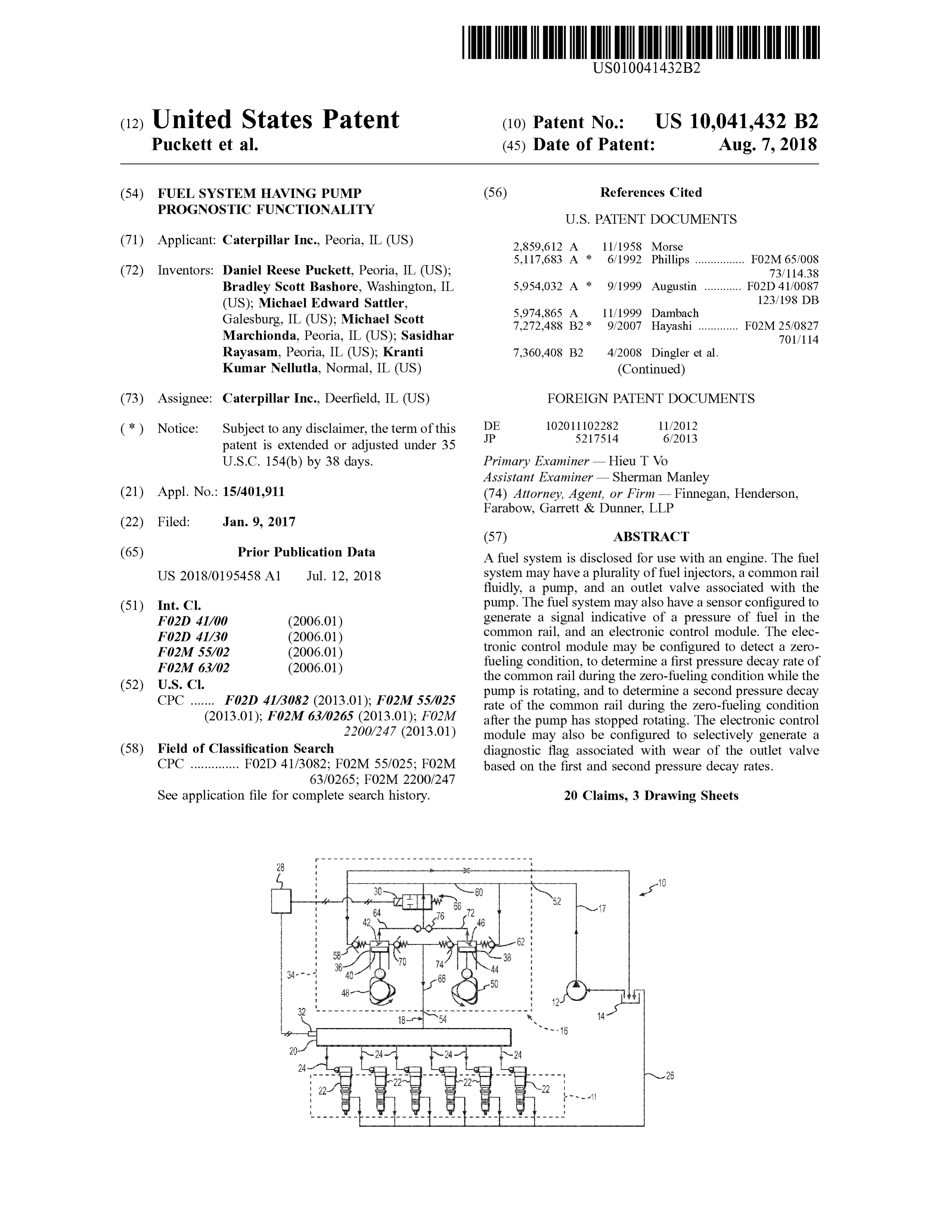
(65 ) Prior Publication Data A fuel system is disclosed for use with an engine. The fuel US 2018 /0195458 A1 Jul. 12, 2018 system may have a plurality of fuel injectors, a common rail fluidly, a pump, and an outlet valve associated with the (51) Int. CI. pump . The fuel system may also have a sensor configured to F02D 41/00 (2006 .01 ) generate a signal indicative of a pressure of fuel in the F02D 41/ 30 ( 2006 .01) common rail, and an electronic control module. The elec FO2M 55/ 02 ( 2006 .01) tronic control module may be configured to detect a zero FO2M 63/02 ( 2006 .01) fueling condition , to determine a first pressure decay rate of the common rail during the zero - fueling condition while the (52 ) U .S. CI. pump is rotating , and to determine a second pressure decay CPC ....... F02D 41/3082 (2013 .01 ); F02M 55/025 rate of the common rail during the zero -fueling condition (2013.01); FO2M 63/0265 (2013.01); F02M after the pump has stopped rotating . The electronic control 2200 /247 (2013.01 ) module may also be configured to selectively generate a (58 ) Field of Classification Search diagnostic flag associated with wear of the outlet valve CPC .............. FO2D 41 /3082 ; FO2M 55 /025 ; FO2M based on the first and second pressure decay rates .
See application file for complete search history. 20 Claims, 3 Drawing Sheets
- - - - - - - - - - - - - - - - - - - - - - - - - - - - - - - - - -
www . www. wwwwww w wwwwwwwwww
DLO
Low LAT wowo 38- 62 w
? ? ? ??? ? ?? ?? ? ?? ?? ? ? ??? ??? ? ? ? ?? ?????? ? ?? ?? ?? ?? ? 7 ? ? ? ??? ?? ? ?? ?, ?
- 22 TI - - -
wwwwwwwwwwwwwwwwwwwwwwwwwwwwwwvwmmm
Page 2
US 10 ,Page
U . S . PATENT DOCUMENTS
7 ,891,340 B2 * 2 /2011 Surnilla ................ FO2D 41/062
9 , 051,893 B2 * 6 / 2015 Jung ............... FO2D 41/ 221 2007/0079808 A1 * 4 /2007 Takahashi FO2D 41/ 221
2009 /0260601 A1* 10 / 2009 Ulrey .................. FO2B 1/ 12
2013/0013175 A1* 1/2013 Nistler . ................. FO2D 41/22
* cited by examiner
Page 3
U . S . Patent Aug. 7 , 2018 Sheet 1 of 3 US 10 ,041,432 B2
ohne LLLLL
mot
WWW
Wat
* * * ** * W * * * * * ** * ** * * *
the
SUKA
WwwWw wWw
7468 X * * ** * ** * * * ** ** * * ** *
serveren
wWw
LMOEM
Emoz
* w ansa
PAK N AM I
C W
ang
memenuhmmmmmmmmm w
? ?? ??? ?? ?? ? ? . ??? ?? ?? ?? ?? ?? ??? ?? ?? ??? ? ' ? ??? ?? ?? ??? ???mm
AAOM
Page 4
U . S . Patent Aug. 7 , 2018 Sheet 2 of 3 US 10 ,041,432 B2
CORSKO
KONGKCK
PREAS ULRE 210
w X 12 A an loc mo T3 TIME
FIG
como wwwwwwwwwwwwwwwwwww T2
Oberland * * * * * * * * * * * * * w * * T1
OFF
KEY pro * * * - - - ROCOOOOOOOCOSCOSOCOSCOSOOOOOOOOOOOOOOOOOOOOOOOOOOOOOOR * • • • • • - - To mmmmm
2000 1800 $ $ $. .z
RPM - SPEED ENGINE
* * * * * * * * * * * * * * * * * * * * * *** * * * * * * * * *
gegnog
Page 5
U . S . Patent Aug. 7 , 2018 Sheet 3 of 3 US 10 ,041,432 B2
21 min many
SETRALPRESSURE TO
UPPERLIMTOS
TUNEABLE RANGE
moon wwwwwwwwwwwwwwwww
PUMPS
AT ZERO
DISPLACEMENT TO DO
mons
DETERMINE PRESSURE
DECAY RATE BASED ON AO O
RECORO MEASUREMENT
Bikin Swanson
SPEED? AVERAGE POR AND * UM TOFTUNEABLEakw
RAMA
PRESSURE PI &
RECORD PA1
sprovo
WAT TUNEABLE THE
wswo
DETERM NE PRESSURE
DECAYRATE BASED ON
PANO RAL VOLUME
DETERMINE PRESSURE
DECAYRATE BASED ON
APO ANDRAL VOLUNE
oooooooooooooooooooo
RECORD P2.2
googoo ogui
WATTUNCABLE TIME
PEROD
BUZZ NECTORS TO RAL
PRESSURE PO &
coyo
odporu
K CLEAR FLAGS
have po
IN way. LEVELTRATION .Y
W e proud
SLEXEL 2 RATION
wwwUNTof ?
SETELAG & GENERATE
PROGNOSTIC pencem 100 HR WARNING an 200
SET LAGE GENERATE online sammen 305 __ ? w? AFRAIN
Page 6
FUEL SYSTEM HAVING PUMP zero - fueling condition after the pump has stopped rotating. PROGNOSTIC FUNCTIONALITY The electronic control module may also be configured to selectively generate a diagnostic flag associated with wear of
TECHNICAL FIELD the outlet valve based on the first and second pressure decay 5 rates.
The present disclosure is directed to a fuel system and , Another aspect of the present disclosure is directed to more particularly , to a fuel system having pump prognostic another fuel system . This fuel system may include a plurality functionality. of fuel injectors , a common rail fluidly connected to the plurality of fuel injectors , a pump configured to pressurize
BACKGROUND 10 the common rail, and an outlet valve associated with the pump . The fuel system may also include a sensor configured
Conventional fuel systems include a pump, one or more to generate a signal indicative of a pressure of fuel in the fuel injectors, and a distribution network for directing the common rail, and an electronic control module in commu pressurized fuel from the pump to the fuel injectors . Over n ication with the sensor. The electronic control module may time, the different components of the fuel system wear, 15 be configured to detect a zero -fueling condition , to deter causing efficiency losses and/ or gradual deviations from mine a first pressure decay rate of the common rail during desired operating pressures. If these losses and pressure the zero -fueling condition while the pump is rotating , to deviations are left unchecked , the performance of the engine determine a second pressure decay rate of the common rail may deteriorate . In addition , if the wear is excessive or during the zero - fueling condition after the pump has stopped damage to a component of the system occurs, extreme 20 rotating in association with a first pressure range, and to system pressure drop and/ or collateral damage may be determine a third pressure decay rate of the common rail possible, leaving the engine inoperable . When the engine during the zero -fueling condition after the pump has stopped becomes inoperable at a time that a host machine is away rotating in association with a second pressure range that is from a service area , repairs to the system may become time lower than the first pressure range. The electronic control consuming, difficult , and costly . However, if the efficiency 25 module may also be configured to selectively generate an losses and pressure deviations can be monitored , corrective early - hour flag associated with wear of the outlet valve when and / or precautionary actions may be timely implemented . a ratio of the third pressure decay rate to the second pressure One example of a monitoring system is described in U .S . decay rate is greater than a level- 1 ratio , the third pressure Patent Publication No . 2013 /0013174 (the ’ 174 publication ) decay rate is higher than a prognostic limit, and a ratio of the ofNistler et al . that published on Jan . 10 , 2013 . Specifically, 30 first pressure decay rate to the second pressure decay rate is the ' 174 publication discloses a method for monitoring less than a level- 2 ratio . The electronic control module may operation an engine fuel system . The method includes be further configured to selectively generate a late -hour stopping fuel injection during an engine coast- down event, diagnostic flag associated with wear of the outlet valve when closing an inlet metering valve of a pump , and monitoring the ratio of the third pressure decay rate to the second a subsequent pressure decay rate of an associated common 35 pressure decay rate is greater than the level - 1 ratio , the third rail. When the pressure decay rate is greater than a decay pressure decay rate is higher than the prognostic limit, and threshold after a designated duration , the system presents a the ratio of the first pressure decay rate to the second visual or audio indication of the condition to an operator. pressure decay rate is greater than the level- 2 ratio . Although the system of the ’ 174 publication may be Yet another aspect of the present disclosure is directed to helpful in detecting some fuel system efficiency loss and/ or 40 a method of prognosticating a fuel system . The method may pressure deviation , the system may provide limited benefit. include detecting a zero - fueling condition , determining a In particular, some failure modes (e . g ., when a pump outlet first pressure decay rate of a common rail during the valve fails ) can actually result in a lower-than normal zero - fueling condition while an associated pump is rotating, pressure decay rate during a coast-down event. This type of and determining a second pressure decay rate of the com failure mode may not be detectable via the system of the 45 mon rail during the zero - fueling condition after the pump ' 174 publication . In addition , it may be helpful to know has stopped rotating. The method may also include selec more information about a system inefficiency and/or pres- tively generating a diagnostic flag corresponding to wear of sure deviation beyond merely its existence . an outlet valve associated with the pump based on the first The system of the present disclosure solves one or more and second pressure decay rates .
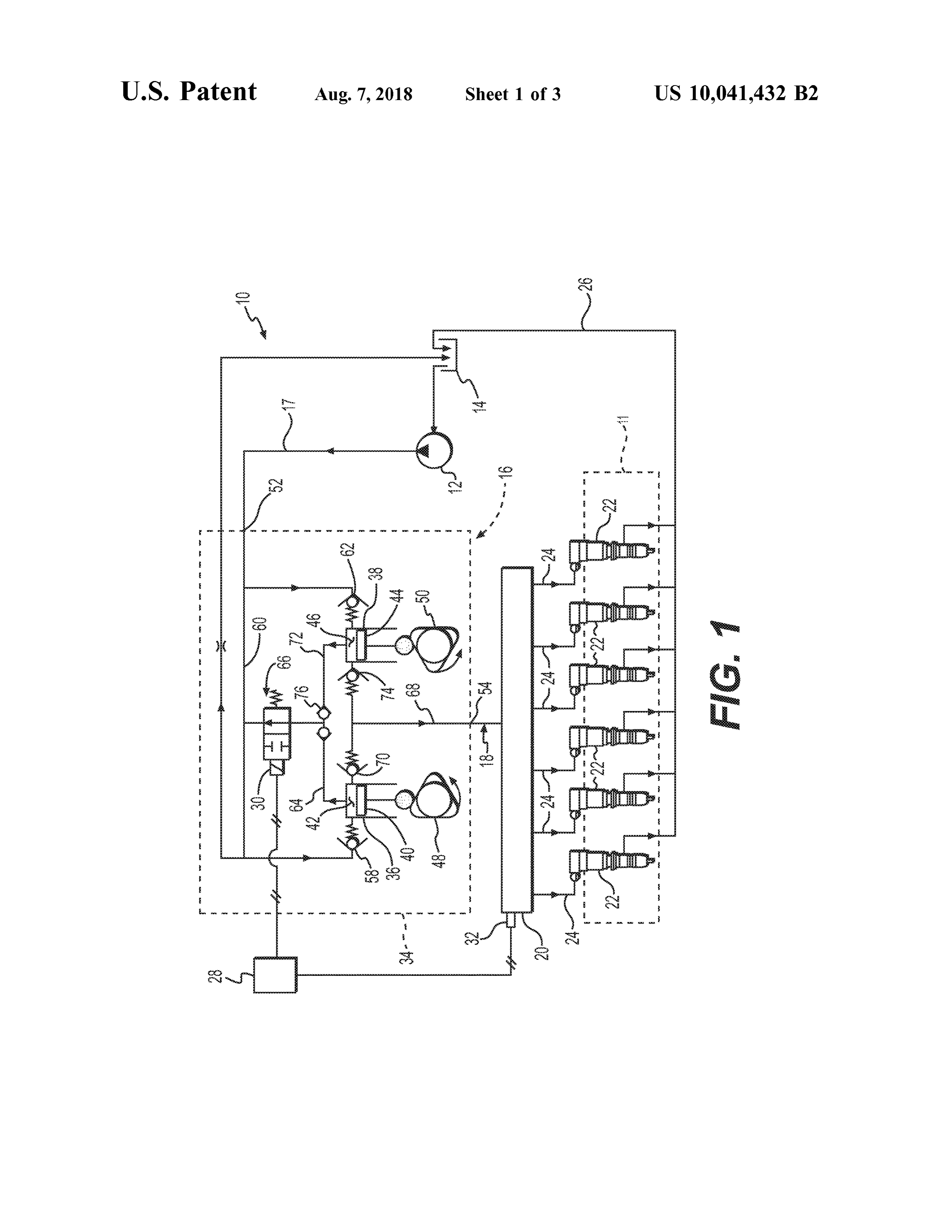
of the problems set forth above and /or other problemsof the 50 prior art . BRIEF DESCRIPTION OF THE DRAWINGS SUMMARY FIG . 1 is a diagrammatic illustration of an exemplary disclosed fuel system ;
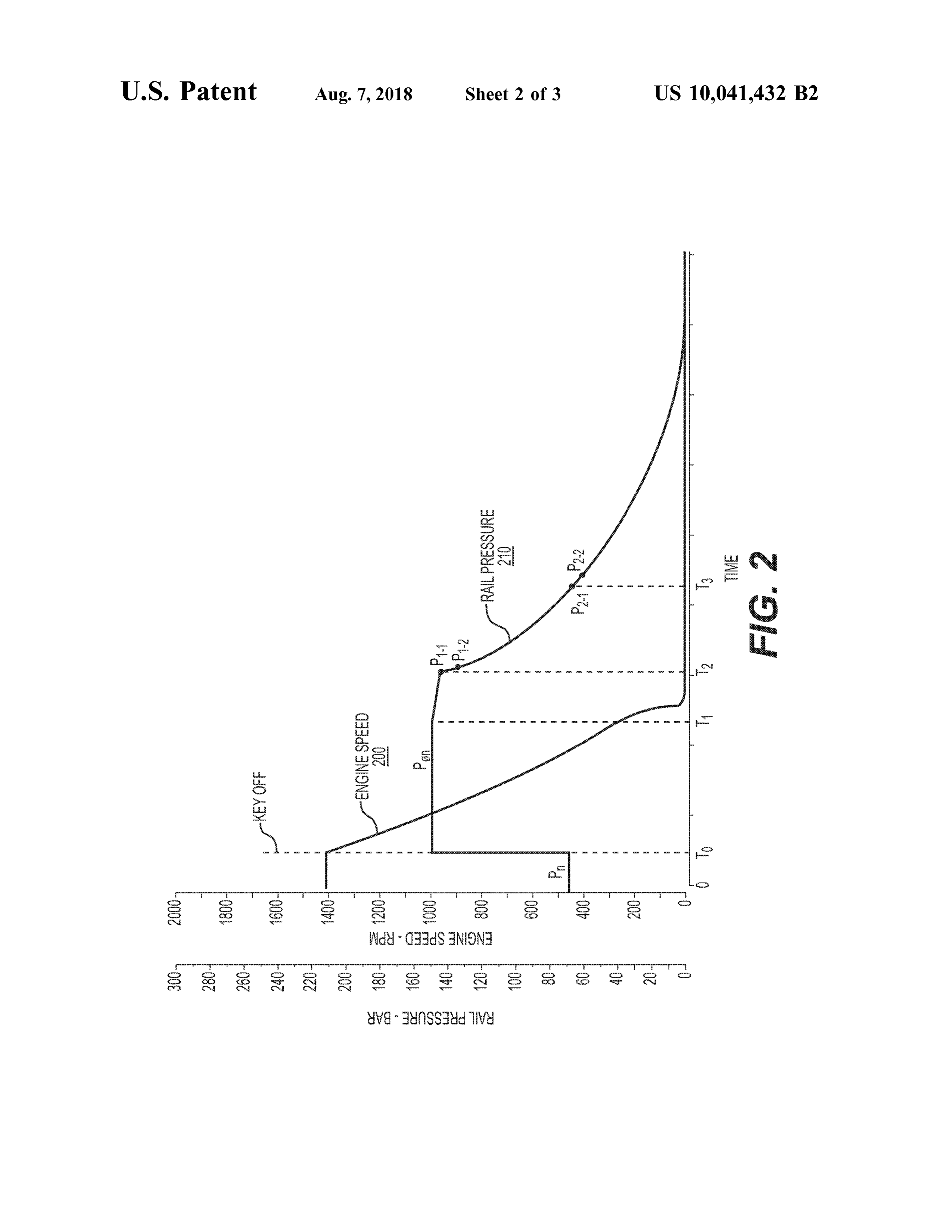
One aspect of the present disclosure is directed to a fuel 55 FIG . 2 is a trace chart showing results of an exemplary system . The fuel system may include a plurality of fuel method implemented by the fuel system of FIG . 1 ; and injectors , a common rail fluidly connected to the plurality ofFIG . 3 is a flow chart depicting the exemplary method fuel injectors, a pump configured to pressurize the common implemented by the fuel system of FIG . 1. rail, and an outlet valve associated with the pump. The fuel system may also have a sensor configured to generate a 60 DETAILED DESCRIPTION signal indicative of a pressure of fuel in the common rail, and an electronic control module in communication with the FIG . 1 illustrates an exemplary fuel system 10 for use sensor. The electronic controlmodule may be configured to with a combustion engine 11. Fuel system 10 may include, detect a zero - fueling condition , to determine a first pressure among other things a fuel transfer pump 12 that transfers decay rate of the common rail during the zero - fueling 65 fuel from a low - pressure reservoir 14 to a high -pressure condition while the pump is rotating , and to determine a pump 16 via a fluid passage 17 . High - pressure pump 16 may second pressure decay rate of the common rail during the pressurize the fuel and direct the pressurized fuel through a
Page 7
fluid passage 18 to a common rail 20 , which is in further pressure gallery 68 . It should be noted that a single outlet fluid communication with a plurality of fuel injectors 22 via valve could be used to control all flows into high -pressure individual fluid passages 24 . Fuel injectors 22 may be fluidly gallery 68 , if desired .
connected to reservoir 14 via a return passage 26 . An High - pressure pump 16 may also include a first spill electronic control module (ECM ) 28 may be in communi- 5 passage 64 selectively fluidly connecting first pumping cation with a spill control valve 30 , with a pressure sensor chamber 42 to low -pressure gallery 60, and a second spill 32 , and with each individual fuel injector 22 . As will be passage 72 selectively fluidly connecting second pumping described in more detail below , control signals may be 30chamber 46 to low -pressure gallery 60 . Spill control valve generated by ECM 28 based on feedback from sensor 32 and 10 chambers 42 ,disposed may be between first and second pumping directed to high -pressure pump 16 (e.g ., to spill control ured to selectively allow a -flow 46 and low pressure gallery 60, and config of fluid from first and second valve 30 ) for use in regulating when and how much fuel is spill passages 64 , 72 to low -pressure gallery 60 . pumped into fuel rail 20 . Similarly, control signals may be In the disclosed embodiment , only one of first and second generated by ECM 28 that are directed to fuel injectors 22 pumping chambers 42 , 46 may be fluidly connected to and used to regulate the injection timing and duration of fuel el 15 low - pressure gallery 60 at a time . That is , the fluid connec injectors 22.
High -pressure pump 16 may include a housing 34 defin gallery 60 may be established by a shuttle valvelow tion between pumping chambers 42 , 46 and -pressure 76 . Because ing one or more (e .g., first and second ) barrels 36 , 38 . first and second plungers 40 , 44 may move out of phase High -pressure pump 16 may also include a first plunger 40 relative to one another, one pumping chamber may be at slidably disposed within first barrel 36 . First barrel 36 and 20 high -pressure (pumping stroke ) when the other pumping first plunger 40 together may define a first pumping chamber chamber is at low -pressure ( intake stroke), and vice versa . 42. High - pressure pump 16 may also include a second This action may be exploited to move shuttle valve 76 back plunger 44 slidably disposed within second barrel 38 . Sec - and forth to fluidly connect either first spill passage 64 to ond barrel 38 and second plunger 44 together may define a spill control valve 30 , or second spill passage 72 to spill second pumping chamber 46 . 25 control valve 30. Thus, first and second pumping chambers First and second drivers 48, 50 may be operably con - 42 , 46 share a common spill control valve 30 . It is contem nected to first and second plungers 40 , 44 , respectively. plated , however, that separate spill control valves 30 could Drivers 48, 50 may each include means for driving first and be associated with each pumping chamber, if desired . second plungers 40 , 44 such as , for example , a cam , a ECM 28 may include all the components required to solenoid actuator, a piezo actuator, a hydraulic actuator, a 30 regulate operation of fuel system 10 such as , for example , a motor, or any other driving means known in the art. A memory , a secondary storage device , and a processor, such rotation of first driver 48 may result in a corresponding as a central processing unit. One skilled in the art will reciprocation of first plunger 40 , while a rotation of second appreciate that ECM 28 can contain additional or different driver 50 may result in a corresponding reciprocation of components . Associated with ECM 28 may be various other second plunger 44 . First and second drivers 48 , 50 may be 35 known circuits such as, for example , power supply circuitry , oriented relative to each other such that first and second signal conditioning circuitry, and solenoid driver circuitry , plungers 40 , 44 are caused to reciprocate out of phase with among others one another. First and second drivers 48 , 50 may each During control of fuel system 10 , ECM 28 may rely on include multiple (e .g ., three ) lobes such that one rotation of signals generated by pressure sensor 32 ( in addition to other a pump shaft (not shown ) connected to first and second 40 conventional engine signals ). Pressure sensor 32 may be drivers 48 , 50 results in multiple (e . g ., six ) pumping strokes . configured to continuously generate signals indicative of the It is contemplated that first and second drivers 48 , 50 may pressure of fuel inside of common rail 32 , and to direct these include any number of lobes rotated at a rate synchronized signals to ECM 28 . It should be noted that, although a single to fuel injection activity . pressure sensor 32 is shown as being located with an end of High -pressure pump 16 may include an inlet 52 that 45 common rail 20 , it is contemplated that any number of fluidly connects high -pressure pump 16 to fluid passage 17 , pressure sensors may be located anywhere within fuel and a low -pressure gallery 60 in fluid communication with system 10 ( e .g ., in communication with passage 18 , any inlet 52 and in selective communication with first and where along common rail 20 , in passage 24 , at outlet 54 , in second pumping chambers 42, 46 . A first inlet check valve passage 68 , in chambers 42 and/ or 46 , etc .). It is also 58 may be disposed between low -pressure gallery 60 and 50 contemplated that sensor 32 may alternatively sense a dif first pumping chamber 42, and configured to allow a flow of ferent or additional parameter of the fuel associated with low -pressure fluid from gallery 60 to first pumping chamber common rail 20 such as, for example, a temperature, a 42 . A second inlet check valve 62 may be disposed between viscosity , a flow rate , or another parameter known in the art. low - pressure gallery 60 and second pumping chamber 46, ECM 28 may be configured to selectively adjust the and configured to allow a flow of low - pressure fluid from 55 operation of high -pressure pump 16 in response to the gallery 60 to second pumping chamber 46 . signals received from pressure sensor 32 . That is, when the High -pressure pump 16 may also include an outlet 54 that pressure of the fuel within common rail 20 falls below a fluidly connects high -pressure pump 16 to fluid passage 18 , desired value, ECM 28 may adjust the operation of high and a high -pressure gallery 68 in selective fluid communi - pressure pump 16 to increase the pressure within common cation with first and second pumping chambers 42 , 46 and 60 rail 20 . The pressure within common rail 20 may be outlet 54 . A first outlet valve 70 may be disposed between increased , for example, by reducing an amount of fuel first pumping chamber 42 and high - pressure gallery 68 , and spilled per plunger stroke ( e .g ., by maintaining spill control configured to allow a flow of fluid from first pumping valve 30 in a closed position for a greater period of time). In chamber 42 to high -pressure gallery 68. A second outlet contrast, when the pressure of the fuel within common rail valve 74 may be disposed between second pumping cham - 65 20 rises above the desired value, ECM 28 may cause spill ber 46 and high - pressure gallery 68, and configured to allow control valve 30 to remain open for a longer period of time. a flow of fluid from second pumping chamber 46 to high - In some situations ( e.g ., during a prognostic event), ECM 28
Page 8
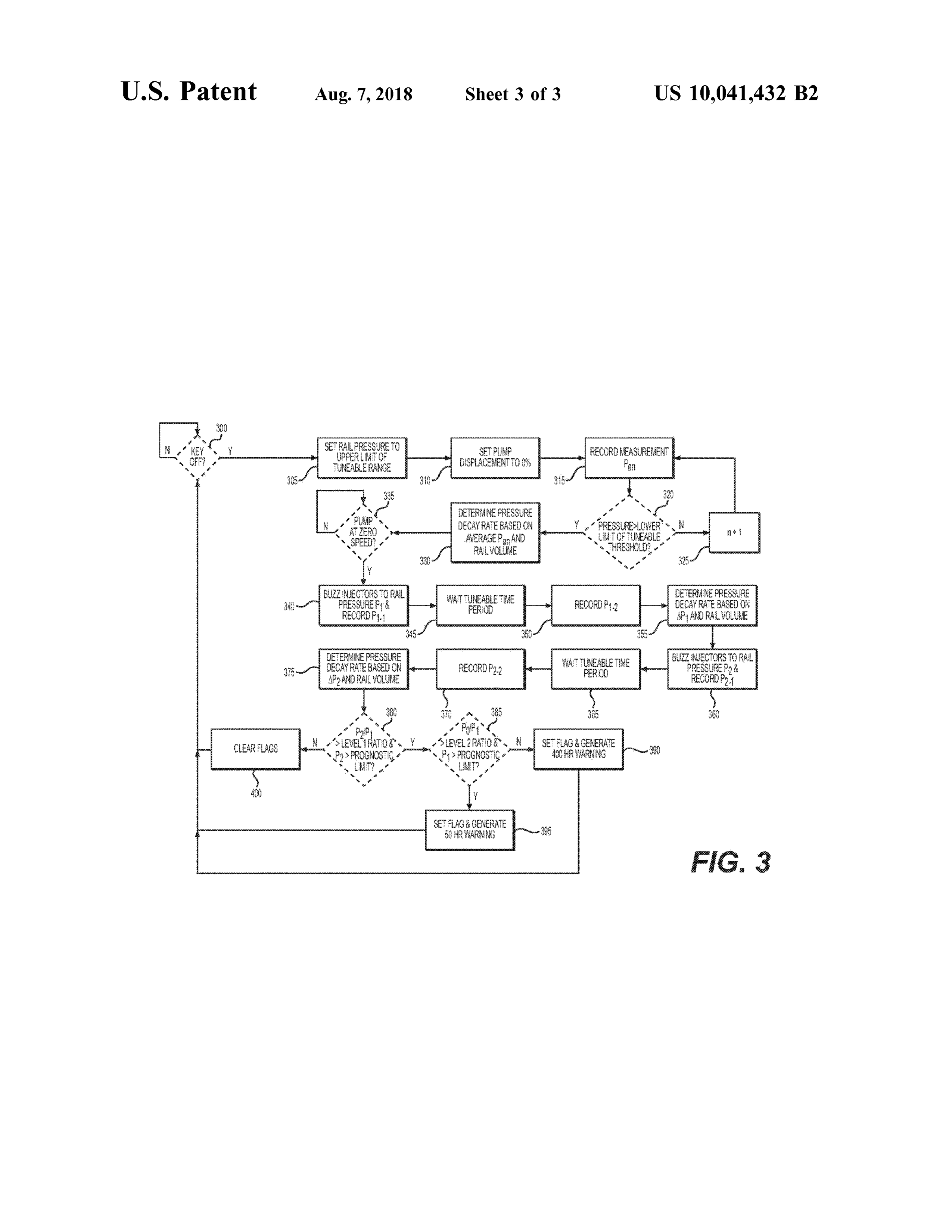
may also be configured to adjust operation of one or more of common rail 20 to the upper limit of a tuneable prognostic fuel injectors 22 (e.g., to cause fuel injectors 22 to inject range P . (step 305 ). As can be seen in trace 210 of FIG . 2 , and /or bypass a greater amount of fuel ) and thereby selec the upper limit of the prognostic range P , may be higher than tively lower a pressure within common rail 20 . the normal pressure Pn of common rail 20 . In the disclosed FIG . 2 illustrates a graph depicting an exemplary opera - 5 example of FIG . 2 , the upper limit of the prognostic range tion of fuel system 10 . The graph includes a first trace 200 Po is about 2 - 2 .5 times P , . ECM 28 may raise the pressure representative of a speed of engine 11 driving high -pressure of common rail 20 from Pn to the upper limit of the pump 16 ( e. g ., as provided by an existing engine speed prognostic range Po by , for example , causing spill control sensor — not shown ) relative to time, while a second trace valve 30 to remain closed for a longer period of time during 210 represents a pressure of common rail 20 (e.g., as 10 each pumping stroke of high -pressure pump 16 . This may provided by sensor 32 ) relative to time. As shown by first increase the effective displacement of high - pressure pump and second traces 200 , 210 , during normal operation (i.e ., 16 and thereby cause high -pressure pump 16 to supply when engine 11 is operating at about 1400 rpm ), high - pressurized fuel into common rail 20 at a greater rate , at a pressure pump 16 may be controlled ( e. g., via operation of time when injectors 22 are injecting less (if any ) fuel . spill control valve 30 ) to pressurize common rail 20 to a first 15 After completion of step 305, ECM 28 may reduce the or normal pressure level (e . g ., to about 450 bar ) P ,,. At a time effective displacement of high - pressure pump 16 to about To , when shutdown of engine 11 has been requested ( e.g., 0 % (step 310 ), and then record the pressure ofthe fuel inside when a key of engine 11 has been manually turned off ) of common rail 20 (step 315 ) . ECM 28 may repetitively to and / or commanded (e.g ., automatically by an autonomous do this until the pressure of the fuel inside common rail 20 vehicle controller — not shown ), ECM 28 may initiate a 20 falls to a lower limit of the tuneable pressure range Po . That prognostic routine . This routine is depicted in first and is , as long as a comparison performed at a step 320 indicates second traces 200 , 210 of FIG . 2 , as well as in the flowchart that the pressure measured at step 315 is not lower than the of FIG . 3 . FIGS. 2 and 3 will be described in more detail to lower limit of the pressure range P ., ECM 28 may increase further illustrate the disclosed system and its operation . a counter (n + 1 - step 325 ) , and control may return to step 25 315 to record another pressure measurement. Once the
INDUSTRIAL APPLICABILITY comparison of step 320 indicates that the pressure measured at step 315 is lower than the lower limit of the pressure range
The fuel system of the present disclosure has wide appli- P ., ECM 28 may then determine a decay rate for the pressure cation in a variety of engine types including, for example , range Po based on an average of the different recorded diesel engines, gasoline engines , and gaseous fuel-powered 30 pressures and a known volume of common rail 20 (step engines. The disclosed fuel system may be implemented into 330 ) . Steps 300 - 330 may all occur before high -pressure any engine where continuous health monitoring (e.g ., pump pump 16 has completely stopped rotating (i.e., before driv health monitoring and / or leak detection ) is important, with - ers 48 and 50 reach about zero rpm ) during engine shut out causing interruption of normal engine operation . Opera down . High -pressure pump 16 may stop rotating at a time T1 tion of fuel system 10 will now be described . 35 shown in FIG . 2 , before engine (e . g ., before an engine ECM 28 may initiate the prognostic method of FIG . 3 crankshaft — not shown ) 11 has stopped rotating.
every time that a zero -fueling condition exists . Such a Once high -pressure pump 16 stops rotating (i.e ., after condition may include any situation where essentially no time T , ), the pressure of the fuel inside of common rail 20 fuel is being injected by injectors 22 , for example, when the may decay at a greater rate . Accordingly, ECM 28 may host machine is coasting or when engine 11 is being shut 40 determine when high -pressure pump 16 has stopped rotating down . In the disclosed example, ECM 28 determines a zero (step 335 ), and then set the pressure of common rail 20 to the fueling condition by monitoring when a key (not shown) of upper limit of another prognostic range P , and record a the host machine has been manually turned to an off -position measurement of the pressure (P1-1; step 340 ). ECM 28 may (Step 300 ). It is contemplated , however, that ECM 28 may determine when high - pressure pump 16 has stopped rotating determine existence of the zero - fueling condition based 45 in any number of different ways . For example , ECM 28 may instead off of a current directed to fuel injectors 22 , a current make this determination based on a sudden change in the directed to high - pressure pump 16 , a position of an accel - pressure decay rate of common rail 20 ( e .g ., as detected via eration or deceleration pedal (not shown ), a pressure of fuel sensor 32 ). Alternatively , ECM 28 may determine that system 10 , and/ or in any other manner apparent to one high - pressure pump 16 has stopped rotating based on a skilled in the art . 50 speed of engine 11 and a known engine / pump speed rela As long as ECM 28 determines at step 300 that engine 11 tionship . In yet another embodiment, ECM 28 may deter is currently being fueled (i.e ., that the zero - fueling condition mine that high -pressure pump 16 has stopped rotating based is nonexistent- step 300 : N ) , control of fuel system 10 may on a speed of pump 16 that is directly measured via an continue normally ( i. e ., controlmay cycle through step 300) . additional speed sensor (not shown ). It is contemplated that For example, a parameter indicative of the pressure within 55 this determination could be made in other ways, if desired . common rail 20 may be monitored via sensor 32 , quantified The pressure of common rail 20 may be set to the upper limit and compared to a desired and expected common rail of prognostic range P , at a time T2 by , for example , selec pressure range . This desired and expected common rail tively “ buzzing” injectors 22 . Buzzing injectors 22 may pressure range may correspond with a pressure of fuel include selectively opening and closing injectors 22 to either within common rail 20 required for proper operation of fuel 60 inject or return fuel received from common rail 20 into injectors 22 and that results in a desired engine output ( e . g ., combustion chambers of engine 11 or back to low -pressure speed and/ or torque). Based on the comparison , ECM 28 reservoir 14 . By consuming fuel from common rail 20 at a may selectively control movement of spill control valve 30 timewhen fuel is not being supplied to common rail 20, the and/ or operation of injectors 22 to raise or lower the fuel pressure within common rail 20 will be caused to drop pressure inside of common rail 20 . 65 during completion of step 340 .
Once ECM 28 determines that the zero - fueling condition After ECM 28 records pressure measurement P . 1 , ECM exists (step 300: Y ), ECM 28 may set the fuel pressure of 28 may be configured to wait a tuneable time period ( step
Page 9
345 ), and then record another pressure measurement P1-2 plary only , with a true scope of the disclosure being indi (Step 350 ). ECM 28 may then determine a pressure decay cated by the following claims and their equivalents. rate for the prognostic range P , based on AP , and the known What is claimed is :
volume of common rail 20 (step 355 ) . 1 . A fuel system for an engine , comprising : After completion of step 355 , ECM 28 may again set the 5 a plurality of fuel injectors;
pressure of common rail 20 to the upper limit of yet another a common rail fluidly connected to the plurality of fuel prognostic range P2, and record a measurement of the injectors ;
pressure (P2-1; step 360 ) at a time Tz. The pressure of a pump configured to pressurize the common rail; common rail 20 may be set to the upper limit of the an outlet valve associated with the pump; prognostic range P , in the same manner described above 10 a sensor configured to generate a signal indicative of a (e. g., by buzzing injectors 22 ), in regard to step 340. pressure of fuel in the common rail; and Thereafter, ECM 28 may wait another tuneable time period an electronic control module in communication with the ( step 365 ), and then record another pressure measurement sensor and configured to : P2-2 ( step 370 ). ECM 28 may then determine a pressure detect a zero -fueling condition ; decay rate for the prognostic range P2based on AP2 and the 15 determine a first pressure decay rate of the common rail known volume of common rail 20 (Step 375 ). during the zero -fueling condition while the pump is ECM 28 may be configured to then determine a health rotating;
( e. g ., predict a remaining useful life ) ofhigh -pressure pump determine a second pressure decay rate of the common 16 based on the pressure decay rates Po , P1, and P ,. In rail during the zero - fueling condition after the pump particular, ECM 28 may compare a ratio of P2/P , to a level-1 20 has stopped rotating ; and ratio , and P , to a prognostic limit ( step 380 ) . When the ratio selectively generate a diagnostic flag associated with of P ,/ P , is greater than the level- 1 ratio and P , is greater than wear of the outlet valve based on the first and second the prognostic limit (step 380 : Y ), ECM 28 may then pressure decay rates. compare a ratio of PP, to a level- 2 ratio , and P , to a 2 . The fuel system of claim 1, wherein the electronic prognostic limit ( step 385 ). When the ratio of P /P , is less 25 controlmodule is further configured to :
than the level- 2 ratio and /or P , is less than the prognostic determine a third pressure decay rate of the common rail limit , ECM 28 may set an internal diagnostic flag and also during the zero -fueling condition after the pump has generate an early -hour warning indicating that high - pressure stopped rotating; and pump 16 (i. e ., that outlet valve 70 and/ or 74 of pump 16 ) is selectively generate the diagnostic flag associated with reaching a wear threshold that requires servicing ( Step 390 ). 30 wear of the outlet valve based on the first, second, and In one example , the early -hour warning may be associated third pressure decay rates. with about 400 hrs . until failure . However, when the ratio of 3 . The fuel system of claim 2 , wherein the electronic PD/ P , is greater than the level- 2 ratio and P , is greater than control module is configured to selectively generate : the prognostic limit, ECM 28 may set an internal diagnostic a first diagnostic flag associated with an early -hour warn flag and also generate a late -hour warning indicating that 35 ing ; and high -pressure pump 16 is at the threshold that requires a second diagnostic flag associated with a late -hourwarn servicing (Step 395 ). In one example , the late -hour warning ing.
may be associated with about 50 hrs . until failure . The 4 . The fuel system of claim 3 , wherein : relationships between the above-described ratios and the the early -hour warning is associated with about 400 hrs. hours until failure of high -pressure pump 16 may be deter - 40 until failure of the pump ; and mined based on empirical data . Returning to step 380 , when the late -hourwarning is associated with about 50 hrs. until the ratio of P2P , is less than the level- 1 ratio or P , is less failure of the pump .
than the prognostic limit , all previously set diagnostic flags 5 . The fuel system of claim 3, wherein : may be cleared . Controlmay return from steps 390, 395 , and the 111first pressure decay rate is associated with a pressure the 400 to step 300 . range that is higher than pressure ranges associated Fuel system 10 may provide improved prognostic func with the second and third pressure decay rates, and tionality . In particular,because fuel system 10 may check for the pressure range associated with the second pressure pump leakage (i. e ., leakage at outlet valve 70 and / or 74 ) decay rate is higher than the pressure range associated every time engine 11 experiences a zero - fueling condition , with the third pressure decay rate .
the health of high -pressure pump 16 may be continuously 50 6 . The fuel system of claim 5 , wherein the electronic determined and immediately accommodated . In addition , control module is configured to generate the first diagnostic fuel system 10 may perform this function without causing flag when a ratio of the third pressure decay rate to the significant interruption of engine operation . Further, because second pressure decay rate is greater than a level- 1 ratio , the ECM 28 may provide both an early -hour warning and a third pressure decay rate is higher than a prognostic limit, late -hour warning , the owner /operator of engine 11 may 55 and a ratio of the first pressure decay rate to the second have flexibility regarding where and when to make any pressure decay rate is less than a level- 2 ratio . necessary repairs . Further, the disclosed warningsmay allow 7 . The fuel system of claim 6 , wherein the electronic for parts to be ordered and / or for the service to be scheduled control module is configured to generate the second diag in advance of their need . This may help to reduce downtime nostic flag when the ratio of the third pressure decay rate to caused by the service . 60 the second pressure decay rate is greater than the level - 1 It will be apparent to those skilled in the art that various ratio , the third pressure decay rate is higher than the prog modifications and variations can be made to the fuel system nostic limit, and the ratio of the first pressure decay rate to of the present disclosure without departing from the scope of the second pressure decay rate is greater than the level- 2 the disclosure . Other embodiments will be apparent to those ratio .
skilled in the art from consideration of the specification and 65 8 . The fuel system of claim 5 , wherein the first pressure practice of the fuel system disclosed herein . It is intended decay rate is associated with a pressure range that is about that the specification and examples be considered as exem - 2 to 2 . 5 times a normal operating pressure .
Page 10
9. The fuel system of claim 5 , wherein the electronic the ratio of the first pressure decay rate to the control module is configured to cause the pump to raise the second pressure decay rate is greater than the pressure of the common rail to a first range prior to deter level- 2 ratio .
mining the first pressure decay rate . 14 . A method of prognosticating health of a fuel system , 10 . The fuel system of claim 9 . wherein the electronic 5 the method comprising :
control module is configured to buzz the injectors to lower detecting a zero - fueling condition ; determining a first pressure decay rate of a common rail the pressure of the common rail prior to determining the during the zero - fueling condition while an associated second pressure decay rate and again prior to determining pump is rotating ;
the third pressure decay rate . determining a second pressure decay rate of the common 11. The fuel system of claim 9, wherein the electronic 10 rail during the zero - fueling condition after the pump control module is configured to determine the first pressure has stopped rotating; and decay rate based on an average of multiple pressure mea selectively generating a diagnostic flag corresponding to surements taken while the pump is still rotating during the wear of an outlet valve associated with the pump based zero - fueling condition . on the first and second pressure decay rates . 12 . The fuel system of claim 11 , wherein the electronic 15 ing15a .third
The method of claim 14 , further including determin pressure decay rate of the common rail during the control module is configured to determine each of the second and third pressure decay rates based on two pressure zero - fueling condition after the pump has stopped rotating, measurements spaced apart from each other by a tuneable wherein selectively generating the diagnostic flag includes selectively generating the diagnostic flag based on the first, time period .
13 . A fuel system , comprising: 20 second , and third pressure decay rates . a plurality of fuel injectors ; 16 . The method of claim 15 , wherein selectively gener fuel ali a common rail fluidly connected to the plurality of fuel ating the diagnostic flag includes generating: injectors ; a first diagnostic flag associated with an early -hour warn a pump configured to pressurize the common rail; 25 ing ; and an outlet valve associated with the pump; a second diagnostic flag associated with a late -hourwarn a sensor configured to generate a signal indicative of a ing .
pressure of fuel in the common rail; and 17 . The method of claim 16 , wherein : an electronic control module in communication with the the early -hour warning is associated with about 400 hrs . sensor and configured to : until failure of the pump ; and 30 the late -hour warning is associated with about 50 hrs. until detect a zero -fueling condition ; failure of the pump.
determine a first pressure decay rate of the common rail during the zero - fueling condition while the pump is 18 . The method of claim 17 , wherein : rotating; the first pressure decay rate is associated with a pressure determine a second pressure decay rate of the common 35 range that is higher than pressure ranges associated rail during the zero - fueling condition after the pump with the second and third pressure decay rates ; and has stopped rotating in association with a first pres the pressure range associated with the second pressure sure range; decay rate is higher than the pressure range associated determine a third pressure decay rate of the common with the third pressure decay rate . 19 . The method of claim 18 , wherein generating the first rail during the zero -fueling condition after the pump 40O diagnostic has stopped rotating in association with a second flag includes generating the first diagnostic flag pressure range that is lower than the first; and when a ratio of the third pressure decay rate to the second selectively generate: pressure decay rate is greater than a level- 1 ratio , the third an early -hour flag associated with wear of the outlet ratio of thedecay pressure rate is higher than a prognostic limit, and a first pressure decay rate to the second pressure valve when a ratio of the third pressure decay rate 45 to the second pressure decay rate is greater than a decay rate is less than a level- 2 ratio . 20 . The method of claim 19 , wherein generating the level- 1 ratio , the third pressure decay rate is higher second diagnostic flag includes generating the second diag than a prognostic limit, and a ratio of the first pressure decay rate to the second pressure decay nostic flag when the ratio of the third pressure decay rate to rate is less than a level- 2 ratio ; and the second pressure decay rate is greater than the level - 1 a late-hour diagnostic flag associated with wear of ratio , the third pressure decay rate is higher than the prog the outlet valve when the ratio of the third pressure nostic limit , and the ratio of the first pressure decay rate to decay rate to the second pressure decay rate is the second pressure decay rate is greater than the level- 2 greater than the level- 1 ratio , the third pressure ratio .
decay rate is higher than the prognostic limit, and * * * * *
Provenance
- Collection
- Cited prior art
- Original PDF
- patentimages.storage.googleapis.com →
- Filed
- 2017-01-09
- Pages
- 10
- Method
- pdftotext (the PDF's own text layer) + pdftoppm 300dpi page scans
- Source
- Google Patents bibliographic record
- Granted
- 2018-08-07
- Inventors
- Daniel Reese Puckett; Bradley Scott Bashore; Michael Edward Sattler; Michael Scott MARCHIONDA; Sasidhar Rayasam; Kranti Kumar Nellutla; Caterpillar Inc
- Transcribed from
- patentimages.storage.googleapis.com →