patent · US4807584
Fuel tank heating system
28 February 1989
Page 1 — bibliographic record
United States Patent (19) 11 Patent Number: 4,807,584 Davis (45) Date of Patent: Feb. 28, 1989 54 FUELTANK HEATING SYSTEM 4,372,280 2/1983 Adams ................................ 123/557
(75) Inventor: Leland L. Davis, Saline, Mich. 4411,240 10/1985 Kravetz . (73) Assignee: Davco Manufacturing Corp., Ann 4,489,708 12/1984 Yamamoto et al. ............ 123/557 X Arbor, Mich. 4,509,464 4/1985 Hansen ............. ... 23/557 4,515,135 5/1985 Glass ..... ... 123/557 21 Appl. No.: 120,185 4,516,556 5/1985 Meyer ............................. 123/552 X 22) Filed: Nov. 9, 1987 FOREIGN PATENT DOCUMENTS
Related U.S. Application Data (63) Continuation of Ser. No. 676,869, Nov. 30, 1984, aban Primary Examiner-Tony M. Argenbright doned. Attorney, Agent, or Firm-Harness, Dickey & Pierce 51) Int. Cl* ...................... F02M 31/12; F02M 31/14 57 ABSTRACT 52) U.S. C. ..................................... 123/557; 123/549 An improved fuel heating system particularly adapted 58) Field of Search ............... 123/557, 549, 558, 522, for fuel oil combustion machines such as diesel powered 123/523 motor vehicles and stationary generating plants is dis (56) References Cited closed. The appratuses include a fuel processing device which is integral or separate from a fuel tank which
1,382,995 6/1921 Lucke.................................. 123/557 device. The apparatuses further include a mechanism 1,819,474 8/1931 Meyer ......... ow was .......... 123/557 for heating fuel within the fuel tank in order to warm it 2,437,453 3/1948 Belgau . to a flowable condition so that it can be transmitted to 2,747,555 5/1956 Brunner . the fuel processor for further heating. Several embodi 2,882,882 4/1959 Pantano ............................... 123/523 ments are described wherein the fuel processor and
3,354,872 11/1967 Gratzmuller . main fuel reservoir are within the same vessel and sepa 3,713,429 1/1973 Dwyre ................................ 123/552 rated only by a fluidtight wall. In another embodiment, 3,768,730 10/1973 Campbell. a fuel processor unit is physically separated from the 3,962,999 6/1976 Rehm . fuel tank. Various means are described for communicat 3,989,019 11/1976 Brandt et al. . ing heat within the fuel processor to the main fuel reser 4,003,356 1/1977 Naylor. voir including conduits conducting engine coolant and 4,044,742 8/1977 Linder ................................. 123/557 ror or plate type heat conductors. This invention pro 4,237,850 12/1980 Connor et al. . vides fuel heating systems which are capable of quickly
4,312,317 l/1982 Jewett ................................. 123/552 supplying warmed fuel to a fuel oil fired device and 4,323,046 4/1982 Barber ................................. 123/557 further provides such heating in a highly efficient man 4,338,907 7/1982 Lindbeck ............................ 123/557 e.
4,370,970 2/1983 Kunz ................................... 123/557 7 Claims, 2 Drawing Sheets
ass,
Sna Nrazzzzzzzzzzzzzzzzz as
Page 2
Drawing sheet — no readable text.
Page 3
Drawing sheet — no readable text.
Page 4
a fuel tank prior to its introduction into the remainder of
FUELTANK HEATING SYSTEM the fuel delivery circuit. It is a further object of this invention to accomplish such fuel heating using a mini
This is a continuation of U.S. patent application Ser. mal power input requirement. Additional objects of the No. 676,869, filed Nov. 30, 1984 and entitled fuel tank 5 invention are to provide such fuel heating employing a heating system, now abandoned. minimum of components and providing a system simple BACKGROUND AND SUMMARY OF THE in configuration and operation.
INVENTION The above objects of this invention are achieved by employing a fuel processor device which acts as a small
This invention relates to a fuel heating system and 10 capacity fuel reservoir which provides warmed fuel for particularly, to a system for heating fuel oil within a fuel initial operation, and a larger capacity main fuel reser tank before it is conducted into a fuel delivery circuit. voir which holds the bulk of the stored fuel. The larger Diesel engine powered machines such as motor vehi capacity main fuel reservoir includes heating means cles, stationary generating plants, and other fuel oil associated with the fuel processor to provide a sufficient combustion devices are often operated in environmental 15 flow rate of warmed fuel to sustain continued operation conditions wherein the fuel oil and fuel delivery circuit of the associated fuel oil fired device. High overall are subjected to cold ambient temperatures. At suffi thermal efficiency is provided by heating a very small ciently low temperatures, fuel oils become viscous, and quantity of fuel oil for initial start-up and by providing develop paraffin or wax particles. These fuels have a steady state energy input level into the main fuel reser characteristic temperatures at which they become 20 voir which warms fuel to provide a flow rate of "cloudy" due to the pressure of dispensed wax crystals warmed fuel related to the fuel consumption rate of the and at which they "freeze' or become a semi-solid fuel consuming device. No attempt need be made in mass, referred to as their cloud and pour points, respec accordance with this invention to maintain the entire tively. Often fuel oil in use is exposed to these critical contents of the main fuel reservoir in a wax-free state, temperatures. Some diesel engine fuels have a cloud 25 even while the fuel consuming device is operating. point of 20 degrees Fahrenheit and a pour point of 0 Additional benefits and advantages of the present degrees Fahrenheit. Additionally, water which invari invention will become apparent to those skilled in the ably is mixed with the fuel oil can freeze, forming ice art to which this invention relates from the subsequent particles. Such conditions may severely restrict fuel description of the preferred embodiments and the ap flow within the fuel delivery circuit, leading to reduced 30 pended claims, taken in conjunction with the accompa power output or complete inoperability of the associ nying drawings.
ated fuel consuming device. Such problems obviously BRIEF DESCRIPTION OF THE DRAWINGS occur when the fuel reduces the point of solidification.
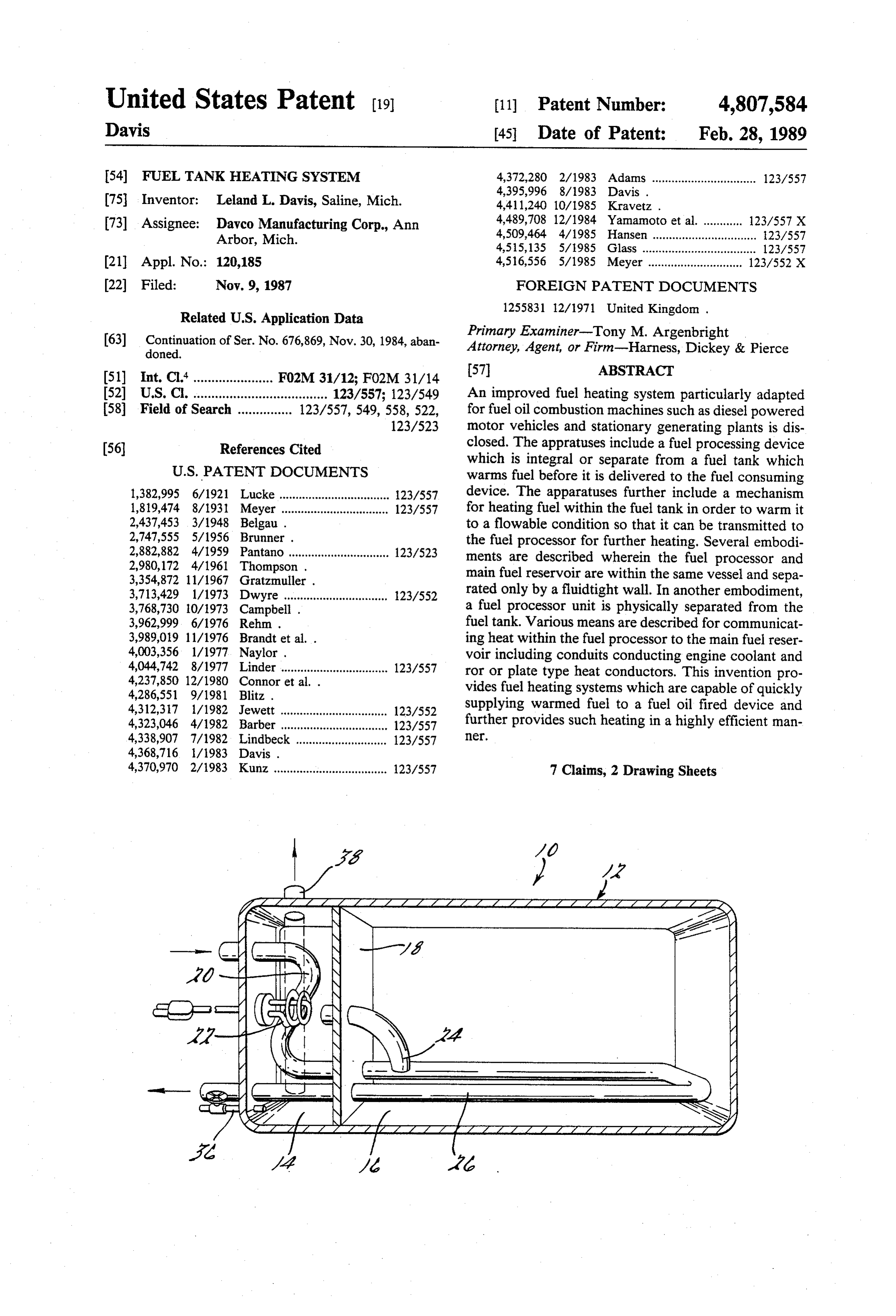
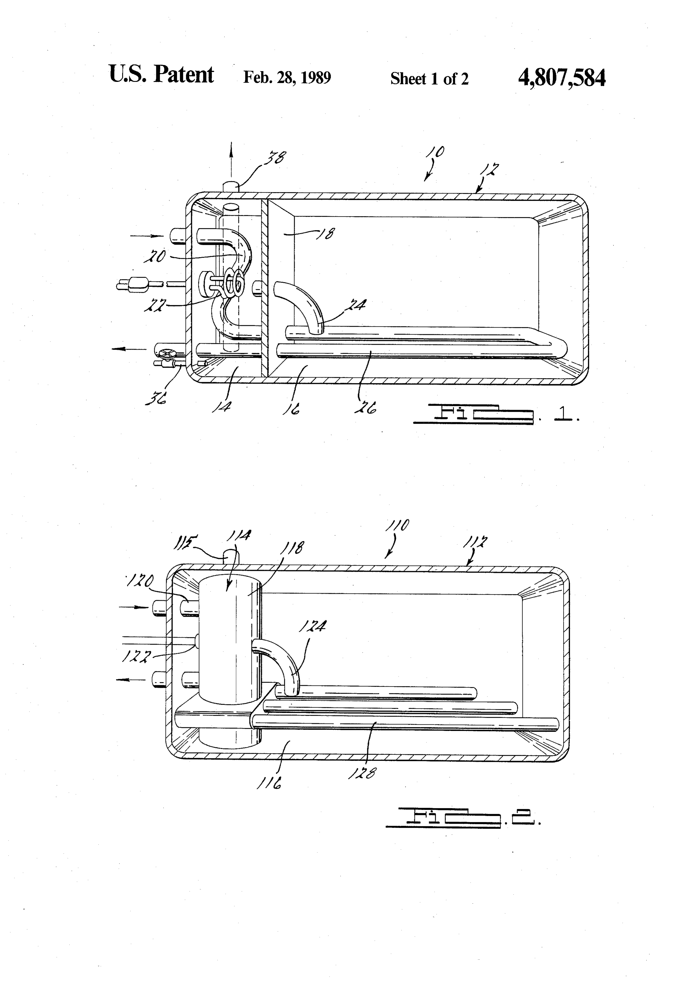
Cloudy fuel may also lead to fuel flow restrictions when FIG. 1 is a cross-sectional view of a fuel heating the suspended wax particles accumulate in filter ele 35 system according to a first embodiment of this invention ments and at other points in the fuel system. One which employs a separated fuel tank having a fuel pro method of preventing this condition is to maintain the cessing section and a main fuel reservoir section, and fuel temperature above its cloud and pour points. This having a heated fluid conducting conduit disposed in approach, however, is not always possible since ade both fuel tank sections;
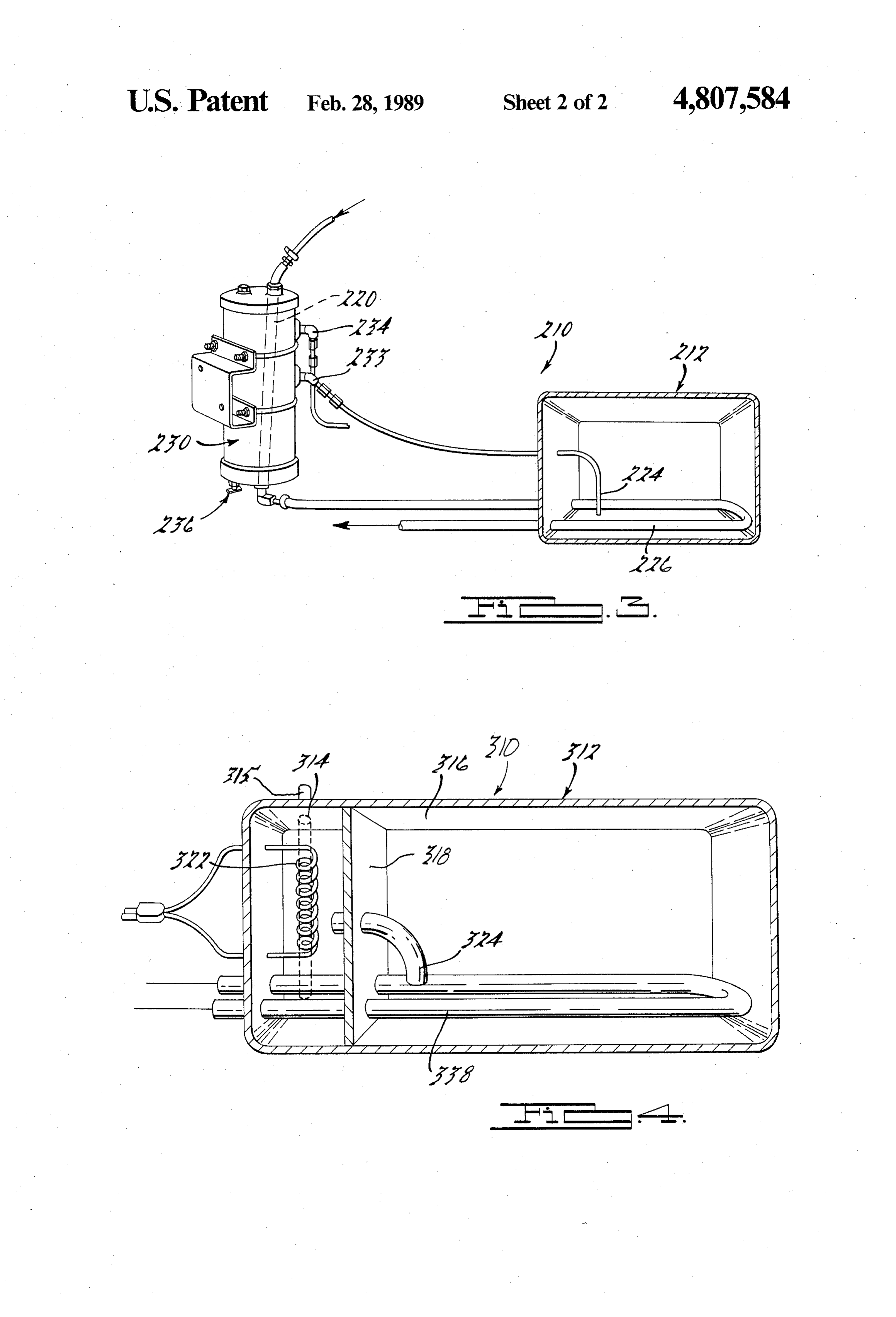
quate heat or power may not be available during stor FIG. 2 is a cross-sectional view of a fuel heating age periods, or while the associated fuel oil fired device system according to a second embodiment of this inven is not operating. tion wherein heat conducting members are placed in In order to address such problems, many users of fuel thermal communication with the fuel processing section oil combustion devices such as diesel engines provide of a separated fuel tank which conducts heat into the fuel processing devices within the fuel delivery circuit. 45 main fuel reservoir section of the tank; A number of such devices are described by my previ FIG. 3 is a pictorial view of a fuel processor and a ously issued U.S. Pat. Nos.: 4,368,716; 4,428,351; cross-sectional view of a fuel tank of a third embodi 4,395,996; 4,421,090; and my currently pending patent ment of this invention wherein the fuel processor and applications; Ser. Nos.: 463,041, filed Feb. 1, 1983; fuel tank components are physically separated and in 573,292, filed Jan. 23, 1984; and 653,854, filed Sept. 24, 50 clude means for conducting a heated fluid into a conduit 1984. Many of the fuel processors and fuel heating appa within the fuel tank for heating fuel therein; and ratuses described by the preceding patents and patent FIG. 4 is a cross-sectional view of a fuel heating applications further provide water separation and par system according to a fourth embodiment of this inven ticulate filtration functions. Although these devices are tion wherein a pair of electrically energized heating entirely satisfactory in heating fuel drawn from a fuel 55 devices are employed.
reservoir in sufficiently cold ambient temperatures or DETAILED DESCRIPTION OF THE when prolonged cold soaking occurs, it may be difficult or impossible to draw fuel from the fuel tank. In such INVENTION conditions, the fuel oil within the fuel tank can become A fuel heating system according to a first embodi an essentially immovable mass of completely waxed ment of this invention is shown in FIG. 1 and is gener fuel. In addressing such problems, designers of fuel ally designated there by reference character 10. System heating systems in the past have attempted to overcome 10 is particularly adapted for use in a fuel supply system such difficulties by supplying a sufficient level of heat for a diesel engine powered device such as a motor energy to the fuel tank to melt the entire contents. How vehicle or a power generating plant. System 10, and ever, such approaches require such extremely high 65 those described hereinafter, however, may be used in power requirements as to be inefficient or prohibitive. conjunction with any type of fuel combustion operated In view of the above, it is an object of this invention device, including turbine engines, furnaces, etc. Fuel to provide an apparatus which acts to warm fuel within heating system 10 includes fuel tank 12 which is divided
Page 5
into two sections, fuel processing section 14 and main processing section 14 becomes warmed. Heated fluid fuel reservoir section 16, which are physically separated flow within conduit 26 causes localized warming of the by wall 18. Fuel processing section 14 includes inter fuel within main fuel reservoir section 16. This localized nally disposed conduit 20 which conducts aheated fluid warming provides fuel in a flowable state adjacent the such as engine coolant within fuel processing section 14 5 inlet of fuel pickup tube 24. As previously stated, it is and is in heat exchange relationship with the fuel not necessary to completely warm the entire contents of therein, thereby warming the fuel. Additionally, fuel fuel storage section 16. In fact, it has been found that the processing section 14 may include electric immersion formation of a continuous surface of paraffin on the heater 22 which may be employed to maintain the tem interior surfaces of fuel storage section 16 actually en perature of the fuel within the fuel processor section 14 10 hances the efficiency of the fuel warming effect pro at a level above its cloud point, thereby maintaining the vided by conduit section 26, since it acts as an efficient associated device in a state of constant readiness. Elec insulating layer. Further, this insulating layer prevents tric immersion heater 22 may also be energized a short excessive heat loss from fuel processing section 14 when time period before attempted start-up of the associated electric heater 22 is energized. Efficiency of the system fuel oil fired apparatus, thereby warming a small quan 15 is provided since the amount of fuel initially heated tity of fuel for initial operation. Wall 18 may be formed within fuel processing section 14 is only that quantity from any suitable material, for example, sheet metal, necessary to sufficiently warm the engine until a hot and acts to separate the fluids within fuel tank 12 into fluid for fuel warming becomes available. Fuel within two sections. Fuel outlet conduit 38, disposed in fuel main fuel reservoir section 16 is heated at the rate at processing section 14, serves to conduct fuel to the 20 which it is being consumed by the associated engine. remaining branches of the fuel delivery circuit or to a Control over the system may be provided by employing particulate filter mounted within or to fuel tank 10. The a temperature sensitive element which modulates en use of such particulate filters mounted directly to a fuel ergy supplied to electric heater 22. Similarly, the flow tank having a fuel heating section is disclosed in my of fluid within conduits 20 and 26 may be controlled to issued U.S. Pat. No. 4,395,996 which is hereby incorpo 25 prevent fuel overheating.
rated by reference. Drain valve 36 is optionally pro In those applications where electric heater 22 is not vided to permit the periodic removal of water or other employed, other means are preferably employed to impurities which collect in the lower portion of section provide a quantity of warmed fuel required to support 14. internal combustion. Thereafter, when a warmed fluid In accordance with this embodiment, conduit 20 is 30 becomes available for transmission within conduits 20 elongated to have a portion thereof, identified by refer and 26, the fuel becomes warmed in a progressive man ence number 26, which extends into a lower portion of ner, to above its pour point in main fuel reservoir sec main fuel reservoir section 16. Conduit portion 26 pref tion 16 to a more elevated temperature (preferably erably is shaped to provide an optimum or adequate above the fuel's cloud point) in fuel processing section heat transfer surface and is positioned immediately 35 14.
above a portion of the floor of tank 12. Engine coolant A second embodiment according to this invention is or another heated fluid such as oil, exhaust gases, etc. is shown in FIG. 2. Fuel heating system 110, like the first preferably conducted within conduit 20 such that it is embodiment, includes fuel tank 112, divided into two first conducted into section 14 and thereafter into sec sections; fuel processing section 114 and main fuel reser tion 16. This direction of flow insures that the greatest 40 voir section 116. This embodiment varies from the first, amount of heat available for fuel warming is provided in however, in that wall 118 forms a fully enclosed vessel fuel processor section 14. Fuel pickup tube 24 forms a which is surrounded by fuel within section 116. Dis fuel communication path between sections 14 and 16. posed within processing section 114 is a heat source Fuel pickup tube 24 has an inlet which is located in comprising, for example, conduit 120 which conducts a close proximity with conduit 26 within fuel storage heated fluid such as engine coolant within that section. section 16 and is preferably positioned between the legs Electrical immersion heater 122 may also be installed of conduit 26. Further, fuel pickup tube 24 is preferably within fuel processing section 116 as an additional or located slightly above conduit 26. This relationship of exclusive heat source and may be continuously ener fuel pickup tube 24 with respect to conduit 26 provides gized or energized a short period of time prior to engine a location desirable from a heat transfer view point to 50 start-up. Outlet conduit 115 allows fuel to be removed provide warmed fuel to fuel processing section 14. from fuel processing section 114. This embodiment In order to maximize the useful fuel capacity of fuel varies principally from the first in that conduit 120 is not tank 12, it may be desirable to locate conduit 26 and fuel extended to form a section 26 within main fuel reservoir pickup tube 28 in a locally depressed sump section of section 116. Instead, other means are employed to con the tank. The tank shapes shown herein are provided 55 duct heat into section 116 to provide initial warming of for illustrative purposes only. fuel within that section. For this embodiment, heat from In operation, when used in a diesel engine fuel deliv section 114 is conducted into main fuel reservoir section ery system, energy is applied to electric heater 22 con 116 using heat radiating rods or tubes 128 which are stantly or during a predetermined period of time prior attached to wall 118 in a manner permitting conductive to engine start-up. This energy input warms a small heat transfer between these components. Rods 128 are volume of fuel within fuel processing section 14. When preferably made from a metal exhibiting high heat con liquified fuel is available, it is transmitted from section duction properties such as copper or aluminum. Heat is 14 to the associated diesel engine or other fuel consum transferred through conduction to rods 128 and is there ing device. Upon engine warmup, heated engine cool after dissipated to fuel surrounding the rods. Like the ant, lubricating oil, exhaust gases or an intermediate 65 first embodiment, fuel pickup tube 124 is employed heat exchange fluid become available for transmission which communicates fuel processing section 114 with into conduits 20 and 26. When the circulated fluid fuel storage section 116. The orientation of pickup tube reaches a suitable temperature, the entire volume of fuel 124 is also like that previously described, i.e. it is placed
Page 6
in close proximity with the heat source and preferably fuel pickup tube 324 is heated to a point where it can be vertically above it, thereby taking advantage of heat drawn into section 114 in a manner like that according transfer principles to provide efficient preheating of to the second embodiment shown in FIG. 2. The prox fuel. imity of fuel pickup tube with heater 338 is substantially A number of variations of the second embodiment of 5 like that previously described for the previous embodi fuel heating system 110 are also well within the scope of ments. An automatic control system like that described this invention. For example, a solid plate could be used previously is needed for the apparatus shown in FIG. 4. in place of rods or tubes 128. Additionally, so-called Such control could be achieved by employing a sepa “heat pipes' could be used which are tubular members rate temperature sensor or by employing a self limiting filled with a two-phase heat transport media. These 10 device for heaters 322 and 338 such as those made from devices exhibit exceptional heat transfer capabilities positive temperature coefficient (PTC) materials. since they approach maintaining their entire surface at a While the above description constitutes the preferred uniform temperature despite locallized thermal load embodiments of the present invention, it will be appre ings. The use of heat radiating rods or pipes or other ciated that the invention is susceptible to modification, heat conduction means described in conjunction with 15 variation and change without departing from the proper this embodiment could also be employed with the pla scope and fair meaning of the accompanying claims. nar shaped wall 18 of the first embodiment. What is claimed is:
A third embodiment of a fuel heating system accord 1. A fuel supply system of a combusion device for ing to this invention is shown with reference to FIG. 3 heating fuel, comprising:
and is designated there by reference character 210. This 2O a fuel tank, embodiment differs from the two previously described a partition dividing said fuel tank into a fuel process in that the fuel processing apparatus is physically sepa ing section and a fuel reservoir section, said fuel rated from fuel tank 212. As shown in FIG. 3, a separate processing section adapted to retain a volume of fuel processor 230 is employed. This device may be any fuel which is substantially less than the fuel volume high-performance fuel processor which provides fuel capacity of said fuel reservoir section, heating such as that described by my issued U.S. Pat. first fuel heating means disposed in said fuel process No. 4,368,716. Fuel processor 230 includes an internally ing section and confined to said fuel processing disposed heated fluid conducting conduit 220, and fuel section for heating fuel within said fuel processing inlet and outlet 233 and 234, respectively. Fuel proces section for providing heated fuel for initial opera sor 230 may also include an auxiliary electric heater tion of the combustion device, (not shown) and may further include a manually or second fuel heating means for heating fuel within automatically actuated drain valve 236. Another con both said fuel processor section and said fuel reser duit 226 is disposed within fuel tank 212 in a fashion voir section for providing heated fuel for sustained similar to that of the first embodiment. Similarly, fuel operation of the combustion device, said first and pickup tube 224 is provided and oriented as previously second heating means being independently opera described. Conduits are provided which communicate ble and controllable, and fuel pickup tube 224 with fuel processor 230 and con conduit means for transferring fuel from said fuel duit 220 with conduit 226. Otherwise, this device per reservoir section and into said fuel processing sec forms precisely like the first embodiment, in that a tion and for transferring fuel out of said fuel pro heated fluid, such as engine coolant, is conducted into cessing section, said conduit means including a fuel the fuel processor 230 and thereafter into conduit 226 to 0 pickup tube disposed in said fuel reservoir section provide localized warming of fuel in main fuel reservoir for conducting fuel out of said fuel reservoir sec section 216. tion from a location in close proximity with said A fourth embodiment of a fuel heating system ac second fuel heating means.
cording to this invention is illustrated in FIG. 4. This 2. A fuel supply system according to claim 1 wherein embodiment is similar to the first two in that fuel tank 45 said first fuel heating means comprises an electrical 312 is divided into two sections, fuel processing section immersion heater disposed in said fuel processing sec 314 and main fuel reservoir section 316 by wall 318. For tion.
this embodiment, conduit 20 is eliminated and section 3. A fuel supply system according to claim 1 wherein 314 is heated exclusively by electrical immersion heater said second fuel heating means comprises an electrical 322. Outlet conduit 315 allows fuel to be removed from 50 immersion heater extending into both said fuel process fuel processing section 314. Other heat sources, how ing section and said fuel reservoir sections. ever, could be employed. This heater may be constantly 4. A fuel supply system according to claim 1 wherein energized or energized a predetermined period of time said second fuel heating means comprises a conduit before engine start-up. Once an engine is started, and extending through said fuel processing section and said particularly when it is used to power an electric genera- 55 fuel reservoir sections and adapted for conducting a tor, high levels of electrical power become available. In heated fluid.
accordance with this embodiment of the invention, a 5. A fuel supply system according to claim 1 wherein second immersion heater 338 is provided which extends said second fuel heating means comprises a heat transfer into main fuel reservoir section 316. Therefore, after member in thermal contact with said partition for trans engine start-up, electrical power is provided to heater 60 ferring heat from said fuel processing section to said fuel 338 to warm fuel in the vicinity of fuel pickup tube 324. reservoir section.
In accordance with this embodiment, heater 338 also 6. A fuel supply system according to claim 1 wherein acts to conduct heat within fuel processing section 314 said partition is a generally planar wall. provided by heater 322, even while the second heater 7. A fuel supply system according to claim 1 wherein 338 is not energized. This is accomplished by mounting 65 said partition is a generally cylindrical wall with said a portion of heater 338 within section 314 and making fuel processing section defined by the interior of said the heater from a heat conducting material. Therefore, cylindrical wall.
prior to energization of heater 338, fuel in the vicinity of it it k it is
Provenance
- Collection
- Cited prior art
- Original PDF
- patentimages.storage.googleapis.com →
- Filed
- 1987-11-09
- Pages
- 6
- Method
- pdftotext (the PDF's own text layer) + pdftoppm 300dpi page scans
- Source
- Google Patents bibliographic record
- Granted
- 1989-02-28
- Inventors
- Leland L. Davis; Davco Manufacturing LLC
- Transcribed from
- patentimages.storage.googleapis.com →