patent · US4088120
Solar concentrator-collector
9 May 1978
Page 1 — bibliographic record
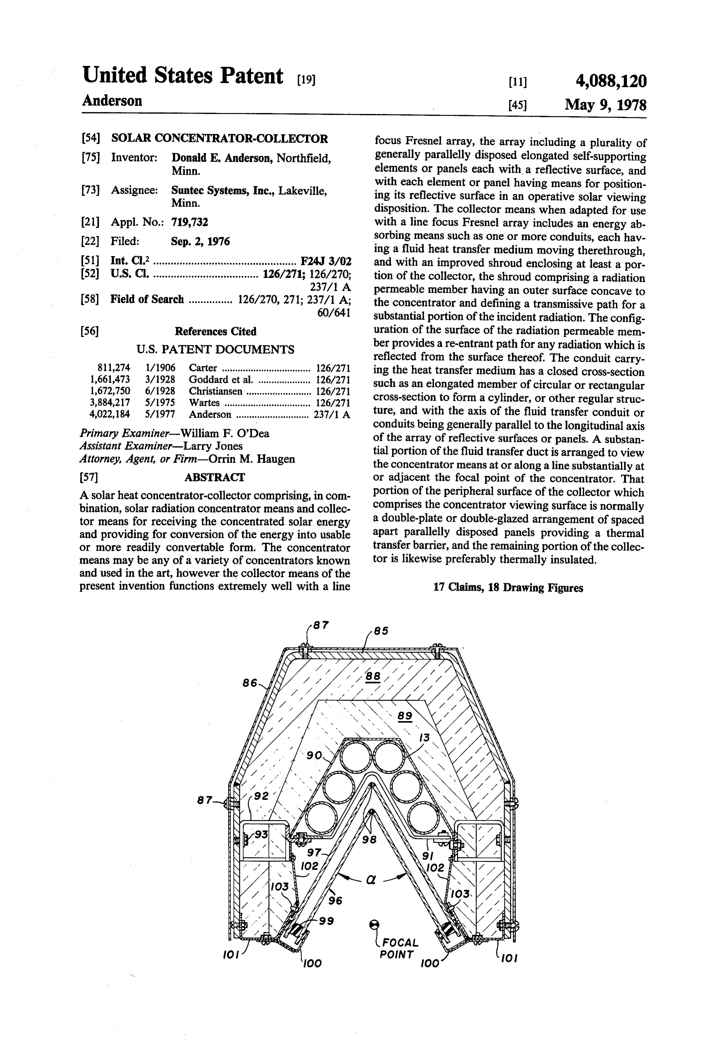
United States Patent (19) 11) 4,088,120 Anderson 45) May 9, 1978 (54) soLAR CONCENTRATOR-COLLECTOR focus Fresnel array, the array including a plurality of 75 Inventor: Donald E. Anderson, Northfield, generally parallelly disposed elongated self-supporting Minn. elements or panels each with a reflective surface, and 73) Assignee: Suntec Systems, Inc., Lakeville, with each element or panel having means for position Minn. ing its reflective surface in an operative solar viewing disposition. The collector means when adapted for use 21 Appl. No.: 719,732 with a line focus Fresnel array includes an energy ab (22 Filed: Sep. 2, 1976 sorbing means such as one or more conduits, each hav ing a fluid heat transfer medium moving therethrough, 51) Int. Cl’................................................. F24J 3/02 and with an improved shroud enclosing at least a por 52 U.S. C. .................................... 126/271; 126/270; tion of the collector, the shroud comprising a radiation 237/1 A permeable member having an outer surface concave to 58) Field of Search ............... 126/270, 271; 237/1 A; the concentrator and defining a transmissive path for a 60/641 substantial portion of the incident radiation. The config (56) References Cited uration of the surface of the radiation permeable mem
reflected from the surface thereof. The conduit carry 811,274 1/1906 Carter .................................. 126/271 ing the heat transfer medium has a closed cross-section 1,661,473 3/1928 Goddard et al. ... 126/271 such as an elongated member of circular or rectangular 1,672,750 6/1928 Christiansen ..... ... 126/271 cross-section to form a cylinder, or other regular struc 3,884,217 5/1975 Wartes ......... ... 126/27 4,022,184 5/1977 Anderson ............................ 237/1 A ture, and with the axis of the fluid transfer conduit or conduits being generally parallel to the longitudinal axis
Primary Examiner-William F. O'Dea of the array of reflective surfaces or panels. A substan Assistant Examiner-Larry Jones tial portion of the fluid transfer duct is arranged to view Attorney, Agent, or Firm-Orrin M. Haugen the concentrator means at or along a line substantially at 57 ABSTRACT or adjacent the focal point of the concentrator. That A solar heat concentrator-collector comprising, in com portion of the peripheral surface of the collector which bination, solar radiation concentrator means and collec comprises the concentrator viewing surface is normally tor means for receiving the concentrated solar energy a double-plate or double-glazed arrangement of spaced and providing for conversion of the energy into usable apart parallelly disposed panels providing a thermal or more readily convertable form. The concentrator transfer barrier, and the remaining portion of the collec means may be any of a variety of concentrators known tor is likewise preferably thermally insulated. and used in the art, however the collector means of the present invention functions extremely well with a line 17 Claims, 18 Drawing Figures
Page 2
Drawing sheet — no readable text.
Page 3
Drawing sheet — no readable text.
Page 4
Drawing sheet — no readable text.
Page 5
Drawing sheet — no readable text.
Page 6
Drawing sheet — no readable text.
Page 7
Drawing sheet — no readable text.
Page 8
Drawing sheet — no readable text.
Page 9
Drawing sheet — no readable text.
Page 10
S 1.5 O-O SOUTH FACING
L A-tes-A O VERTICAL COLLECTOR
1 \ ya A A 6o FROM HorizoNTAL
S O.5 YOU O 3O FROM HORIZONTAL
50° N. LATITUDE FIG. 5
IOO -ACRYLIC - SILVER, IN CONEL
FEP TEFLON,
/ --ALUMINIZED OPTICAL FLAT
A LUMNIZED 2 MIL MYLAR
4O "ALZAK" POLISHED A LUMINUM
BEAM SPREAD, nr.
FIG 16
Page 11
SOLAR CONCENTRATOR-COLLECTOR
supports must be provided. A further problem has ex isted with most flat plate solar heating elements, due to
CROSS-REFERENCE TO RELATED the low velocities normally utilized in the system. With APPLICATION low velocities, fluid corrosion and plugging of transmis sion lines may be more likely to occur than in systems
The present invention is an improved collector which employing high velocity fluid transfer. may be used in combination with the concentrator dis In the present solar heat concentrator-collector sys closed and claimed in my co-pending application Ser. tem, the design illustrated is one preferably employing a No. 556,650, filed Mar. 10, 1975, entitled "Lateral Lens concentrator with generally horizontally disposed cyl Arrangement for Solar Energy Conversion Devices' 10 inders, parabolas or elongated flat plates forming an now U.S. Pat. No. 4,022,184, May 10, 1977 and assigned array of reflector panels. The collector preferably com to the same assignee as the present case. prises an elongated structure having its axis generally BACKGROUND OF THE INVENTION parallel to the axis of the cylindrical elements forming The present invention relates generally to an im 15 trator the array, the collector being provided with a concen proved solar energy concentrator-collector, and more lecting viewing surface which provides a means for col particularly to a energy collector for use with a solar energy that portion of the incident concentrated solar which is initially reflected from the surface of heat concentrator of the line focus type. The entire the viewing window. While a horizontally disposed system includes, in combination, an array of reflective panels forming a solar radiation concentrator, and a 20 concentrator-collector arrangement is normally pre collector or absorber means cooperating with the array ferred, vertically disposed systems may be employed if for receiving the concentrated solar energy. The collec desired.
tor provides an efficient system for receiving concen It has been predicted that the total electrical power trated solar energy, with the collector having a concen demand for the United States of America in the year trator-viewing window or surface which transmits a 25 1980 will be approximately 9 x 10² Kilowatt-hours. substantially increased portion of incident radiation, by This power demand is substantially equivalent to that providing a re-entrant path for any incident radiation amount of incident solar radiation falling upon an area from the concentrator which may otherwise be re of only 1,531 square miles of land area located at ap flected from the surface of the window. With the con proximately 33° North Latitude in a given year. Such a tinuing utilization and ultimate partial depletion of 30 latitude is substantially coincident with that passing available fossil fuels, use of alternate sources of energy through the State of Arizona. Assuming an efficiency of has become desirable, provided feasible means and tech conversion of solar energy to electrical energy of only niques can be found for their utilization. In this connec 15 percent, the area required to obtain the projected tion, solar energy may be employed as a high-grade electrical power demand for the United States of Amer non-polluting source for the generation of usable en 35 ica in the year 1980 is approximately 10,000 square ergy with this source of energy being freely available. miles, with the area reasonably being expected to pro Conversion of solar energy into usable energy may vide at least a substantial portion of the projected elec typically be achieved by thermodynamic arrangements, trical power demand for the United States of America such as, for example, by the generation of steam or for the calendar year 1980.
other heated fluid for ultimate utilization at a power 40 Solar energy is, of course, available for immediate conversion site. One approach which is commonly conversion without further depletion or utilization of taken for conversion of solar energy is the utilization of fossil fuels. The system of the present invention renders flat absorbers to heat a fluid transfer medium such as it possible to fabricate relatively modest solar energy water, the heated water then being transferred to either conversion plants suitable for use in heating and cooling a thermally insulated reservoir or a zone wherein heat 45 of residential dwellings, as well as commerical establish may be extracted. Such absorbers are normally referred ments with modest to moderate power requirements. to as "flat plate collectors'. Since collector surface This system efficiently and economically converts solar areas must be substantial, the cost of such collectors energy to other usable forms of energy at an amortized along with the thermal efficiency at low ambient tem cost no greater than that cost required for fossil fuel peratures renders certain designs disadvantageous. 50 conversion.
These disadvantages are overcome with the structure Except for the State of Alaska, at those latitudes in and design of the present invention. which the balance of the United States of America is In conventional or known solar energy systems, such situated, sunlight is never available on a 24-hour per day as flat plate collectors or the like, a number of common basis, and at the same time, each day of the solar year problems have existed and the existence of these prob 55 provides a certain reasonable amount of potential sun lems has retarded the growth and acceptance of solar light. The sun is, nevertheless, available for exposure to heating systems. Normally, the primary problem is the the surface of the ground for a maximum of 50 percent initial on-site installation cost, with this cost normally of the total time of a given year within any given loca being large due to the excessive size of conventional or tion. Depending upon climatic conditions, there will be effective systems. Furthermore, complex manifolding 60 a reduction from the 50 percent maximum occasioned of the individual collectors in the system has presented by cloud cover, as well as a reduction due to the pres problems due to leakage. The weight of the installation ence of natural or artificial obstacles. However, with has also presented problems, particularly the weight of the time available for exposure to the sun, it is, never a fully loaded flat plate fluid collection system. When a theless, economically feasible to employ solar energy as roof mounted flat plate fluid system is specified, particu 65 the primary source of energy, with this primary source larly in an existing building structure, the load bearing being supplemented by available fossil fuels. It will be capability of the structure is frequently insufficient to appreciated that the utilization of fossil fuels may be support the fluid-loaded systems and added structural required only during the nighttime hours, or upon the
Page 12
occurrence of periods of heavy and extended cloud reflective array. Means are provided for the purpose of COWe, compensating for diurnal changes in solar elevation,
SUMMARY OF THE INVENTION
thereby adjustably positioning the angular elevational disposition of each of the reflective surfaces into a de
The concentrator-collector of the present invention sired solar viewing disposition relative to the stationary preferably employs an array of solar reflectors or pan collector. The individual reflective elements are ganged els, grouped together so as to form a solar radiation together so as to tiltably compensate for solar elevation concentrator means in the form of a line focus Fresnel changes, with linkage means being provided to effec array, with each of the reflective elements or panels tively gang the surfaces together. Inasmuch as the con being focused upon the window of a solar collector O centrator array and collector each contemplate a line means. The collector is preferably in the form of one or focus, azimuth compensation is not normally required. more elongated elements of generally rectangular cross Also, means are normally provided for rotatably posi section, or of elongated cylindrical elements, with a tioning the individual reflective elements forming the protective shroud being provided. At least a portion of array in inverted inoperative or idle disposition so as to the shroud is an energy transmissive window to trans 15 provide a means of protecting the surface from contin mit concentrated solar energy from the concentrator to ued exposure to the elements, such as adverse condi the absorption element or elements, with the window tions due to hail, blowing dust, and the like. having an outer surface which is generally concave to The axis of the collector means preferably extends the concentrator surface to provide for re-entry of re generally parallel to the elongated axis of the reflective flected radiation and thus a more efficient collection of 20 surfaces. The cylindrical fluid transfer duct of the col the concentrated solar energy. In other words, the con lector has a closed peripheral surface, with the outer cave configuration, when arranged in conformance periphery of the collector forming a shroud for the duct with the aspects of the present invention, provides an and having an energy transmitting zone or window efficient re-entrant path for any portion of the incident arranged in viewing relationship to the reflective con radiation which may be reflected from the window 25 centrator surfaces, with this window portion of the surface. With the system of the present invention, as in shroud being disposed at, along or adjacent the focal certain others, it is possible to achieve solar power de point of the line focus Fresnel array. That portion of the pendency for a given installation in substantial excess of periphery of the fluid transfer duct which is not in view the available sun time by means of utilization of energy ing relationship to the reflective elements, or is other storage, such as, for example, the use of heat pumps, 30 wise remote from the focal point, is normally covered thermal storage vessels, thermal energy storage vessels with a thermal barrier for substantially reducing ther utilizing latent heat of evaporation and condensation of mal energy losses from the fluid transfer duct, with the a captive fluid, reversible hydraulic pumping, reversible shroud forming the outer surface of the collector, and electrolysis or electrolytic cells, or electrolysis with normally defining an annular zone restricting transfer of storage of evolved oxygen and hydrogen. In the elec 35 thermal energy, such as an annular zone filled with a trolysis system, the evolved gases subsequently are thermally insulative substance. Preferably, the collector combined for burning, thus replacing the fossil fuels means is disposed at a location between the sun and the which may otherwise be required. At the present time, reflective surfaces, and mounted at an elevation which local weather forecasting techniques are sufficiently is vertically above the plane of the reflective elements. sophisticated so as to provide a reasonably accurate In order to concentrate the incident solar radiation, the prediction for at least a 24-hour period, hence it is rea elongated reflective elements which form the reflective sonably possible to anticipate demand requirements and surfaces are preferably formed as arcuate segments ultimate availability of solar energy to meet these fore defining cylinders or parabolas, although it will be ap cast demand requirements. preciated that flat reflective surfaces may be employed Briefly, in accordance with the present invention, a 45 in certain installations as well. The focal length of each solar heat concentrator-collector is provided which of the parabolas will therefore be substantially equal to includes an array of reflective panels comprising solar the distance from the reflective surface to the surface of reflective element or concentrator which functions in the absorber means. In order to accommodate the diur combination with collector means for receiving the nal arcuate elevational movements of the sun, the indi concentrated energy and providing for conversion of 50 vidual cylindrical reflective parabolas will be arcuately the energy into a form which will render it usable. The rotated at a rate compensating for these movements or collector is provided with a concentrator viewing win changes in elevation during the daytime hours. Prefera dow which has a configuration such that any incident bly, the individual structures carrying the reflective radiation from the collector which is reflected from the surfaces are ganged together so as to move the surface surface of the window is reflected along a path which 55 as a unit. In other words, in order to compensate for accommodates or permits re-entry of the reflected en differences in the angular reflection required to focus ergy to a second or remote point along the window the reflective surfaces onto the absorber means, the surface. Also, for thermal insulation considerations, the mounting angle of the individual panels will be adjusted window is preferably in the form of a double window to achieve the approximation of a lateral Fresnel lens. arrangement with a pair of parallelly disposed panes or 60 Accordingly, the entire array of cylindrical parabolas panels being arranged in spaced apart relationship, both may be rotated in time with the diurnal movements of “panes' of the concentrator viewing window being the sun in order to maintain the focal point for the inci provided with or forming a concave surface which dent solar radiation upon the surface of the absorber accommodates re-entry of any reflected radiation. SeaS.
The concentrator portion preferably comprises a 65 Also, in order to protect the reflective surfaces from plurality of generally parallelly disposed elongated ele adverse weather conditions such as hail storms, dust ments or panels, each having a reflective surface storms, and the like, means are provided for rotating the thereon so as to form, for example, a line focus Fresnel individual reflective surfaces to an inoperative or idle
Page 13
disposition wherein the reflective surfaces are pointed of panels and a collector means for receiving the con downwardly toward the ground or toward any other centrated solar energy, the collector means preferably supporting surface. In certain instances, it may be desir including an elongated fluid transfer duct with an axis able to provide for adjustably tilting the elevation angle extending generally parallel to the elongated axis of the of the lateral end support columns for the arrays so as to 5 reflective array, and with the peripheral surface of the maximize the effectiveness of the reflective surfaces, collector defining a shroud having a window portion while minimizing shadowing effects. therein disposed generally concave to the collector Adjustable control of the angular disposition of the elements, and with the absorber means of the collector individual reflective elements may be accomplished including a thermal energy absorptive zone and a ther with a single drive motor operating a gang of pre 10 mal insulative Zone, with the absorptive zone being arranged reflective elements or panels. Similar tech enclosed by said shroud, and being disposed in viewing niques may be utilized in order to control the angular relationship to the reflective surfaces of the reflective disposition of the lateral support elements so as to array and generally within or closely adjacent the focal achieve control of the "shadowing effect" of individual line thereof.
reflective elements, one upon another, however due to 15 It is yet a further object of the present invention to the slow rate of change of solar elevation between the provide an improved solar concentrator-collector seasons of the year, this angular adjustment feature need means which employs a solar radiation concentrator not be automatically accomplished.
means and a collector means for receiving concentrated
The individual structures forming the reflective sur Solar energy, the solar radiation concentrator means faces are normally designed to be held in end support 20 comprising columns. Therefore, it is preferable that the individual elements a plurality of generally parallelly disposed elements forming the reflective assemblies be free forming a line focus Fresnel array, each ele standing, non-deforming, and accordingly optically ment having a reflective surface with the focal line of stable for greater utility in combination with the ab each of the reflective surfaces being generally coinci sorber means of the present invention. Inasmuch as the 25 dent means with the surface of the absorber means, and with being provided to form a shroud about said ab individual elements are ganged together, and inasmuch sorber means, said shroud including a window which as the elements may be rotated from only one of the two provides spaced end supports, the individual cylinders or parabo for the surface of the absorber means to view las forming the panels or elements will be functioning as the concentrator, the window of the shroud being pro vided with means for effectively capturing substantially torque-tubes and therefore they should be sufficiently 30 all rigid so as to withstand the forces to which they are incident concentrated radiation. subjected. The mechanical requirements for the ab It is yet a further object of the present invention to sorber are, of course, consistent with those of the reflec provide an improved solar heat concentrator which tors. The collector must be sufficiently rigid so as to be comprises a solar radiation concentrator-collector non-deforming between supports, and must be capable 35 means for receiving concentrated solar energy, wherein of compliance while withstanding the thermal varia the collector means includes an absorber means and a tions consistent with the design temperatures to which shroud surrounding said absorber means, said shroud it is being exposed. including a window element which transmits concen Because of the design characteristics and features of trated Solar energy from the concentrator to the ab the system, it is possible to retro-fit the system to exist 40 sorber means, and further provides for a re-entrant path ing structures as well as to apply the system as the pri for any incident concentrated solar energy which may mary thermal system in new construction. The capabil be reflected from the window surfaces. ity of protecting the individual reflective elements dur Other and further objects of the present invention ing extreme weather conditions also provides a safe will become apparent to those skilled in the art upon a guard against burn-out of the collector under no-load 45 study of the following specification, appended claims, conditions. In other words, under a situation wherein and accompanying drawings.
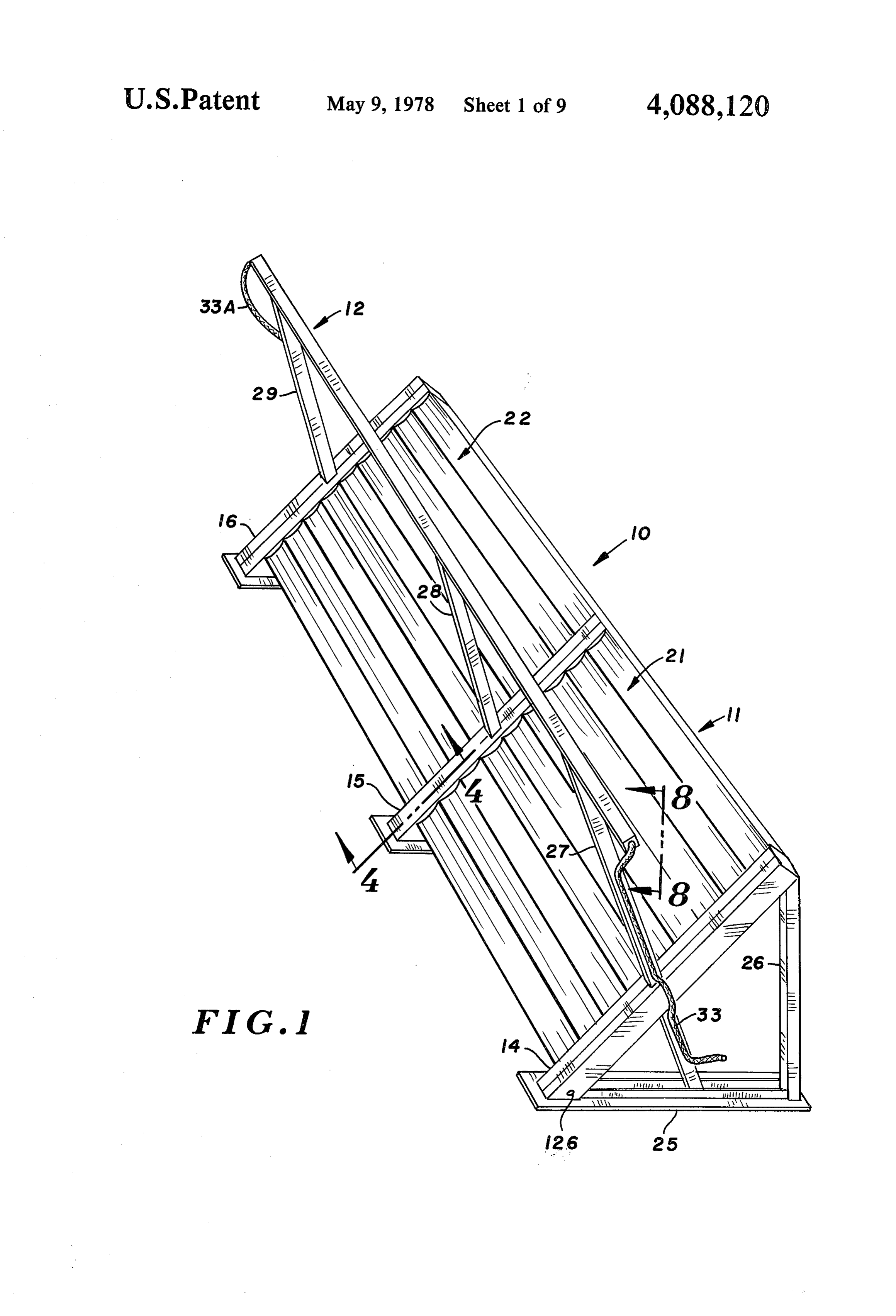
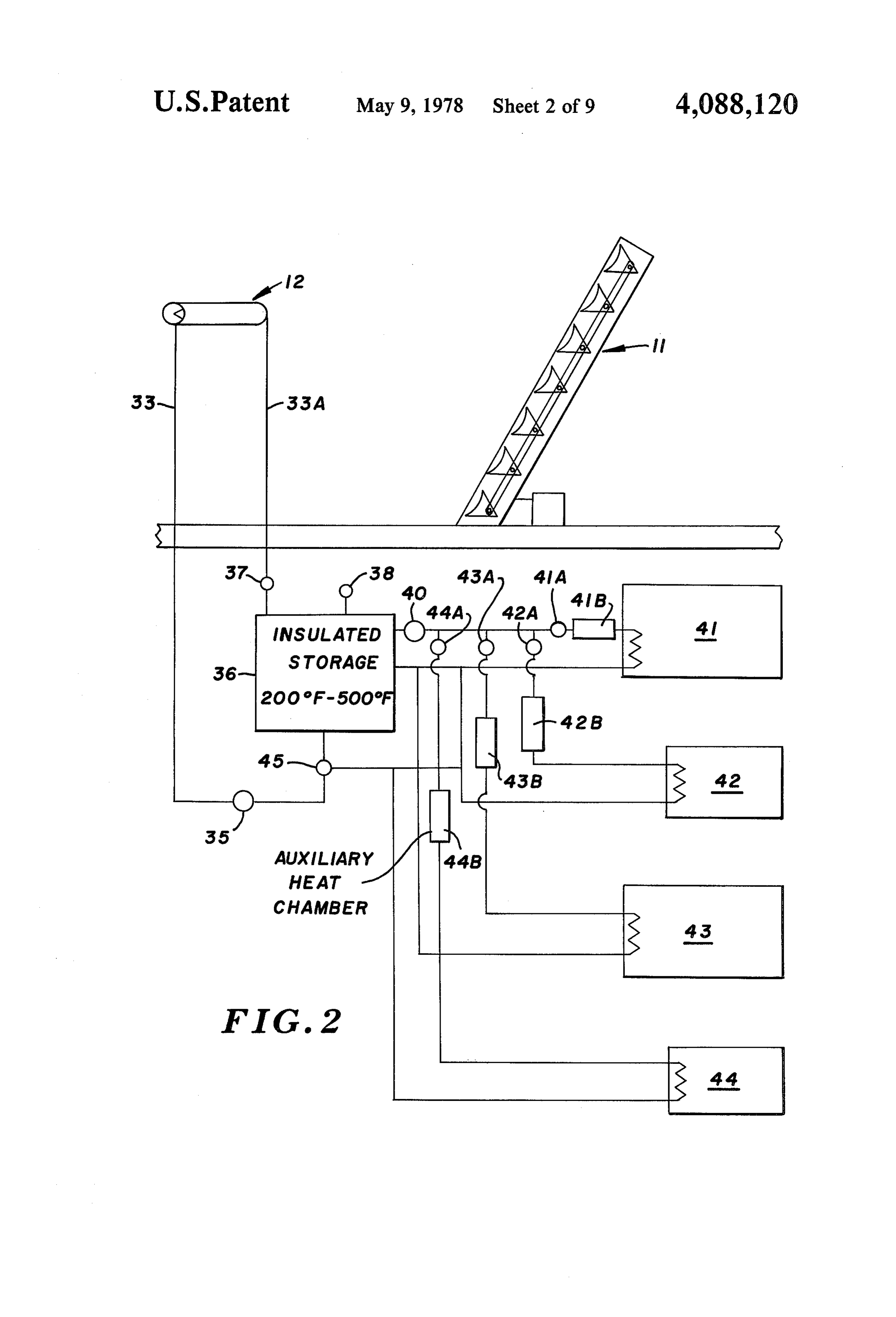
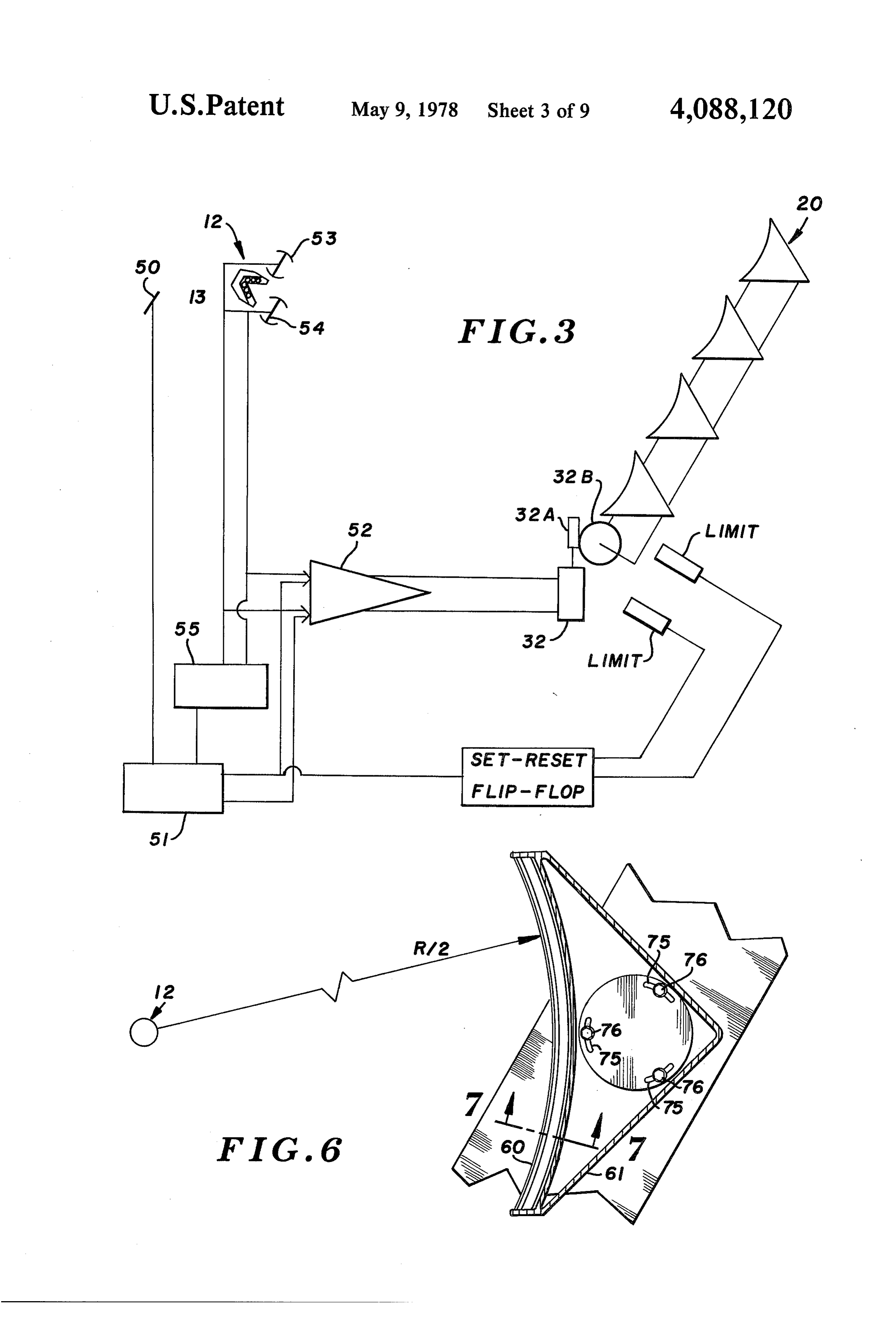
there is no call for additional energy, the individual BRIEF DESCRIPTION OF THE DRAWINGS reflector elements forming the line focus Fresnel array are de-focused, such as by rotating the panels to turn the FIG. 1 is a perspective view of a typical installation reflective surface toward the ground. 50 utilizing the improved collector of the present inven By way of location relative to the demand area, it will tion, with the concentrator portion being in the form of be appreciated that the concentrator-collector may be a line focus Fresnel array of reflective elements; used in any location with good sun exposure. Examples FIG. 2 is a schematic diagram of the system of FIG. of such locations include parking lots, fence lines, roofs 1 and illustrating one typical application to be employed of commercial and residental structures, and south-fac 55 for the structure of FIG. 1;
ing walls. FIG. 3 is a schematic diagram of a drive and tracking Therefore, it is a primary object of the present inven system which may be employed in combination with tion to provide an improved solar heat concentrator the system of the present invention;
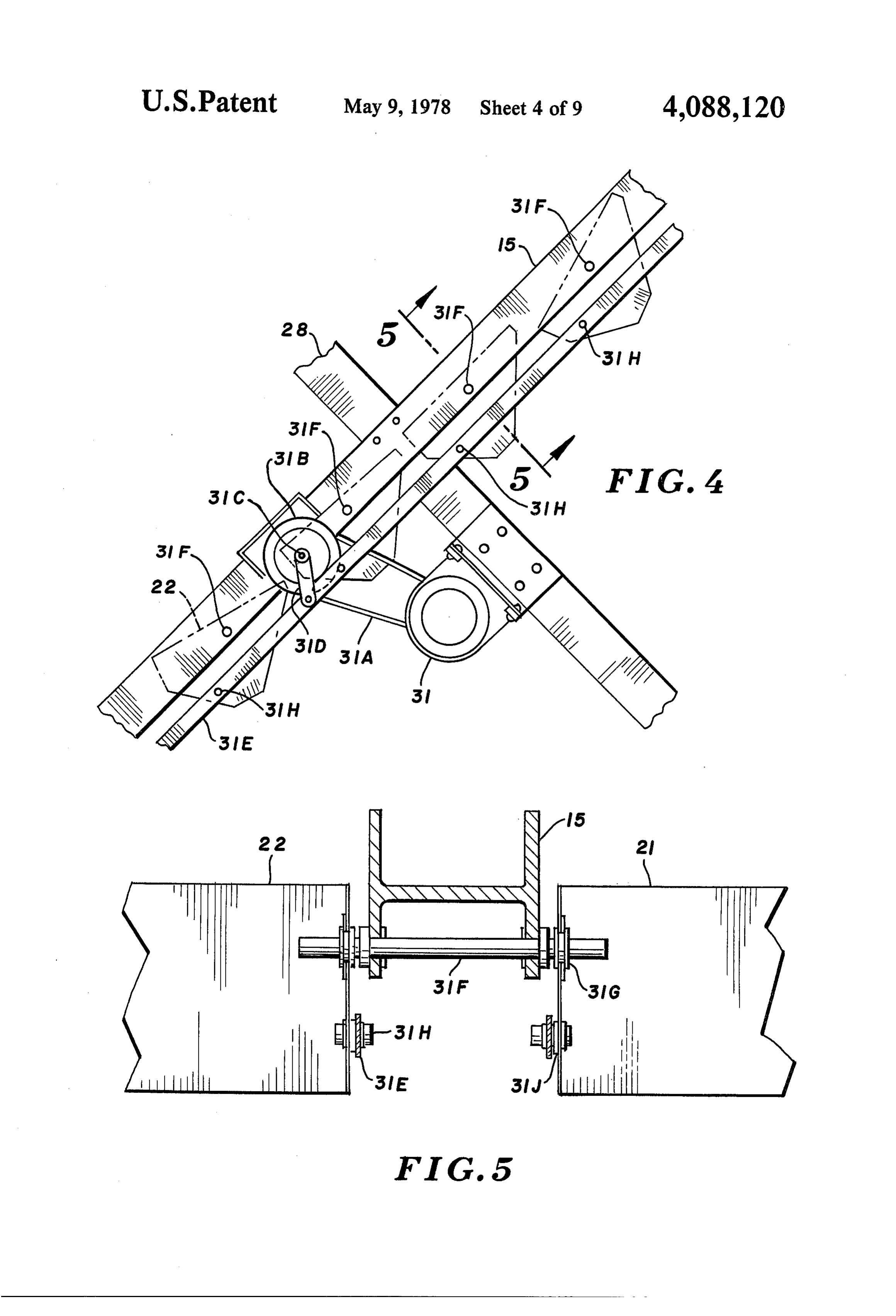
which comprises in combination, a solar radiation con FIG. 4 is a side elevational view on a slightly en centrator-collector means, the collector being arranged larged scale taken along the line and in the direction of for receiving the solar energy from the concentrator in the arrows 4-4 of FIG. 1 and illustrating the details of efficient fashion, providing for at least one re-entrant a typical drive system for the line focus Fresnel array; path for solar energy reaching the collector from the FIG. 4A is a view similar to FIG.4, but illustrating a concentrator. slightly modified form of drive system for the line focus It is a further object of the present invention to pro 65 Fresnel array;
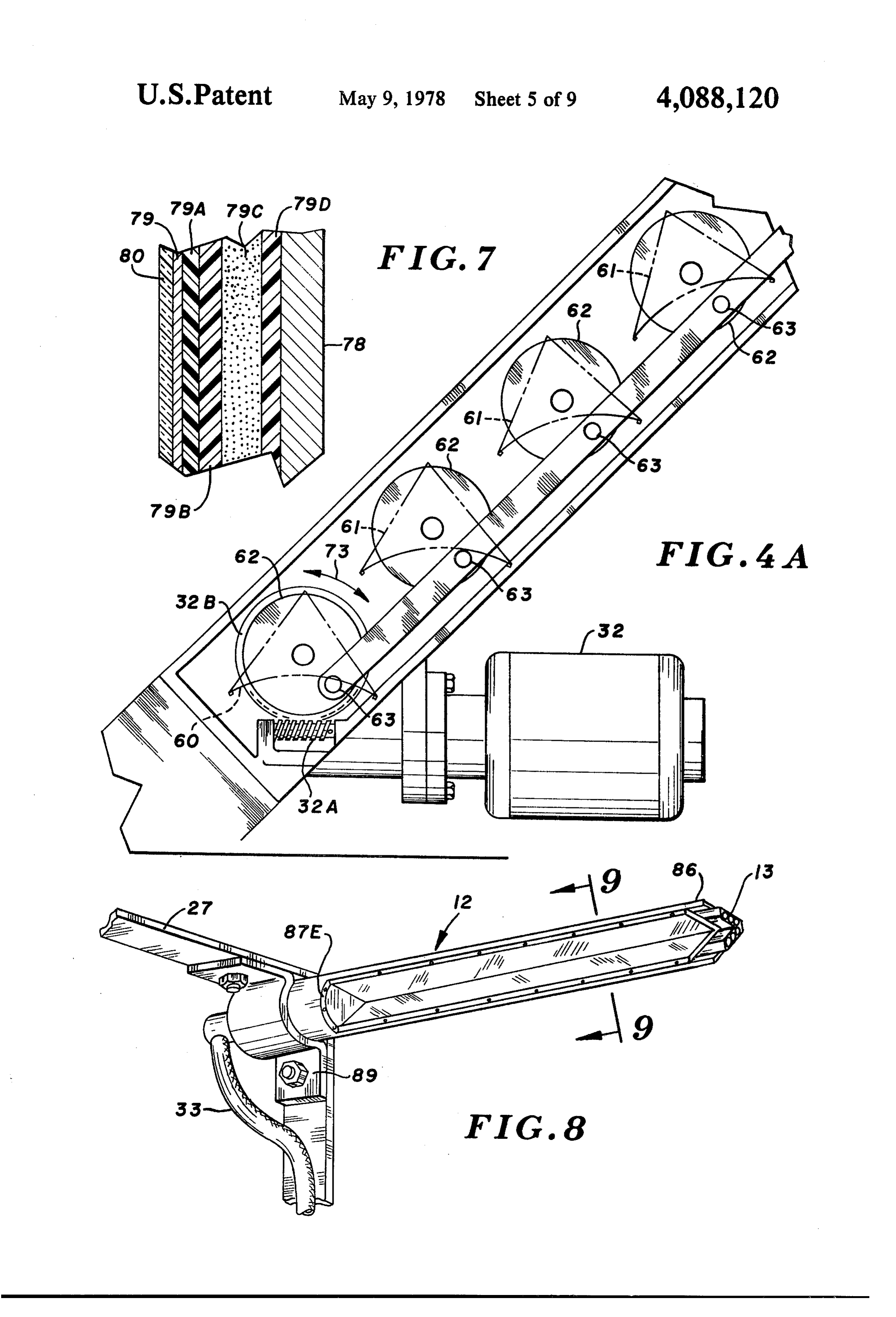
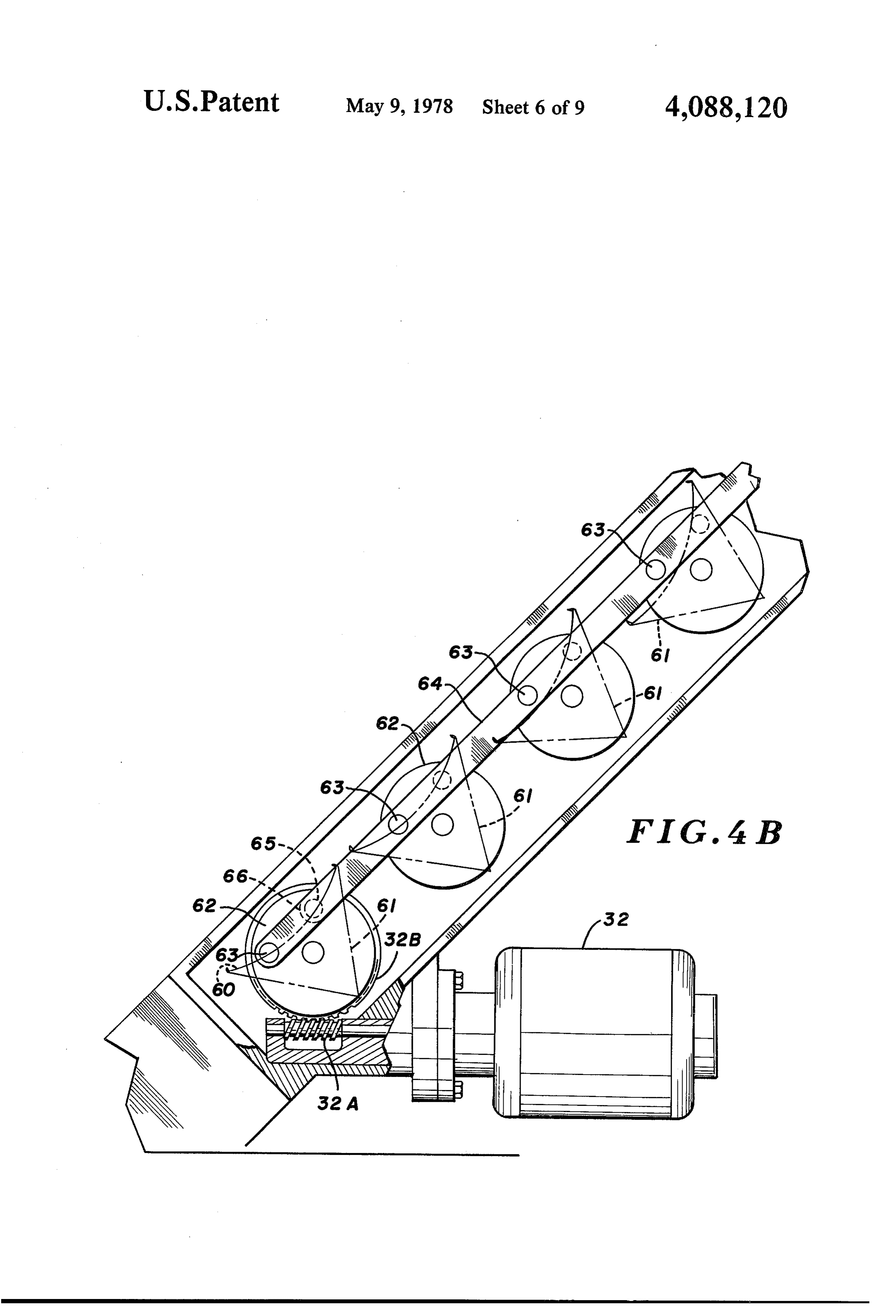
vide an improved solar heat concentrator-collector FIG. 4B is a view similar to FIG. 4A, but illustrating which comprises in combination, a solar radiation con the individual members forming the line focus Fresnel centrator means in the form of a line focus Fresnel array array in solar viewing disposition;
Page 14
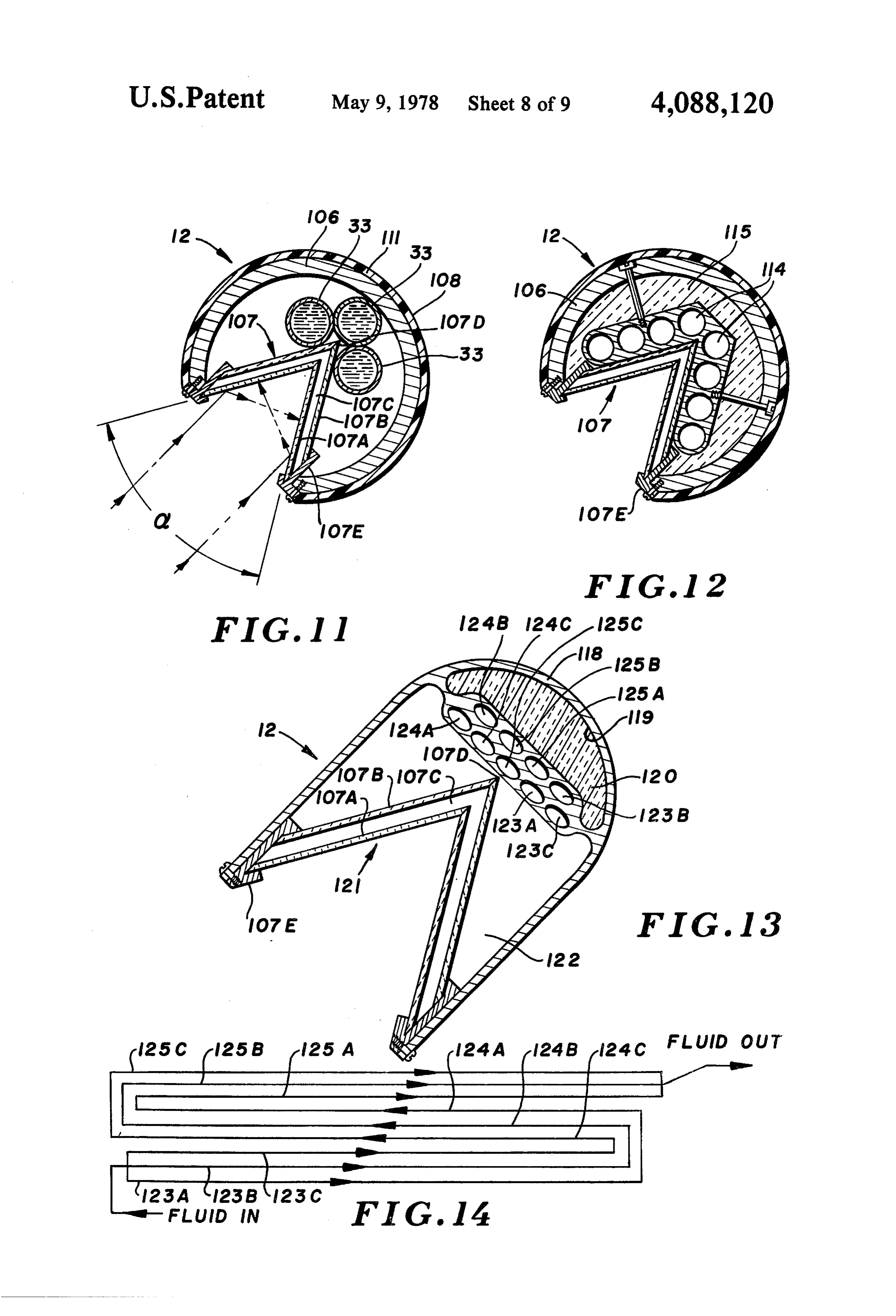
FIG. 5 is a detail sectional view of the drive means being identified at 21 and 22. Each of the individual slats illustrated in FIG. 4, and taken along the line and in the or cylindrical parabolas incorporated in the system is direction of the arrows 5-5 of FIG. 4; identical, one to the other, and hence the description of FIG. 6 is a detail side elevational view of a typical one such element will suffice for a description of all. reflective panel in the array, and being in the form of a 5 Support means are provided for the concentrator cylindrical parabola, and illustrating the disposition of means such as a base pad 25 having support posts along the panel relative to the absorber means, this figure each of the columns 14, 15, and 16 as at 26. A bracket being shown in fragmentary form; means is provided for supporting the collector 12 along FIG. 7 is a detail sectional view of a slightly enlarged each column as well, such as is illustrated at 27, 28, and scale, and taken along the line and in the direction of the O 29. Base pads 25 also provide support for the individual arrows 7-7 of FIG. 6; columns 14-16 inclusive, such as shown. As will be FIG. 8 is a fragmentary view of an end portion of the made more apparent hereinafter, a drive motor is pro collector means illustrated in FIG. 1, with this view vided for the arrays 20 and 21 such as is illustrated at 31 being taken along the line and in the direction of the in FIG. 4, with an alternate version being illustrated at arrows 8-8 of FIG. 1; 15 32 in FIG. 5, in each instance, the arrangement being FIG. 9 is an enlarged vertical sectional view of the such that one motor drives one or more arrays. Transfer collector means illustrated in FIG. 8, and is taken along fluid is provided for the absorber element or portion 13 the line and in the direction of the arrows 9-9 of FIG. of the collector through a liquid feed line 33, with an 8; outlet or discharge line (33A) being provided at one of FIG. 10 is a sectional view of the absorber column 20 the ends, such as at the opposed end of absorber element shown in FIG. 9, and illustrating schematically the 13 of the collector 12.
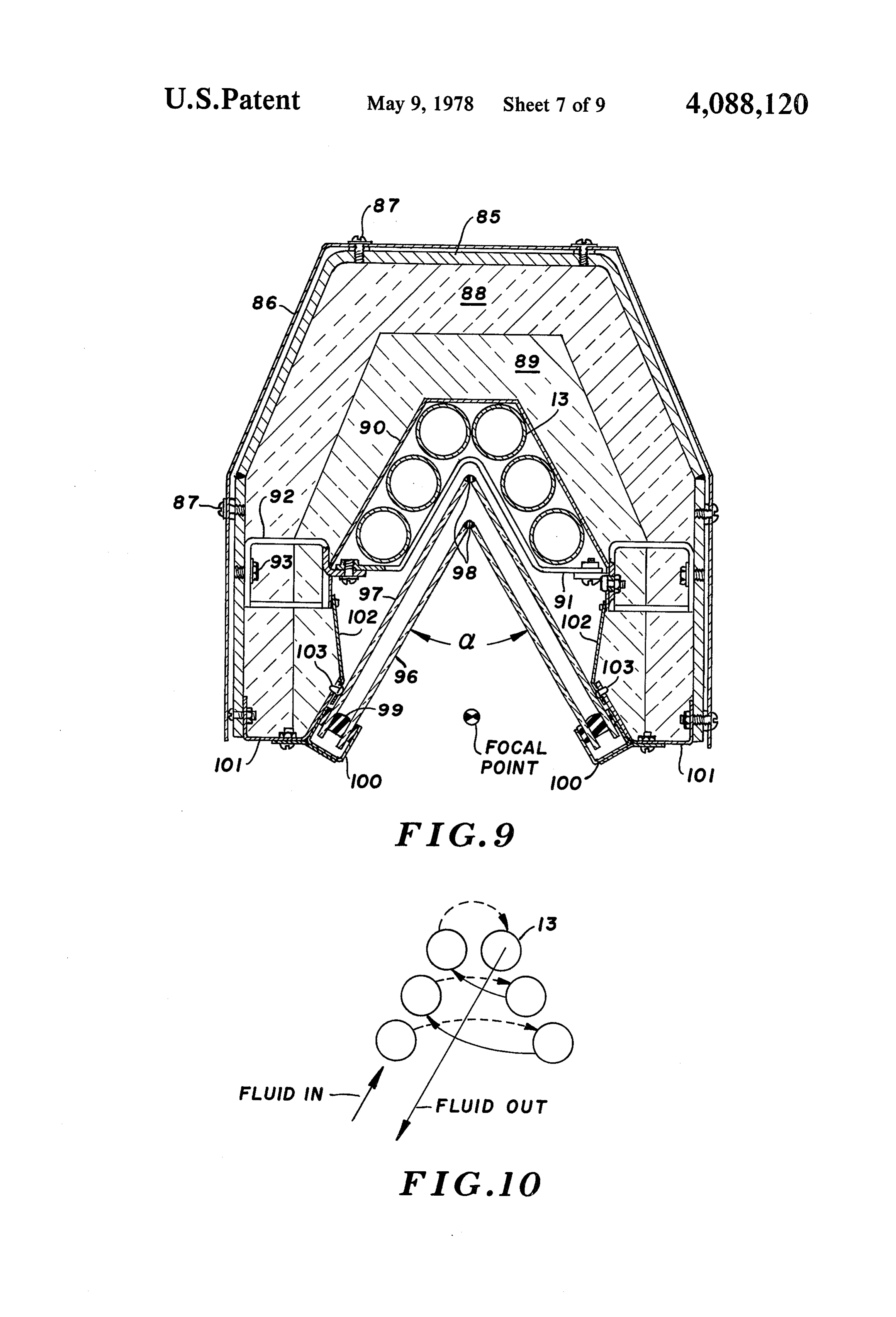
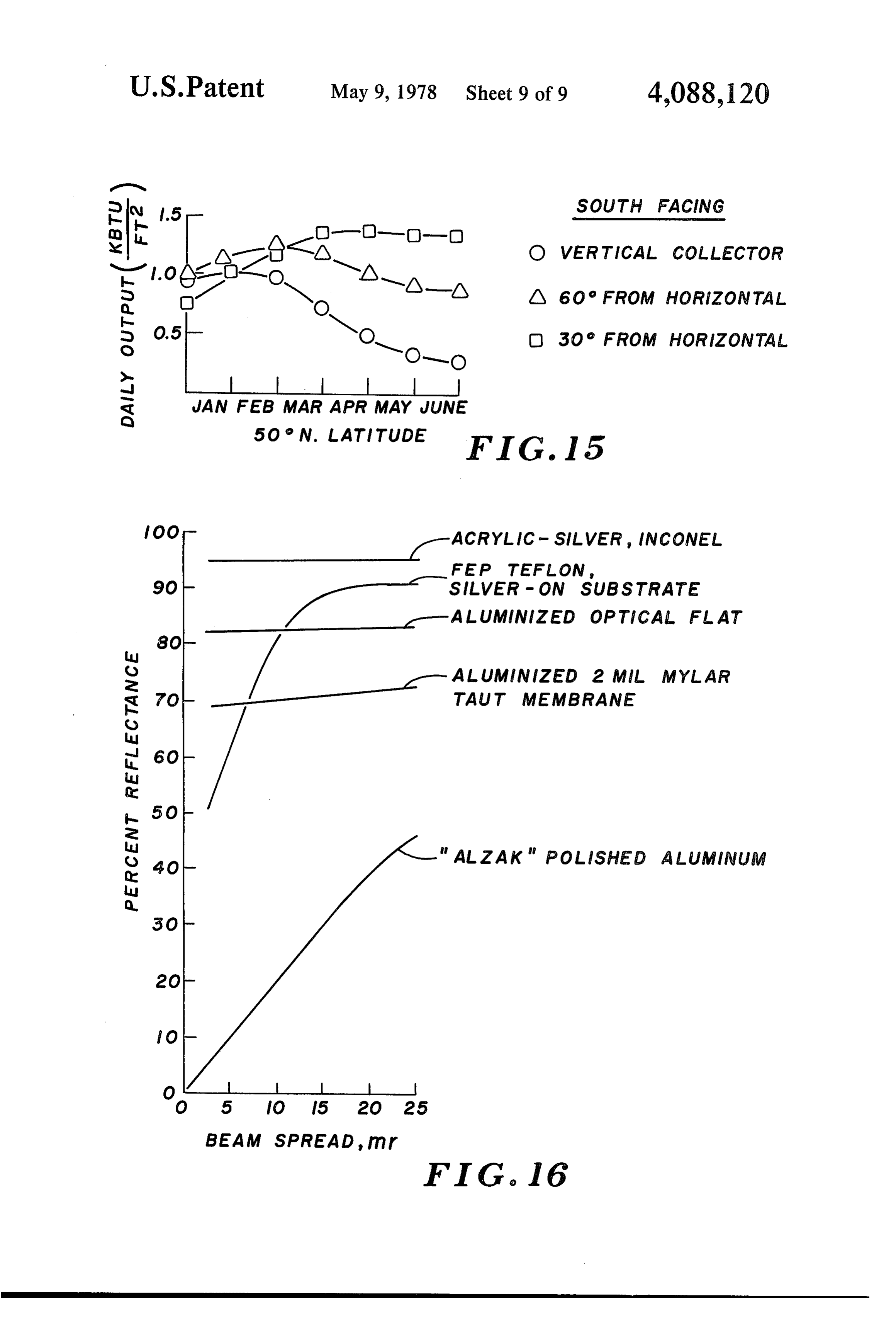
typical flow arrangement through the system; As has been indicated, the individual reflectors are FIG. 11 is a view similar to FIG. 9, and illustrating a ganged together so as to achieve a line focus on the modified form of collector means utilizing an absorber collector, and preferably on or along the element or comprising a plurality of axially parallelly disposed 25 component forming the absorber 13. With attention fluid transfer ducts; now being directed to FIG. 2 of the drawings, an exam FIG. 12 is a view similar to FIGS. 9 and 11, and ple of a system schematic is illustrated wherein a line illustrating still another modified form of absorber focus Fresnel array of reflectors in the system 11 is means which may be employed in the collector means focused upon the collector 12, with an inlet line to the of the present invention; 30 absorber 13 being illustrated at 33 and an outlet or dis FIG. 13 is a view similar to FIGS. 9,11 and 12, and charge line being illustrated at 33A. The heated fluid illustrating a further modified form of absorber means passing through the absorber 13 of collector 12 is fo which may be employed in the collector means of the cused by means of pump 35, with insulated storage present invention; vessel 36 being employed to retain the heated fluid for FIG. 14 is a typical flow diagram which may be em 35 distribution through other zones, as required. Storage ployed in the arrangement illustrated in FIG. 13; vessel 36 is adapted to retain fluid at an elevated temper FIG. 15 is a graph illustrating a family of curves ature, such as from 200 F. to about 500 F. Tempera plotting daily output in BTU's vs. months of the calen ture gauges 37 and 38 monitor the condition of the fluid dar year at 40 North Latitude, with each member of entering the vessel 36 as well as the material within the family of curves illustrating a different degree of 40 vessel 36. Pump 40 is used to carry fluid from vessel 36 inclination from the horizontal for the lateral supports to any of the working stations or zones such as the heat of the line focus Fresnel array of reflectors, of the type exchanger for building heat as at 41, a hot water tank as illustrated in FIG. 1; and at 42, a heat exchanger for absorbing air conditioning as FIG. 16 is a plot of the measure of specular reflectiv at 43, as well as a zone for process heating as at 44. ity of various laminate materials useful in the fabrication 45 Alternatively, a mechanically coupled compressor may of the reflective panels employed in the present inven be utilized to provide air conditioning and potential tion, plotting percent reflectance vs. milli-radians of heat pumping with mechanical energy being delivered beam spread in the relevant range of requirements for by a Rankine Cycle Prime Mover powered by the the line focus Fresnel collector array. stored solar heat. In the illustrated system, individual 50 valves such as 41A, 42A, 43A and 44A control the flow
DESCRIPTION OF THE PREFERRED of fluid from pump 40 to each of the individual zones, as EMBODIMENT illustrated, with three-way valves 45 being employed to In accordance with the preferred embodiment of the direct the return flow either to storage vessel 36 or to present invention, and with particular attention being pump 35. Thus, it will be seen that the system has appli directed to FIG. 1 of the drawings, the solar heat col 55 cation to a variety of processes, and is essentially with lector system generally designated 10 comprises, in out limitation in this regard. Also, as has been indicated, combination, a solar radiation concentrator means in it is possible to employ auxiliary heat as at 41B, 42B, the form of a line focus Fresnel array generally desig 43B and 44B for the individual lines from vessel 36 in nated 11, together with a collector means generally order to deliver fluid at a constant elevated tempera designated 12, the collector including an absorber 13 60 ture.
retained within a shroud or enclosure zone. (See FIG. Attention is now directed to FIG. 3 of the drawings 9). In the concentrator means, a plurality of lateral sup wherein a drive and tracking system for the solar heat port columns are provided for the array 11 as at 14, 15, concentrator-collector arrangement of the present in and 16 with the support columns being provided to vention is illustrated.
establish spaced supports for the free-standing non 65 (A) Totally Unobstructed Sunlight deforming reflective plate elements such as the elements Upon sufficient light striking sun sensor 50, the No. 1 included in the array 11. As is apparent from FIG. 1, level discriminator 51 which is, in turn, coupled at its two individual arrays are being employed, these arrays output to differential amplifier 52 drives the differential
Page 15
amplifier 52 and, in turn, drive motor 32. The individual 4 and correspondingly at 32 in FIG. 4A and each is reflective panels as have been described at 20 in FIG. 1 provided with its appropriate drive linkage means. In rotate from the "storage' or protective mode as illus the embodiment illustrated in FIG. 4, drive motor 31, trated in FIG. 4A to the active mode as is illustrated in which is equipped with a speed reducer, utilizes a drive FIG. 3. In order to protect the immediate environment, pulley (not shown) upon which drive belt 31A turns. the drive motor 31 (FIG. 4) may, through its timing belt Drive belt is further coupled to driven pulley 31B or other suitable drive belt 31A, rotate pulley 31B so as which, in turn, rotates shaft 31C upon which is secured to position or otherwise individual reflector elements 20 link 31D. Link 31D is further pivotally coupled to link in a counterclockwise direction until focus is achieved age member 31E which, in turn, is pivotally coupled, as on the collector 12. In the embodiment illustrated in O illustrated, to each of the individual reflective elements FIG. 4A, worm gear drive member 32A and ring gear forming the array. In the embodiment illustrated in 32B drive the individual reflector elements 20 in a coun FIG. 4A, motor 32 has an output shaft upon which is terclockwise direction until focus is achieved on the secured worm 32A which, in turn, is in mesh with ring collector 12. Therefore, as shown in FIG. 3, the focused gear 32B on the base member of the array, such as re beam from the arrays disposed as in FIGS. 4 and 4B will 15 flective surface 60. Each of the individual reflector strike optimizing sensors 53 and 54 at which time the panels is stretched tautly across triangular frame ar No. 2 level discriminator as shown at 55 overrides the rangement 61, as illustrated in both FIGS. 4A and 6, output of sunsensor 50 and causes a signal to differential with the triangular frame 61 being sufficiently durable amplifier 52 which, in turn, is utilized to drive motor 32 and rigid so as to provide a torque-tube for the rotation and position the sun's image directly on the collector 20 of the individual members of the linear focus array, with pipe 12. Preferably, the sun sensors 53 and 54 will be the torque-tube functioning in non-deforming fashion. It disposed in a zone such that direct incident reflected will be apparent that the elements forming the reflective light does not impinge directly on the surface of the panels 22 in FIG. 4 are likewise sufficiently durable and sensor. This is due to the high intensities involved. rigid so as to provide a torque-tube for the rotation of Therefore, these optimizing sensors 53 and 54 will nor 25 the individual members of the array. Deformation mally be disposed within a housing seeing a modest would, of course, present problems in the ultimate fo amount of reflected energy only. cusing of the individual members on the collector pipe (B) Intermittent Sun Failure surface.
A built-in time delay allows the No. 2 level discrimi In order to couple the individual reflectors together nator 55 to hold the panel members 20 in position. 30 in ganged relationship, crank pins are provided on the When the time delay, typically in the range of approxi circular end plates 62-62 of each of the panels shown mately five minutes is exceeded before reappearance of in FIGS. 4A and 4B, with the end plates carrying ec the sun, effective control will revert to the No. 1 level centric pins 63-63. Linkage arm 64 is, in turn, coupled discriminator 51 and the sensor input control reverts across each of the individual pins 63 so as to achieve from the optimizing sensors 53 and 54 to the sun sensor 35 ganged motion of each of the individual reflectors in the 50, array. The operational features of the arrangement illus (C) Total Sun Obstruction trated in FIG. 4 will, of course, be the same as that In the event of total sun failure or obstruction, the sun illustrated and described hereinabove with respect to sensor 50 is delivering no signal to No. 1 level discrimi FIGS. 4A and 4.B. In the event more than two individ nator 51, and this condition will be utilized to deliver a ual arrays are grouped together, the opposed end of the signal to differential amplifier 52 which will return the end column is likewise provided with a similar pin and reflectors 20 to the "storage' disposition or mode as is arm arrangement, with one such eccentric pin being illustrated in FIG. 6. As is indicated in FIG. 6, the re illustrated in phantom at 65. A second arm is then also flective surface is directed downwardly, toward the provided with the pins of the second arm being offset an surface of the ground, thereby enhancing the ability of 45 arcuate distance of 90' from those illustrated in solid the system to protect the face surfaces of the reflectors lines at 63 and 64 in FIG. 4. The reason for the offsetting from environmental damage during a storm or during is to avoid a condition of dead-centering in the arrange the occurrence of precipitation in the form of rain, ment, thus insuring a positive and full drive during snow, sleet or hail. periods of motion for all arrays. In the arrangement (D) High Limit Control 50 illustrated in FIG. 4, the central linkage arrangement is The system illustrated in FIG. 3 is adapted to utiliza used to adjustably position each of the reflective panels tion of a high limit control which may be a temperature in the arrays as at 21 and 22. Specifically, a pivot shaft gauge such as temperature gauge 37 illustrated in the is provided as at 31F which is appropriately journaled discharge line 33A of collector pipe 12 in FIG. 1, this in bearings as at 31G, with this shaft 31F having secured device acting as a condition sensing element to provide 55 thereto a link such as link 31D, as illustrated, for cou high limit control under modest or no-load conditions. pling to the individual reflectors 21 and 22 through This sensor may be utilized to provide a signal to differ pivot pin linkages such as at 31H. A covering plate is ential amplifier 52 which will override the sun sensor 50 preferably employed to eliminate dust and dirt from the and return the system to "storage' mode. This arrange confines of the arrangement. A dust and weather seal in ment will prevent continued operation and over-heating 60 the form of an "O" ring may be used, wherein sealing of the fluid contained in the system. engagement is made against the surface of cover mem GENERAL OPERATION ber and end plate of the reflector panel such as is illus trated at 31J of FIG. 5. It will be noted that the panel 21
Attention is now directed to FIGS. 4, 4A and 4B of and 22 illustrated in FIG. 5 may be any of the individual the drawings wherein details of one linkage means 65 panels in the array, with the exception of the panel which may be utilized to move the individual reflector carrying the drive mechanism, panels in the array is shown. The reversible drive mo It will be appreciated, of course, that in the event the tor, as previously discussed, is illustrated at 31 in FIG. individual reflective elements forming the concentrator
Page 16
may be moved to the "sheltered' mode in a downward structures, however any of the three configurations direct rotation, such as in a counter-clockwise direction may be useful. When curved reflective surfaces are in the view of FIG. 4. In this arrangement, it is, never employed, for sharper imaging the various radii of the theless, desirable to employ a structural arrangement mirrors will be selected so that the center mirror will which provides effective torque-tube operation during 5 possess the shorter focal length, with the focal length any rotational motion of the individual elements form increasing slightly from the center mirror to the edge ing the array. mirrors. In this fashion, the off-axis focal length of the Attention is now directed to FIG. 4A of the drawings various mirrors will be substantially the same, it being wherein the "storage' or "sheltered' mode is illus normally anticipated that the center mirror will reflect trated. In this disposition, the individual reflective ele 10 incident radiation substantially normal to the center of ments of the assembly have been actuated so as to return the reflective element.
to the "storage' disposition. As has been previously In preparing a typical reflector member, a mold sur indicated, the drive means is provided so as to de-focus face is provided having a convex surface for receiving the line arrangement by rotating the individual elements the sandwich of components making up the reflective in a clockwise direction from the disposition of FIG. 4 15 surface. The initial layer to be applied to the surface will to that disposition of the elements illustrated in FIG. be a film of stress-oriented polyethylene terephthalate 4A. Double-headed arrow 73 is shown for the purpose (Mylar) having a thickness of one-half mil, and being of illustrating the operational movement between the coated with aluminum, the aluminum having a thickness dispositions of the elements of the components of FIG. of at least about 1000 A. A layer of fiberglass is then 4A. 20
In order to provide for line focus of the array, on the applied ate to the stress-oriented polyethylene terephthal surface, and bonded thereto. Thereafter, a foam basis of a Fresnel array, and with attention being di backing having a thickness of approximately one inch is rected to FIG. 6, individual arcuate adjustment slots are applied to the fiberglass layer, in order to increase the shown at 75-75 together with mounting screws 76-76 modulus of the overall structure. The foam material is a which are employed to provide an initial adjustment of 25 structural foam such as polystyrene or polyurethane the surface of the reflector panel onto collector 12, as is having a density of approximately 2 pounds per cubic illustrated. The focal length of panel 60 is, in this in foot. The back surface of the foam member is thereafter stance, equal to the distance "R/2” as is illustrated in covered with a layer of fiberglass impregnated with a FIG. 6. In actual installation operations, therefore, the resin such as epoxy resin or the like. Each of the two installer will position each of the individual reflector 30 layers panels in the array so as to achieve a common focal line durableofresin fiberblass is preferably impregnated with a for each. In this fashion, the incident solar energy is resins being, ofsuch as epoxy or polyester, with such concentrated from the panel onto a line adjacent the tective coating iscourse, commercially available. A pro supplied to the metallized layer, with surface of the collector 12 as at focal point in FIG. 9. the protective coating preferably being an acrylic top Preferably, the pivot axis of the reflective surface is in 35 the plane of the surface perse. In this design, therefore, coat in the form of a lacquer. A polymer film may be optimum utilization of articulating mechanisms may be sucessfully utilized for this purpose, however. The transparent plastic coating 80 which functions as a pro achieved.
Attention is now directed to FIG. 7 of the drawings tective coating for the metal is preferably acrylic or, wherein a section of a typical reflector surface is illus although in certain instances, FEP Teflon may be uti trated. As will be appreciated, the structure supporting lized. A film, if utilized, may be between about 0.25 mil the reflective surface is one of constant cross-section so up to about 1 mil with either being appropriate. Typi as to function as a torque-tube. This structure provides cally, an outer film or protective coating 80 is utilized, a mounting base for the reflective surface, as well as a such as an acrylic coating, which encloses aluminum protective backing therefor. Inasmuch as the individual 45 layer 79 which is prepared as an aluminized coating of reflective elements are supported at their spaced apart stress-oriented polyethylene terephthalate, such as at ends, the structures must be sufficiently rigid so as to 79A. Such aluminized film in the form of aluminized avoid deflection upon those lateral loads occurring due Mylar is available from the E. I. duPont de Numours & to wind loading and torque loading during adjustment. Company of Wilmington, Del. A layer of epoxy fiber In the embodiment illustrated in FIG. 7, a metal back 50 glass, cured to a rigid layer is shown at 79B with the ing plate or channel member is illustrated at 78, upon polystyrene foam layer being shown at 79C. A second which is applied a metallizing layer of high reflectance layer of epoxy fiberglass is shown at 79D, with the such as at 79. A transparent plastic protective coating is entire structure being securely bonded to the surface of provided as at 80 so as to cover the metallized layer 79. backing plate 78.
In order to achieve optimum reflectivity, metallized 55 At FIG. 16, the characteristics of specularity of vari layer 79 is preferably either aluminum, or, in some in ous reflective materials illustrated, The milliradians of stances, silver. A film of metallizing in excess of approx beam spread for a typical collector should reasonably imately 1000 A is normally required to achieve suffi be held between about 3 and 24 under any typical oper. cient density of the metallized layers to achieve en ating condition. The measure of specularity of various hanced reflectivity. For those metals, silver and alumi 60 combinations of reflector materials is provided at FIG. num, a film thickness of approximately 1000A is nor 16, with the family of curves being indentified in the mally sufficient, although when silver is being utilized, legend. As is apparent, silver provides a higher degree a thickness of approximately 800A is perhaps optimum of reflectance than does aluminum, however the cost from the standpoint of reflectance and economy, consideration may dictate that aluminum be employed It has been learned that the surface configuration of 65 in preference to silver.
the reflective panels may be substantially planar, cylin One definite requirement of the material selected for drical, or parabolic. Specifically, there may be certain the reflective surface is that it be optically stable. The focusing advantages in the utilization of cylindrical combinations of materials provided herein do achieve
Page 17
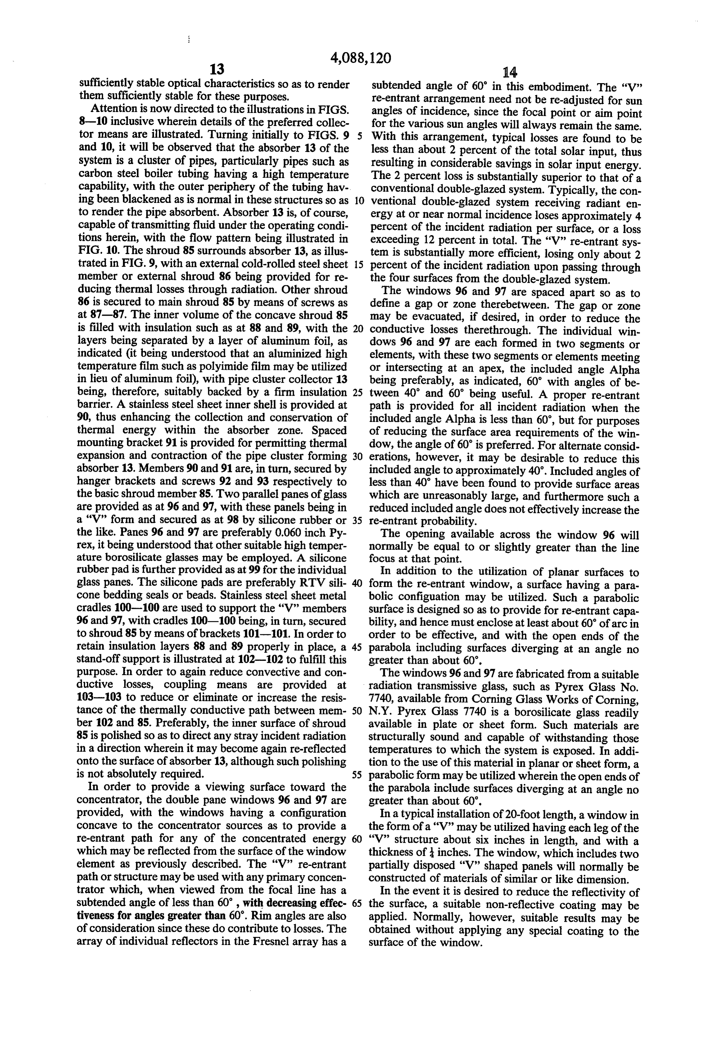
sufficiently stable optical characteristics so as to render subtended angle of 60' in this embodiment. The 'V' them sufficiently stable for these purposes. re-entrant arrangement need not be re-adjusted for sun Attention is now directed to the illustrations in FIGS. angles of incidence, since the focal point or aim point 8-10 inclusive wherein details of the preferred collec for the various sun angles will always remain the same. tor means are illustrated. Turning initially to FIGS. 9 With this arrangement, typical losses are found to be and 10, it will be observed that the absorber 13 of the less than about 2 percent of the total solar input, thus system is a cluster of pipes, particularly pipes such as resulting in considerable savings in solar input energy. carbon steel boiler tubing having a high temperature The 2 percent loss is substantially superior to that of a capability, with the outer periphery of the tubing hav conventional double-glazed system. Typically, the con ing been blackened as is normal in these structures so as 10 ventional double-glazed system receiving radiant en to render the pipe absorbent. Absorber 13 is, of course, ergy at or near normal incidence loses approximately 4 capable of transmitting fluid under the operating condi percent of the incident radiation per surface, or a loss tions herein, with the flow pattern being illustrated in exceeding 12 percent in total. The “V” re-entrant sys FIG. 10. The shroud 85 surrounds absorber 13, as illus tem is substantially more efficient, losing only about 2 trated in FIG. 9, with an external cold-rolled steel sheet 15 percent of the incident radiation upon passing through member or external shroud 86 being provided for re the four surfaces from the double-glazed system. ducing thermal losses through radiation. Other shroud The windows 96 and 97 are spaced apart so as to 86 is secured to main shroud 85 by means of screws as define a gap or Zone therebetween. The gap or zone at 87-87. The inner volume of the concave shroud 85 may be evacuated, if desired, in order to reduce the is filled with insulation such as at 88 and 89, with the 20 conductive losses therethrough. The individual win layers being separated by a layer of aluminum foil, as dows 96 and 97 are each formed in two segments or indicated (it being understood that an aluminized high elements, with these two segments or elements meeting temperature film such as polyimide film may be utilized or intersecting at an apex, the included angle Alpha in lieu of aluminum foil), with pipe cluster collector 13 being preferably, as indicated, 60 with angles of be being, therefore, suitably backed by a firm insulation 25 tween 40 and 60' being useful. A proper re-entrant barrier. A stainless steel sheet inner shell is provided at path is provided for all incident radiation when the 90, thus enhancing the collection and conservation of included angle Alpha is less than 60, but for purposes thermal energy within the absorber zone. Spaced of reducing the surface area requirements of the win mounting bracket 91 is provided for permitting thermal dow, the angle of 60 is preferred. For alternate consid expansion and contraction of the pipe cluster forming 30 erations, however, it may be desirable to reduce this absorber 13. Members 90 and 91 are, in turn, secured by included angle to approximately 40'. Included angles of hanger brackets and screws 92 and 93 respectively to less than 40 have been found to provide surface areas the basic shroud member 85. Two parallel panes of glass which are unreasonably large, and furthermore such a are provided as at 96 and 97, with these panels being in reduced included angle does not effectively increase the a 'V' form and secured as at 98 by silicone rubber or 35 re-entrant probability.
the like. Panes 96 and 97 are preferably 0.060 inch Py The opening available across the window 96 will rex, it being understood that other suitable high temper normally be equal to or slightly greater than the line ature borosilicate glasses may be employed. A silicone focus at that point.
rubber pad is further provided as at 99 for the individual In addition to the utilization of planar surfaces to glass panes. The silicone pads are preferably RTV sili form the re-entrant window, a surface having a para cone bedding seals or beads. Stainless steel sheet metal bolic configuation may be utilized. Such a parabolic cradles 100-100 are used to support the "V" members surface is designed so as to provide for re-entrant capa 96 and 97, with cradles 100-100 being, in turn, secured bility, and hence must enclose at least about 60' of arc in to shroud 85 by means of brackets 101-101. In order to order to be effective, and with the open ends of the retain insulation layers 88 and 89 properly in place, a 45 parabola including surfaces diverging at an angle no stand-off support is illustrated at 102-102 to fulfill this greater than about 60'.
purpose. In order to again reduce convective and con The windows 96 and 97 are fabricated from a suitable ductive losses, coupling means are provided at radiation transmissive glass, such as Pyrex Glass No. 103-103 to reduce or eliminate or increase the resis 7740, available from Corning Glass Works of Corning, tance of the thermally conductive path between mem 50 N.Y. Pyrex Glass 7740 is a borosilicate glass readily ber 102 and 85. Preferably, the inner surface of shroud available in plate or sheet form. Such materials are 85 is polished so as to direct any stray incident radiation structurally sound and capable of withstanding those in a direction wherein it may become again re-reflected temperatures to which the system is exposed. In addi onto the surface of absorber 13, although such polishing tion to the use of this material in planar or sheet form, a is not absolutely required. 55 parabolic form may be utilized wherein the open ends of In order to provide a viewing surface toward the the parabola include surfaces diverging at an angle no concentrator, the double pane windows 96 and 97 are greater than about 60'.
provided, with the windows having a configuration In a typical installation of 20-foot length, a window in concave to the concentrator sources as to provide a the form of a "V" may be utilized having each leg of the re-entrant path for any of the concentrated energy "V' structure about six inches in length, and with a which may be reflected from the surface of the window thickness of inches. The window, which includes two element as previously described. The "V" re-entrant partially disposed "V" shaped panels will normally be path or structure may be used with any primary concen constructed of materials of similar or like dimension. trator which, when viewed from the focal line has a In the event it is desired to reduce the reflectivity of subtended angle of less than 60, with decreasing effec 65 the surface, a suitable non-reflective coating may be tiveness for angles greater than 60'. Rim angles are also applied. Normally, however, suitable results may be of consideration since these do contribute to losses. The obtained without applying any special coating to the array of individual reflectors in the Fresnel array has a surface of the window.
Page 18
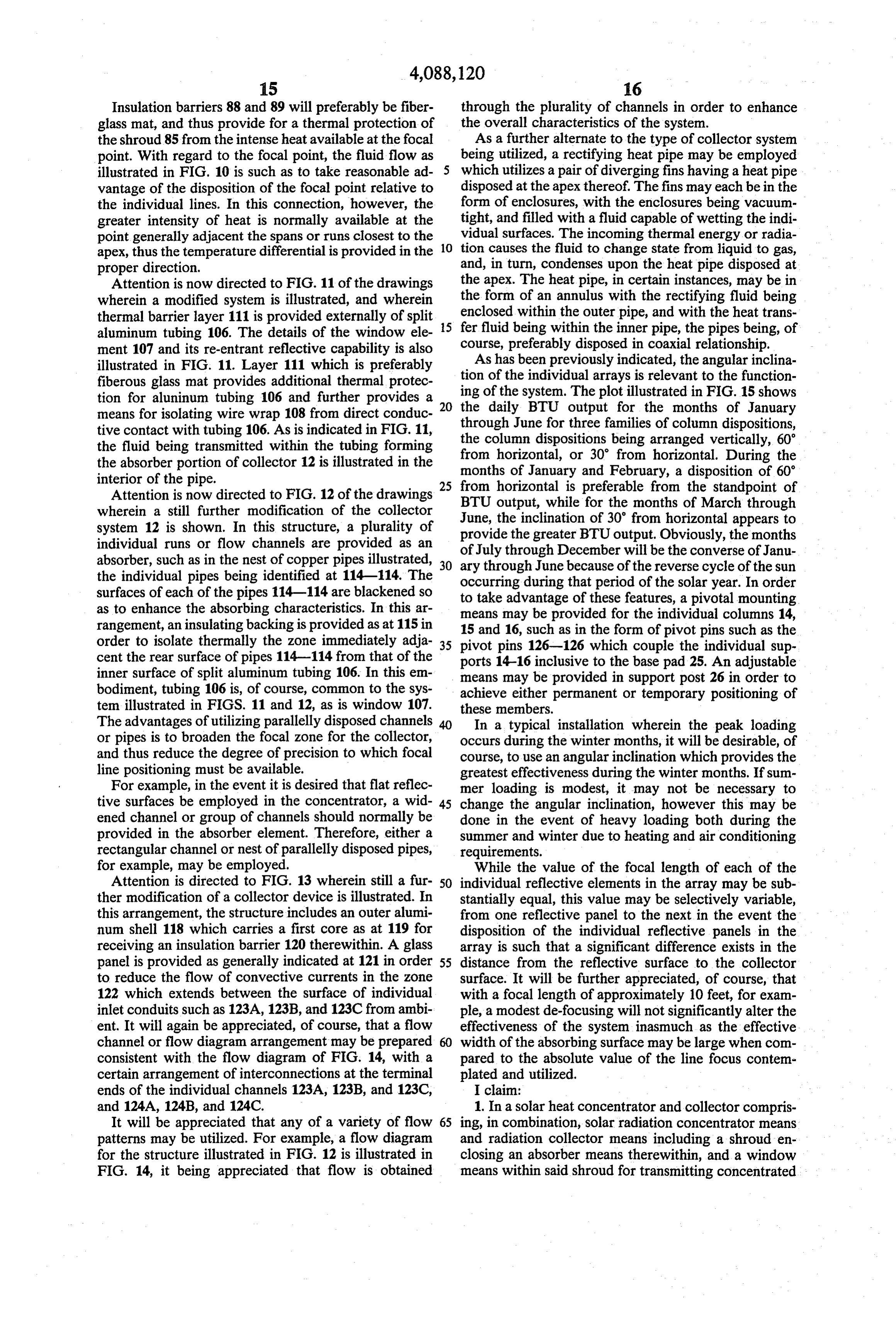
Insulation barriers 88 and 89 will preferably be fiber through the plurality of channels in order to enhance glass mat, and thus provide for a thermal protection of the overall characteristics of the system. the shroud 85 from the intense heat available at the focal As a further alternate to the type of collector system point. With regard to the focal point, the fluid flow as being utilized, a rectifying heat pipe may be employed illustrated in FIG. 10 is such as to take reasonable ad 5 which utilizes a pair of diverging fins having a heat pipe vantage of the disposition of the focal point relative to disposed at the apex thereof. The fins may each be in the the individual lines. In this connection, however, the form of enclosures, with the enclosures being vacuum greater intensity of heat is normally available at the tight, and filled with a fluid capable of wetting the indi point generally adjacent the spans or runs closest to the vidual surfaces. The incoming thermal energy or radia apex, thus the temperature differential is provided in the 10 tion causes the fluid to change state from liquid to gas, proper direction. and, in turn, condenses upon the heat pipe disposed at Attention is now directed to FIG. 11 of the drawings the apex. The heat pipe, in certain instances, may be in wherein a modified system is illustrated, and wherein the form of an annulus with the rectifying fluid being thermal barrier layer 111 is provided externally of split 15 enclosed within the outer pipe, and with the heat trans aluminum tubing 106. The details of the window ele course, fer fluid being within the inner pipe, the pipes being, of ment 107 and its re-entrant reflective capability is also preferably disposed in coaxial relationship. illustrated in FIG. 11. Layer 111 which is preferably As has been previously indicated, the angular inclina fiberous glass mat provides additional thermal protec tionofofthe the individual arrays is relevant to the function tion for aluminum tubing 106 and further provides a 20 ing the daily system. The plot illustrated in FIG. 15 shows
BTU output for the months of January means for isolating wire wrap 108 from direct conduc tive contact with tubing 106. As is indicated in FIG. 11, through June for three families of column dispositions, the column dispositions being arranged vertically, 60' the fluid being transmitted within the tubing forming from the absorber portion of collector 12 is illustrated in the monthshorizontal, of January or 30 from horizontal. During the and February, a disposition of 60' interior of the pipe.
Attention is now directed to FIG. 12 of the drawings from horizontal is preferable from the standpoint of
wherein a still further modification of the collector BTU output, while for the months of March through system 12 is shown. In this structure, a plurality of June, provide the inclination of 30' from horizontal appears to the greater BTU output. Obviously, the months individual runs or flow channels are provided as an of July through absorber, such as in the nest of copper pipes illustrated, 30 ary through JuneDecember will be the converse of Janu the individual pipes being identified at 114-114. The occurring during that periodthe because of reverse cycle of the sun of the solar year. In order surfaces of each of the pipes 114-114 are blackened so to take advantage of these features, a pivotal mounting as to enhance the absorbing characteristics. In this ar rangement, an insulating backing is provided as at 115 in means
may be provided for the individual columns 14, 16, such as in the form of pivot pins such as the order to isolate thermally the zone immediately adja 35 pivot pins 126-126 which couple the individual sup cent the rear surface of pipes 114-114 from that of the ports 14-16 inclusive to the base pad 25. An adjustable inner surface of split aluminum tubing 106. In this em means may be provided in support post 26 in order to bodiment, tubing 106 is, of course, common to the sys achieve either permanent or temporary positioning of tem illustrated in FIGS. 11 and 12, as is window 107. these members.
The advantages of utilizing parallelly disposed channels In a typical installation wherein the peak loading or pipes is to broaden the focal zone for the collector, occurs during the winter months, it will be desirable, of and thus reduce the degree of precision to which focal course, to use an angular inclination which provides the line positioning must be available. greatest effectiveness during the winter months. If sum For example, in the event it is desired that flat reflec mer loading is modest, it may not be necessary to tive surfaces be employed in the concentrator, a wid 45 change the angular inclination, however this may be ened channel or group of channels should normally be done in the event of heavy loading both during the provided in the absorber element. Therefore, either a summer and winter due to heating and air conditioning rectangular channel or nest of parallelly disposed pipes, requirements.
for example, may be employed. While the value of the focal length of each of the Attention is directed to FIG. 13 wherein still a fur 50 individual reflective elements in the array may be sub ther modification of a collector device is illustrated. In stantially equal, this value may be selectively variable, this arrangement, the structure includes an outer alumi from one reflective panel to the next in the event the num shell 118 which carries a first core as at 119 for disposition of the individual reflective panels in the receiving an insulation barrier 120 therewithin. A glass array is such that a significant difference exists in the panel is provided as generally indicated at 121 in order 55 distance from the reflective surface to the collector to reduce the flow of convective currents in the zone surface. It will be further appreciated, of course, that 122 which extends between the surface of individual with a focal length of approximately 10 feet, for exam inlet conduits such as 123A, 123B, and 123C from ambi ple, a modest de-focusing will not significantly alter the ent. It will again be appreciated, of course, that a flow effectiveness of the system inasmuch as the effective channel or flow diagram arrangement may be prepared width of the absorbing surface may be large when com consistent with the flow diagram of FIG. 14, with a pared to the absolute value of the line focus contem certain arrangement of interconnections at the terminal plated and utilized.
ends of the individual channels 123A, 123B, and 123C, I claim:
and 124A, 124B, and 124C. 1. In a solar heat concentrator and collector compris It will be appreciated that any of a variety of flow 65 ing, in combination, solar radiation concentrator means patterns may be utilized. For example, a flow diagram and radiation collector means including a shroud en for the structure illustrated in FIG. 12 is illustrated in closing an absorber means therewithin, and a window FIG. 14, it being appreciated that flow is obtained means within said shroud for transmitting concentrated
Page 19
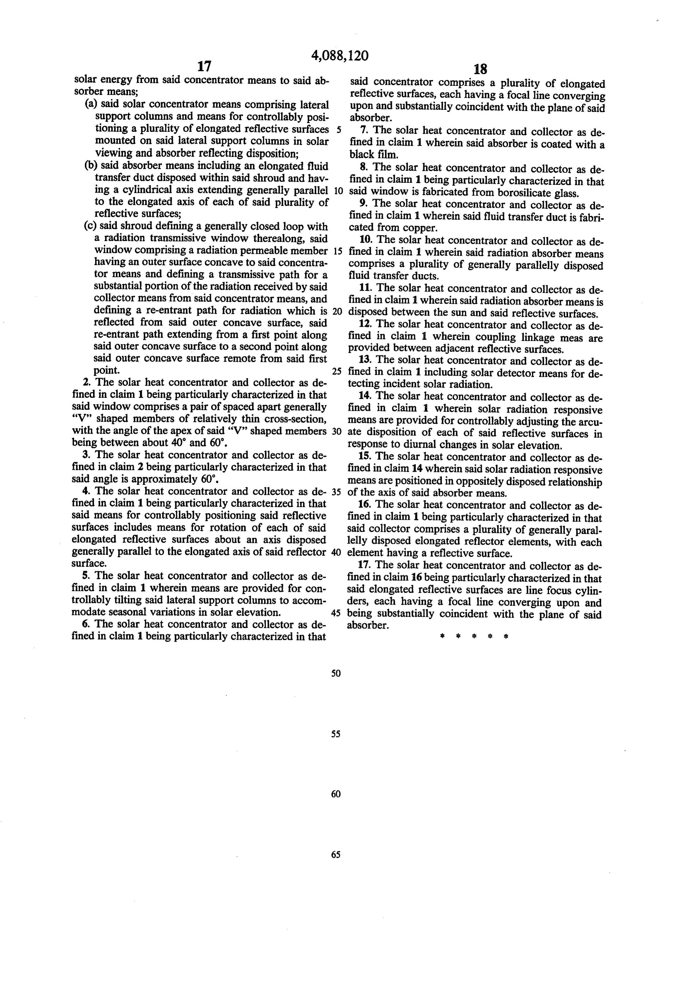
solar energy from said concentrator means to said ab said concentrator comprises a plurality of elongated sorber means; reflective surfaces, each having a focal line converging (a) said solar concentrator means comprising lateral upon and substantially coincident with the plane of said support columns and means for controllably posi absorber.
tioning a plurality of elongated reflective surfaces 5 7. The solar heat concentrator and collector as de mounted on said lateral support columns in solar fined in claim 1 wherein said absorber is coated with a viewing and absorber reflecting disposition; black film.
(b) said absorber means including an elongated fluid 8. The solar heat concentrator and collector as de transfer duct disposed within said shroud and hav fined in claim 1 being particularly characterized in that ing a cylindrical axis extending generally parallel 10 said window is fabricated from borosilicate glass. to the elongated axis of each of said plurality of 9. The solar heat concentrator and collector as de reflective surfaces; fined in claim 1 wherein said fluid transfer duct is fabri (c) said shroud defining a generally closed loop with cated from copper.
a radiation transmissive window therealong, said 10. The solar heat concentrator and collector as de window comprising a radiation permeable member 15 fined in claim 1 wherein said radiation absorber means having an outer surface concave to said concentra comprises a plurality of generally parallelly disposed tor means and defining a transmissive path for a fluid transfer ducts.
substantial portion of the radiation received by said 11. The solar heat concentrator and collector as de collector means from said concentrator means, and fined in claim 1 wherein said radiation absorber means is defining a re-entrant path for radiation which is disposed between the sun and said reflective surfaces. reflected from said outer concave surface, said 12. The solar heat concentrator and collector as de re-entrant path extending from a first point along fined in claim 1 wherein coupling linkage meas are said outer concave surface to a second point along provided between adjacent reflective surfaces. said outer concave surface remote from said first 13. The solar heat concentrator and collector as de point. 25 fined in claim 1 including solar detector means for de 2. The solar heat concentrator and collector as de tecting incident solar radiation.
fined in claim 1 being particularly characterized in that 14. The solar heat concentrator and collector as de said window comprises a pair of spaced apart generally fined in claim 1 wherein solar radiation responsive “V' shaped members of relatively thin cross-section, means are provided for controllably adjusting the arcu with the angle of the apex of said "V" shaped members 30 ate disposition of each of said reflective surfaces in being between about 40' and 60'. response to diurnal changes in solar elevation. 3. The solar heat concentrator and collector as de 15. The solar heat concentrator and collector as de fined in claim 2 being particularly characterized in that fined in claim 14 wherein said solar radiation responsive said angle is approximately 60'. means are positioned in oppositely disposed relationship 4. The solar heat concentrator and collector as de 35 of the axis of said absorber means.
fined in claim 1 being particularly characterized in that 16. The solar heat concentrator and collector as de said means for controllably positioning said reflective fined in claim 1 being particularly characterized in that surfaces includes means for rotation of each of said said collector comprises a plurality of generally paral elongated reflective surfaces about an axis disposed lelly disposed elongated reflector elements, with each generally parallel to the elongated axis of said reflector element having a reflective surface. surface. 17. The solar heat concentrator and collector as de 5. The solar heat concentrator and collector as de fined in claim 16 being particularly characterized in that fined in claim 1 wherein means are provided for con said elongated reflective surfaces are line focus cylin trollably tilting said lateral support columns to accom ders, each having a focal line converging upon and modate seasonal variations in solar elevation. 45 being substantially coincident with the plane of said 6. The solar heat concentrator and collector as de absorber.
fined in claim 1 being particularly characterized in that 2: sk s :
Page 20
UNITED STATES PATENT AND TRADEMARK OFFICE
CERTIFICATE OF CORRECTION
NVENTOR(S) : Donald E. Anderson
It is certified that error appears in the above-identified patent and that said Letters Patent are hereby Corrected as shown below:
Column 8, lines 32-33 "focused" should read -- forced --. Column l3, line l7, "Other" should read -- Outer --.
Line 59, "sources" should read -- source so -- .
signed and sealed this
Twelfth Day of September 1978
(SEAL
Attesting Officer Commissioner of Patents and Trademarks

Provenance
- Collection
- Cited prior art
- Original PDF
- patentimages.storage.googleapis.com →
- Filed
- 1976-09-02
- Pages
- 20
- Method
- pdftotext (the PDF's own text layer) + pdftoppm 300dpi page scans
- Source
- Google Patents bibliographic record
- Granted
- 1978-05-09
- Inventors
- Donald E. Anderson; SUNTEC SYSTEMS Inc
- Transcribed from
- patentimages.storage.googleapis.com →