patent · US5882434
Solar concentrator having an offset parabolic configuration
16 March 1999
Page 1 — bibliographic record
United States Patent (19) 11 Patent Number: 5,882,434 Horne (45) Date of Patent: Mar 16, 1999 54). SOLAR CONCENTRATOR HAVING AN Primary Examiner Mark Chapman OFFSET PARABOLIC CONFIGURATION Attorney, Agent, or Firm Jensen & Puntigam, P.S. 75 Inventor: William E. Horne, Renton, Wash. 57 ABSTRACT 73 Assignee: United Solar Technologies, Inc., The Solar concentrator System includes a generally Olympia, Wash. parabolic-shaped primary reflector having a flat region at the center thereof, So that the focus of the primary reflector is a 21 Appl. No.: 725,645 ring about the center axis of the reflector, in the plane of the 22 Filed: Oct. 15, 1996 rim thereof. A receiver, in the shape of an inverted, truncated cone, is positioned So that the peripheral Surface of the 51 Int. C. ------- --- --- ------------- --- HOL 25/00; HO2N 6/00; receiver is approximately coincident with the ring focus.
F24J 2/12 Solar cells are positioned in lines on the peripheral Surface 52 U.S. Cl. .......................... 136/246; 126/686; 126/690; of the receiver. Prefilter tubular secondary concentrator 126/694 elements are positioned just in front of the lines of Solar 58 Field of Search ............................. 136/246; 126/686, cells, providing an additional focusing capability and 126/690, 694 improving the concentration of the Solar rays, while being 56) References Cited spaced sufficiently that the unilluminated areas between the lines of Solar cells can accommodate electrical interconnec
4,240,692 12/1980 Winston .................................. 136/246 5,269,851 12/1993 Horne ...................................... 136/248 12 Claims, 7 Drawing Sheets
Page 2
Drawing sheet — no readable text.
Page 3
Drawing sheet — no readable text.
Page 4
Drawing sheet — no readable text.
Page 5
Drawing sheet — no readable text.
Page 6
Drawing sheet — no readable text.
Page 7
Drawing sheet — no readable text.
Page 8
Drawing sheet — no readable text.
Page 9
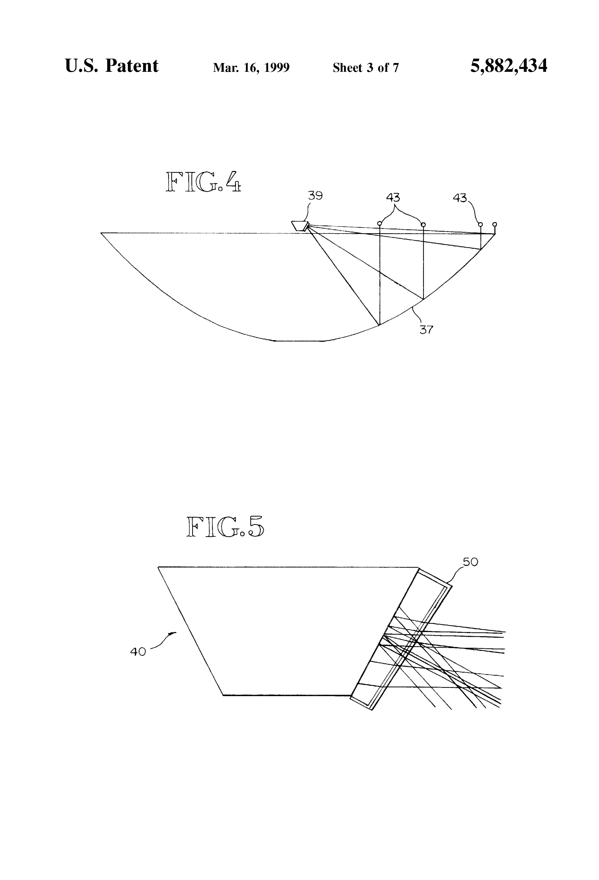
SOLAR CONCENTRATOR HAVING AN FIG. 5 is an elevational view showing the receiver and OFFSET PARABOLIC CONFIGURATION one prefilter portion of the concentrator System.
TECHNICAL FIELD
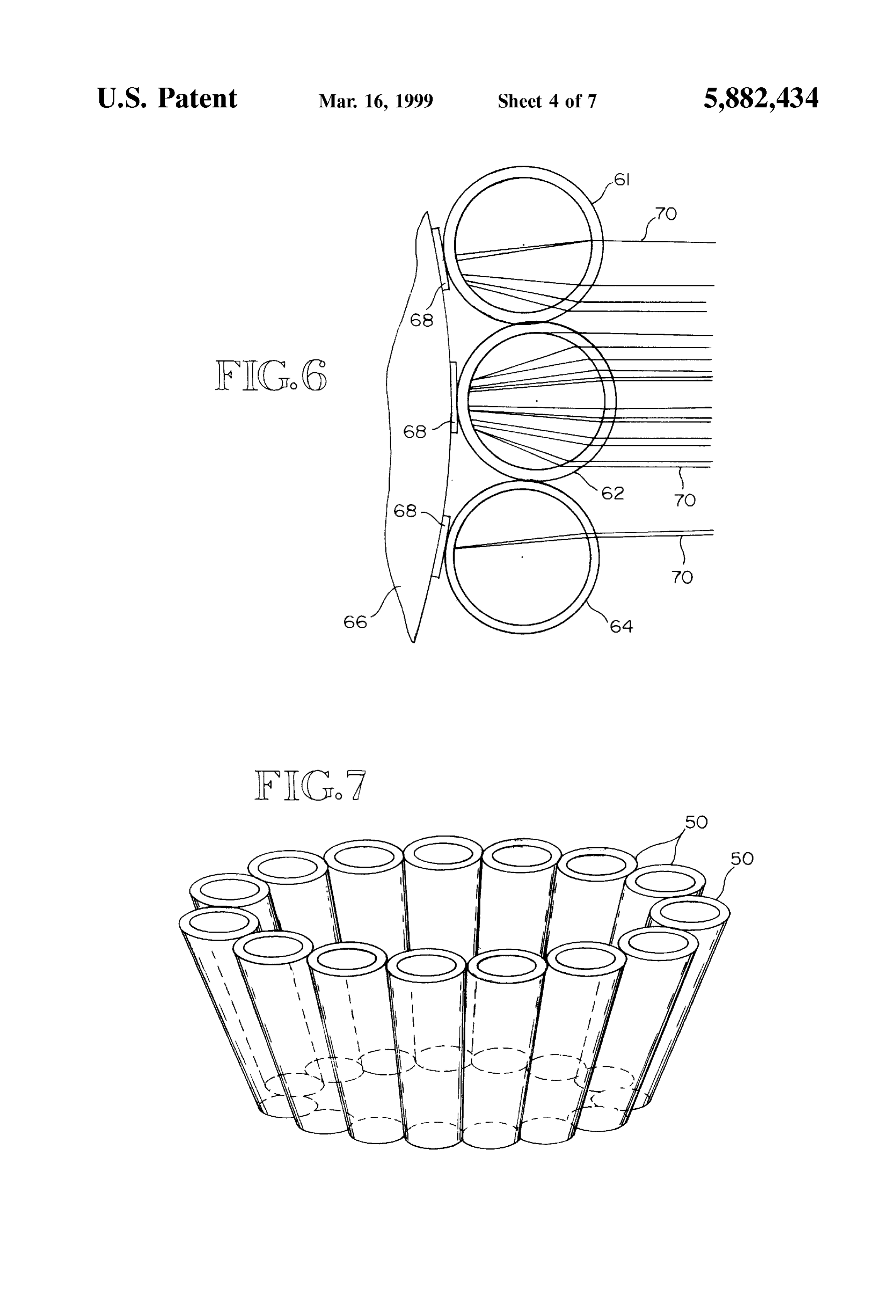
FIG. 6 is a croSS-Sectional view showing a portion of the receiver/prefilter portion of the concentrator System.
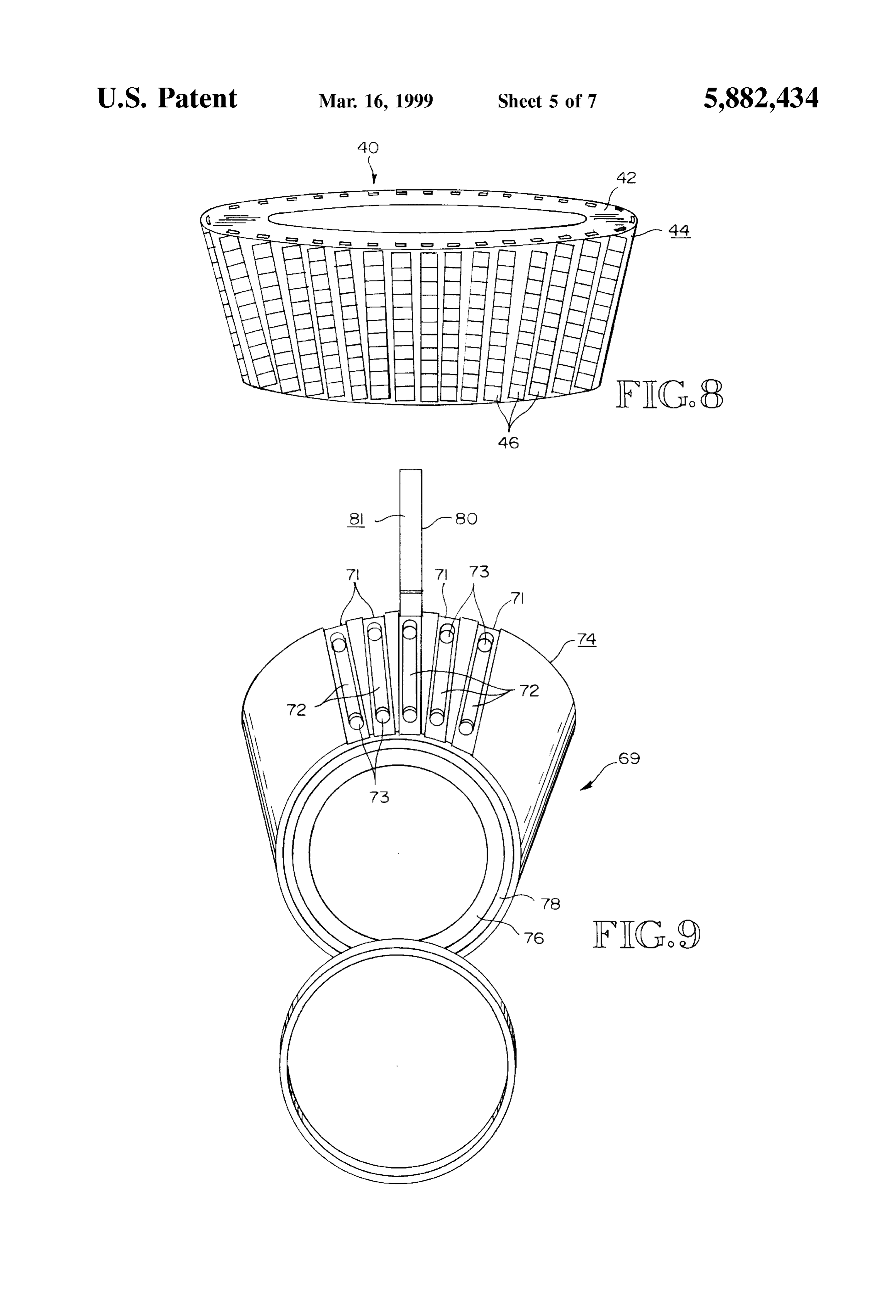
This invention relates generally to the field of Solar FIG. 7 is an elevational view showing a prefilter portion concentrators and more specifically concerns a particular of a concentrator System of the present invention. Solar concentrator configuration. FIG. 8 is an elevational view showing the Solar cell BACKGROUND OF THE INVENTION mounting arrangement on the receiver of the present inven tion.
In the past, Solar concentrators have typically been con FIG. 9 is a perspective view (partially disassembled) figured to produce either a point focus or a line focus for the showing the cooling Structure of the receiver of the present impinging Solar rayS. Line focus concentrators are in the invention.
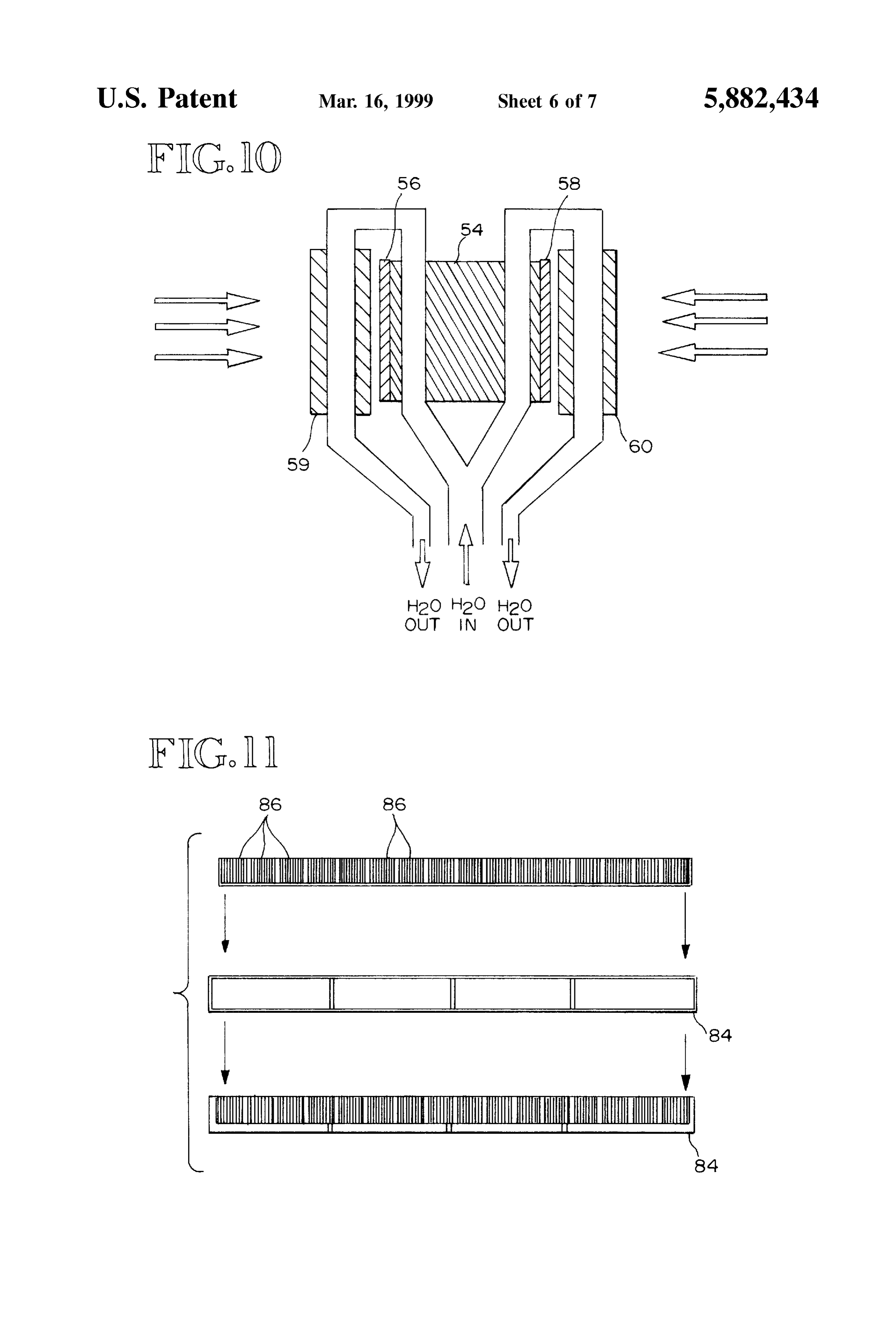
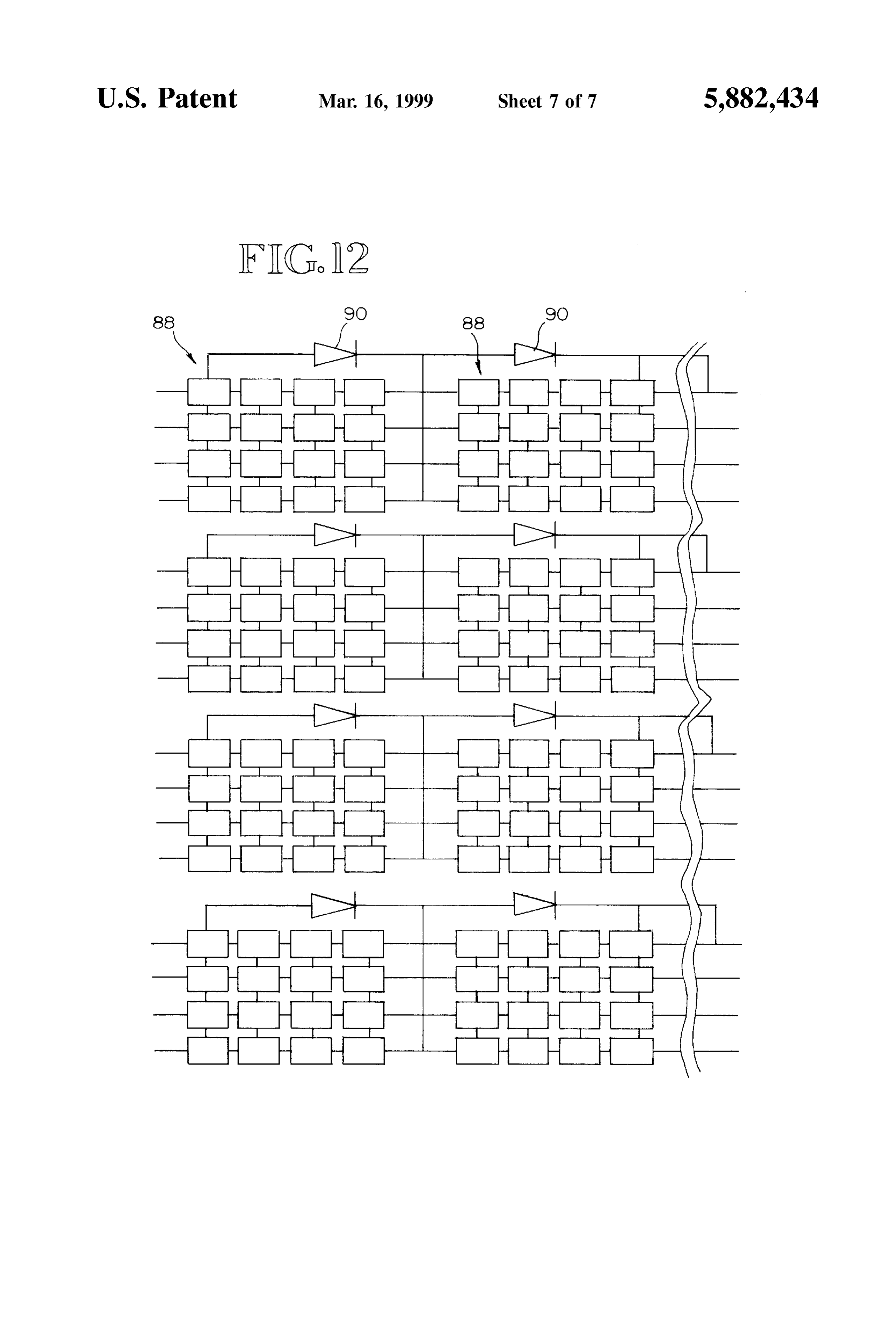
form of an elongated trough, with the line focus basically FIG. 10 is a cross-sectional view of the receiver of the being in a plane which includes the opposing longitudinal present invention, illustrating the coolant flow in the
edges of the trough. Point focus concentrators, on the other receiver.
hand, have been dish-shaped, typically parabolic in croSS FIG. 11 is a view showing the structure for mounting the Section.
Solar cells onto the Surface of the receiver.
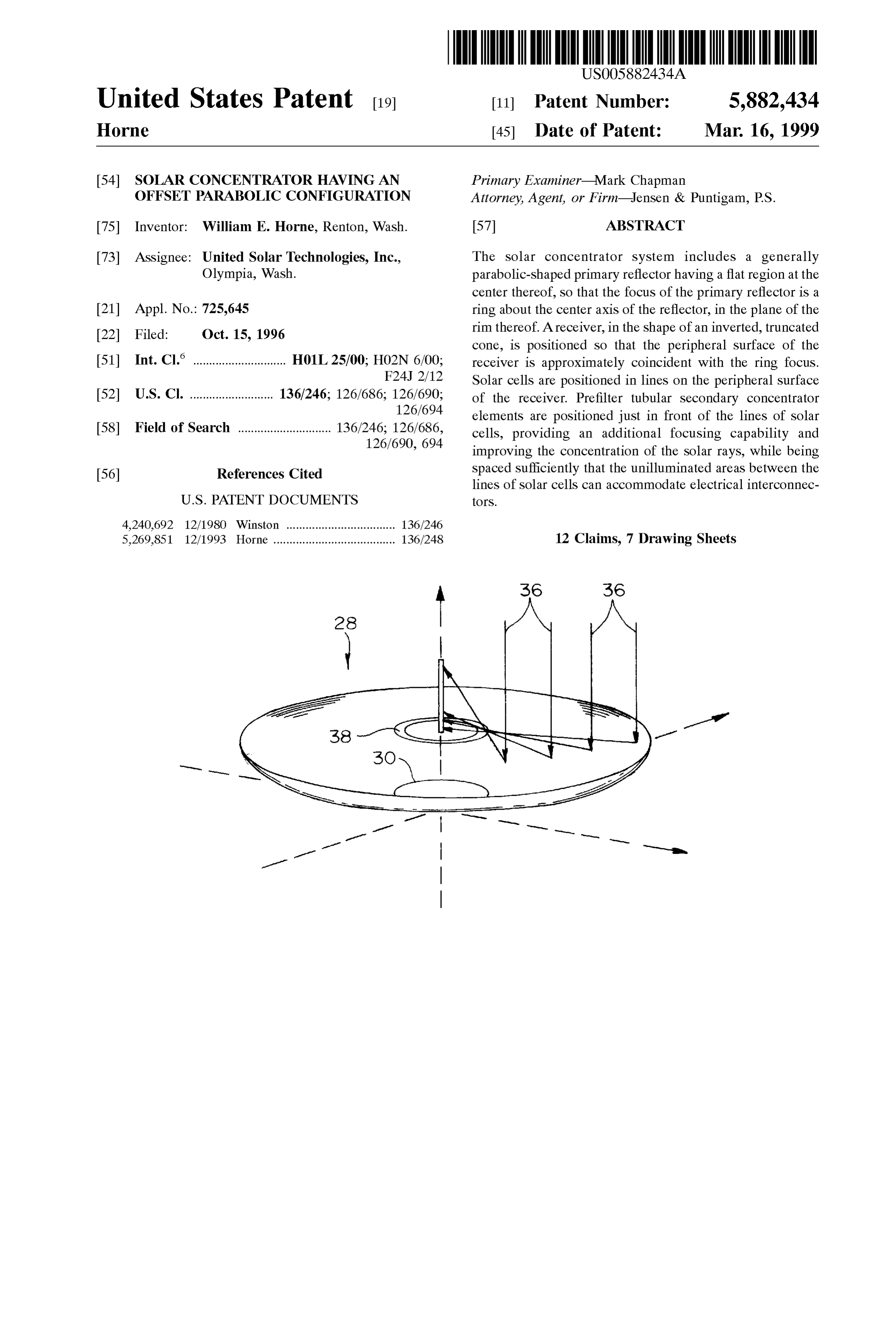
At the focal point of the point focus concentrators will FIG. 12 is a view representing the connection of the Solar typically be either a boiler assembly, in which a Selected cells on the receiver of the System of the present invention. liquid is heated to high temperatures by the Solar rays reflected and focused from the Surface of the concentrator or, BEST MODE FOR CARRYING OUT THE in Some cases, a Solar cell assembly, Such as shown in U.S. INVENTION Pat. No. 5,269,851, which is assigned to the assignee of the FIG. 1 shows a complete Solar concentrator System of the present invention, the contents of which are hereby incor 25 present invention, including a primary concentrator 12, a porated by reference. Typically, Such concentrators have a receiver 14 which is positioned generally at the focus of the concentration ratio in the range of 500:1, which may be primary concentrator 12 and includes a base plate 13 and top increased Somewhat by the use of a prefilter/Secondary plate 15, a plurality of Solar cells 16-16 mounted on a concentrator positioned in front of the Solar cells, which surface of the receiver 14, and prefilter elements 18-18 adds an additional focusing capability for the concentrator which are positioned just in front of each of the Solar cells and has the further benefit of removing some of the heat 16-16. Solar rays shown at 17-17 reflect from the primary from the Solar cells when liquid is moved therethrough. concentrator 12 onto the prefilter elements 18. Each prefilter While the above-described concentrator structure cer 18 functions both as a Secondary concentrator and as a tainly has Some advantages over other Solar energy Systems cooling element, by use of liquid which is moved through in efficiency and cost, it is desirable that efficiency be still 35 internal channels in the prefilter as well as the receiver. The further increased, So as to make Solar energy competitive heated prefilter liquid can then be used as an additional with other forms of energy, particularly petroleum. In energy Source.
addition, the primary concentrator portions of Solar concen The primary concentrator 12 can have a variety of reflec trator Systems have usually required "optical quality’ fin tive Surfaces, including for example glass or other highly ishes for their reflective Surfaces to maintain System effi 40 reflective Surface. The primary concentrator is generally ciency. Such optical-quality finishes contribute significantly parabolic, but includes a portion thereof which has a par to the expense of Such concentrator Systems. ticular configuration other than parabolic, which distin SUMMARY OF THE INVENTION guishes it from other concentrator Systems. The primary concentrator of the present invention is configured in what
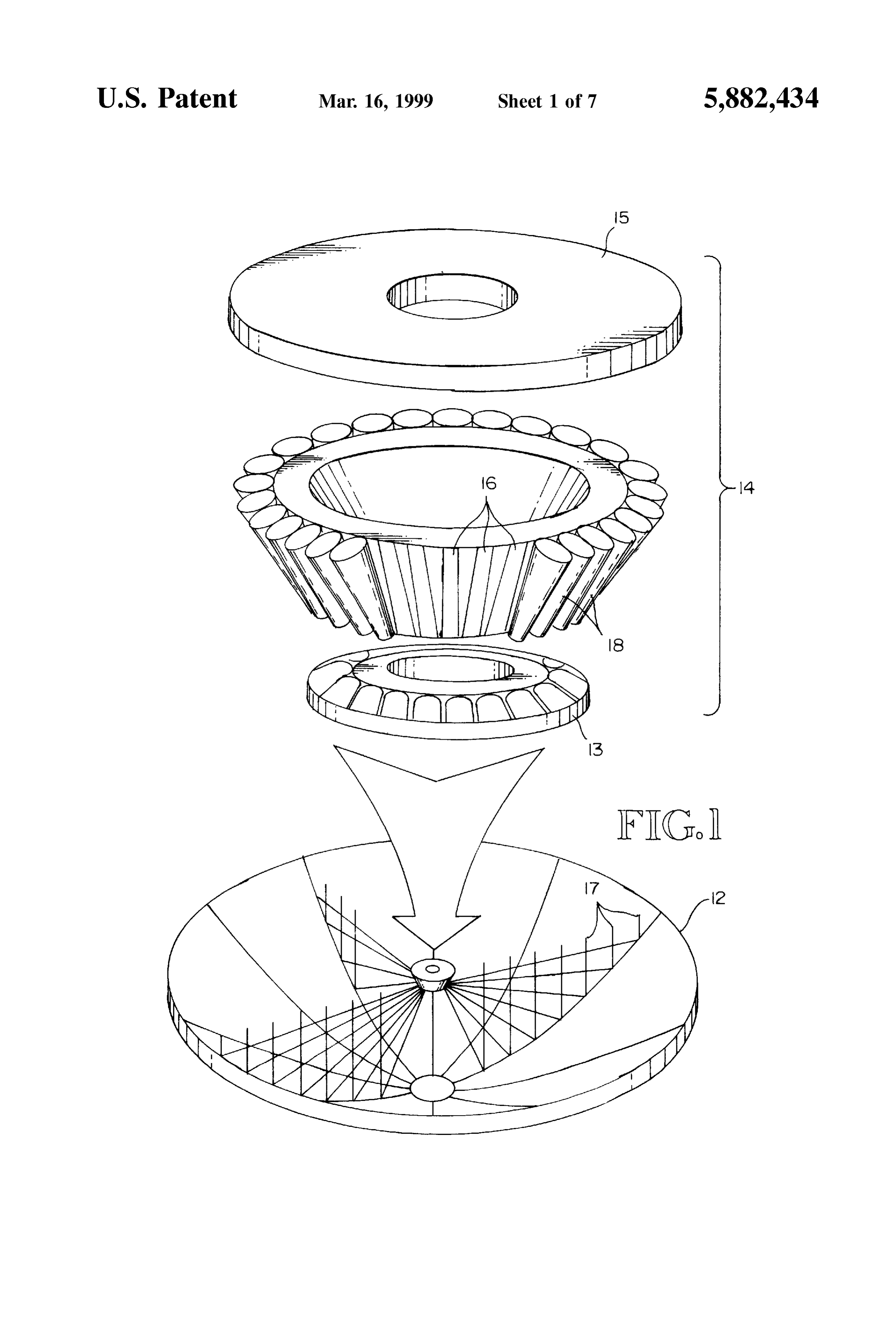
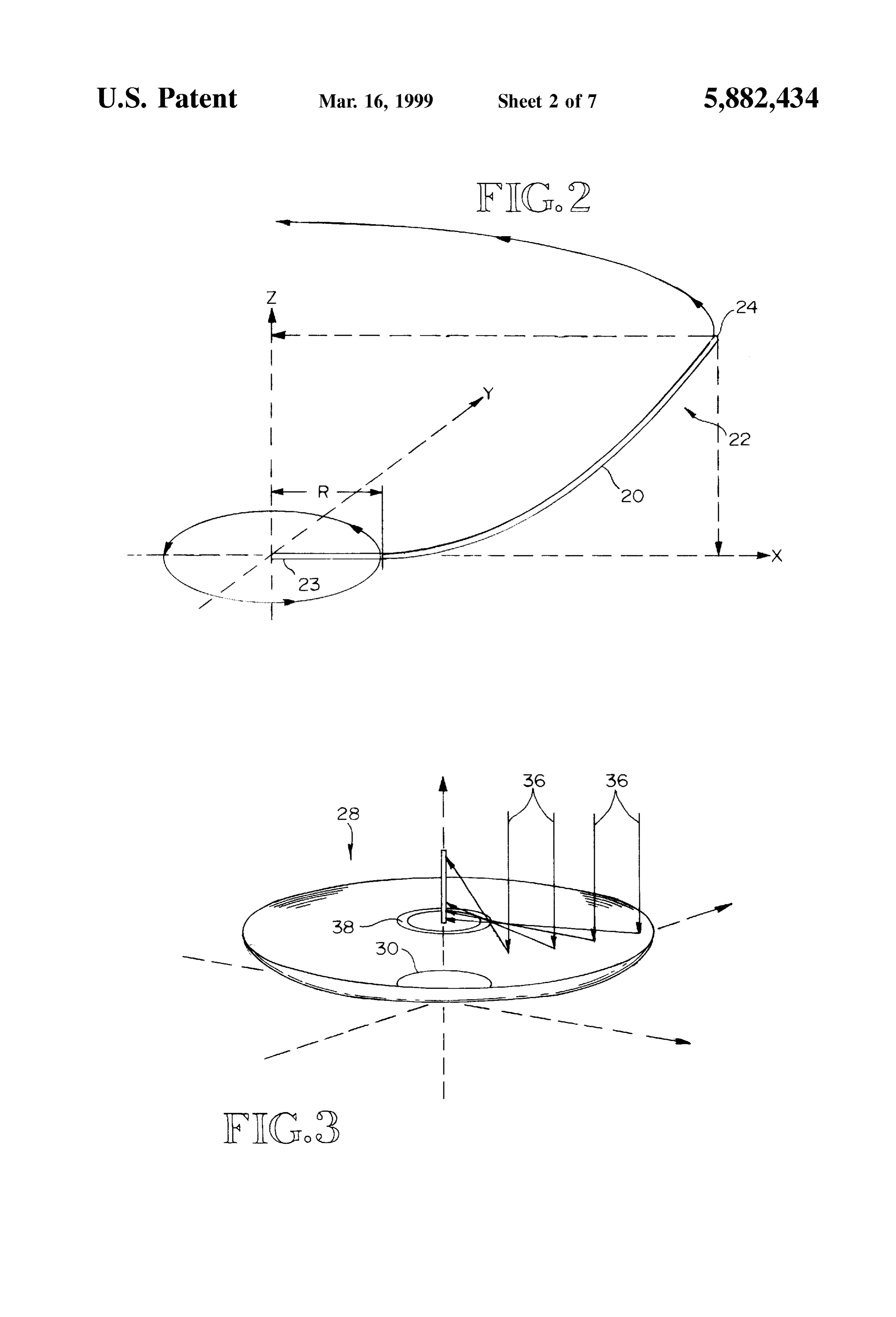
Accordingly, the present invention includes a Solar con 45 is referred to as an offset parabola, i.e. the parabolic curve centrator System for focusing Solar rays incident thereon to begins at a Selected distance or radius from the center axis a receiver portion, including: a parabolic reflector having a of the concentrator. From the center axis to this radius the reflective Surface which is generally flat from a center axis Surface of the concentrator is flat. This is illustrated in FIGS. of the reflector to a line which extends about the center axis, 2-4.
located a Selected distance from the center axis and from 50 FIG. 2 shows a cross-sectional outline of a portion 20 of there is generally parabolic to a rim of the reflector, Such that the concentrator 22, with conventional X-Y-Z coordinates. the focus of the reflector is on a ring Surface Surrounding the Rotation of portion 20 about the center axis of the concen center axis, and a receiver having a plurality of Solar cells trator (the Z axis in FIG. 2) will produce the concentrator arranged on a peripheral Surface thereof, the Surface being configuration of the present invention. The concentrator generally coincident with the ring Surface focus of the 55 surface thus extends outwardly from the Zero point 23 (the reflector. center axis point) along the X-axis for a distance R, at which BRIEF DESCRIPTION OF THE DRAWINGS point (actually a circle around the centered axis) the Surface of the concentrator curves upwardly in a generally parabolic
FIG. 1 is a Schematic diagram showing the complete configuration. In one Specific example, where the diameter concentrator System of the present invention. 60 of the primary concentrator 12 at its rim 24 is 84 inches, FIG. 2 is a simplified diagram showing the configuration distance R will be approximately 3 inches. A range of R for of the concentrator of the present invention. various reflector diameters might be 2-6 inches, for FIG. 3 is a diagram showing in more detail the concen example.
trator configuration of FIG. 2, including the focus of the A more complete view of the concentrator is shown in COncentrator. 65 FIG.3 at 28, with the parabolic curvature portion beginning FIG. 4 is a simplified elevational view of the concentrator along a circular line 30 which is removed from the central system of FIG. 2. Z-axis 32 by a Selected distance.
Page 10
Drawing sheet — no readable text.
Page 11
S 6 light rays 70-70 onto the Solar cells. This additional at the dividing point between the slots 71 and the deeper concentration factor can be as high as 3:1 for the configu coolant channels 72.
ration shown (higher for larger diameter tubular elements In the respective end (top and bottom) surfaces 74 and 76 and/or higher index fluids), which will thus raise, for of the substrate are annular plenum chambers 78. There is no example, an existing concentration ratio of 500:1 for a communication between the plenum chambers 78 and the primary concentrator to a System concentration ratio of slots 71-71. However, at the respective ends of each 1500:1. This is advantageous, Since it permits the use of a coolant channel 72, a Small opening 73, typically made by primary concentrator which does not have an optical-quality drilling, extends through the remaining Substrate to the reflective Surface, as part of a high concentration, and hence plenum chamber at that end. There is hence fluid commu high efficiency, System. The primary concentrator, Since its nication between each of the coolant channels 72 and the reflective Surface need not be optical quality, can thus be plenum chambers at the respective ends of the Substrate. Significantly leSS expensive than otherwise. In one embodiment, each end of each coolant channel is One of the advantages of combining a tubular prefilter in fluid communication with the plenum chamber adjacent arrangement with an offset parabola concentrator is that the thereto, the plenum chamber being continuous, while in combination can take advantage of the full concentrating 15 another embodiment, the plenum chamber is not continuous power of the primary concentrator for the parabolically but takes the form of Successive Segments arranged So that directed rays, i.e. those rays which are reflected off the one end of each coolant channel is in fluid communication Surface of the primary concentrator. The wide angle con via a plenum Segment to the adjacent end of the previous centration of the incident rays is accomplished by the channel and the other end of the channel is in fluid com primary concentrator onto a ring about the center axis of the munication via a plenum Segment to the adjacent end of the concentrator. The height of the ring is determined by the Successive channel, thus creating a Serpentine path of cool total error of the reflected beam. The Secondary concentra ant through the channels and the plenum Segments. In both tion is accomplished portion by portion around the ring embodiments, the coolant channels and the plenum cham focus, and each tubular Secondary focusing element need bers provide a passageway for movement of cooling fluid only accommodate a relatively Small angular portion of the 25 through the Substrate of the receiver, carrying away heat reflected rays. The total focusing effort thus is accomplished generated by the Solar cells.
in two Steps, by an initial Single concentrator in combination Lastly, slot covers 80-80 are configured so as to mate with a large plurality of Secondary concentrator elements. with the slots 71-71 which are milled into the Substrate, The overall height of the secondarily focused rays on the resting against the lip between the slots and the channels and Solar cells depends upon Several factors, including the thereby forming enclosed coolant channels in the Substrate. angular distribution of the Solar rays, errors in the System The slot covers are elongated flat members which, when in pointing mechanism (relative to the Sun), deviation in the place, have an upper Surface which is in the same plane as Surface of the reflector from a true parabolic shape, and the exterior Surface of the receiver. Slot cover 80 in FIG. 9 quality (roughness) of the reflector. 35 is shown against its associated Slot. AS mentioned above, the prefilter Secondary focusing The fluid must flow in sufficient volume through the arrangement permits the use of low-cost primary reflectors, channels to carry away the required amount of heat gener particularly the use of lower quality reflective Surfaces, ated by the Solar cells, and there must in addition be while Still maintaining a relatively high concentration So that Sufficient heat coupling between the fluid and the Substrate the System is efficient and competitive. Effective competi 40 to allow transfer of thermal energy to the fluid when there is tion with other energy Sources, notably petroleum, remains only a Small temperature difference between the Substrate an extremely important factor in Solar energy. and the fluid. For the configuration shown, with the coolant The receiver construction and configuration is shown in channels in the individual fluid prefilter tubes, the flow rate FIGS. 8 and 9. AS indicated above, the receiver in the through each prefilter tube need only be on the order of embodiment shown is generally in the form of a truncated 45 0.018 gallons per minute.
cone. While the receiver could have other configurations, a With Such a low flow rate, the cross-sectional area of the truncated cone shape has the advantage of providing a stable individual coolant channels must be relatively Small So as to mounting element for Solar cells, while permitting the cap give a Sufficiently high flow velocity to ensure a low enough ture of a greater number of Solar rays in the same vertical heat transfer coefficient for adequate cooling of the Solar distance than would be accomplished by a cylindrical 50 cells. For a temperature drop on the order of 5 C. between receiver. the Substrate and the fluid, a channel cross-sectional area FIG. 9 shows the details of the receiver Substrate con will be approximately 0.01.
struction. In the embodiment shown, the Substrate 69 is The individual Solar cells, in a String arrangement, are copper and has a plurality of longitudinal slots 71-71 attached to the exposed surface 81 of slot covers 80. In the which are milled into the Substrate around the entire periph 55 embodiment shown, a total of 32 slot covers are present ery thereof, one for each Solar cell strip. The slots extend for around the periphery of the receiver, with each slot cover 80 the complete height of the receiver. In one embodiment, the forming a base for one string of 16 solar cells. FIG. 11 Substrate is 1-inch thick and the slots are milled approxi illustrates one string (linear array) of 16 solar cells 86-86. mately /8-inch deep into the Substrate. Individual coolant The array in the embodiment shown is 3.15 inches long, channels 72-72 are then milled further into the Substrate 60 using Solar cells having a 0.5 centimeterx0.5 centimeter along the bottom of each slot 71. The coolant channels active area. The array includes an alumina Substrate 84 on 72-72, however, do not extend all the way to the respective which the Solar cells are mounted. Metallization on the top and bottom Surfaces of the receiver. Approximately ys alumina Substrate 84 is patterned So that the back contacts of inch of Substrate remains at the respective ends of the four adjacent cells are connected in parallel, thereby pro coolant channels. In the embodiment shown, the coolant 65 ducing four groups of Solar cells, with the cells in each group channels 72-72 are somewhat narrower than the slots 71 being in parallel to the other cells in that group. The alumina and approximately 4-inch deeper, which leaves a narrow lip substrate in FIG. 11 is an electrical insulator, but has good
Page 12
thermal conductivity, with a coefficient of thermal expansion the reflector to a circular line about the center axis which is similar to the particular GaAS Solar cells used in the which is located a Selected distance from the center axis embodiment shown. The matching coefficients of thermal and from there is parabolic to a rim of the reflector, expansion between the Solar cells and the Substrate is Such that the focus of the reflector is on a ring Sur important in order to avoid possible fatigue failure of the rounding the center axis, wherein the ring is in the bonds between the Solar cells and the substrate, which might vicinity of the plane of the rim of the reflector; and otherwise occur because of the continuous thermal cycling a receiver having a plurality of Solar cells arranged on a of the Solar cell array due to Successive periods of illumi peripheral Surface thereof, the Surface being generally nation and darkness.
The back contacts of four adjacent cells are connected in 1O 2. An coincident with the ring focus of the reflector. parallel in the array as shown. The top contacts of the cells is withinapparatus the range of claim 1, wherein Said Selected distance of 2 to 6 inches.
are then connected in parallel as well by means of a Soldered 3. An apparatus of claim 1, wherein Said Selected distance foil conductor (not shown). The foil conductor is configured is approximately 3 inches.
to bridge over to the back contacts of the adjacent group of 4. An apparatus of claim 1, wherein the System includes four cells. This occurs around the entire periphery of the 15 a prefilter receiver. Hence, Successive groups of four cells connected in assembly positioned around the periphery of the parallel are connected in Series around the periphery of the receiver and relatively close to the peripheral Surface receiver. This is how the separate 32 strings of 16 Solar cells thereof, the prefilter assembly including individual portions form basically four redundant 32-volt circuits. It should of which provide a Secondary focusing of reflected Solar rays course be understood that the individual Solar cells could be onto Specific areas on the peripheral Surface of the receiver. configured electrically to produce different Voltages and 5. An apparatus of claim 4, including a plurality of Solar currents as desired. cells positioned in each Specific area of the receiver. The Solar cells are protected from any reverse bias by 6. An apparatus of claim 5, wherein the Solar cells are shunt diodes which are connected through openings in the 25 arranged on the peripheral Surface of the receiver Such that Substrate between the Successive cell arrayS. The diodes are there is Sufficient Space on the peripheral Surface for inter mounted on the inside of the receiver Substrate Surface. Each connection of the Solar cells.
matrix of 4x4 cells 88 has a shunt diode 90 associated with 7. An apparatus of claim 4, wherein the prefilter portions it, as shown in FIG. 12. The above-described connection are tubular members having a passageway to permit the arrangement thus provides for a total of four 32-volt arrayS, movement of cooling fluid therethrough. with each array comprising Successive matrices of 16 Solar 8. An apparatus of claim 1, wherein the Solar cells are cells. This arrangement results in the overall System being positioned in lines thereof on the peripheral Surface of the much less vulnerable to one or more of the individual Solar receiver, wherein Successive Sets of Solar cells in one line cells failing. thereof are connected in parallel, and each set of cells is then Hence, a Solar concentrator System has been described 35 Solar connected in Series with Successive corresponding Sets of cells in Successive lines of Solar cells around the which includes a primary reflector having an offset parabolic periphery of the receiver.
configuration, which results in Solar rays incident on the 9. An apparatus of claim 8, including at least 32 lines of Surface thereof having a ring focus about the center axis of Solar cells, with each line comprising at least 4 Sets of Solar the reflector. This ring focus permits the use of a receiver cells, and each Set comprising at least 4 Solar cells. having a particular configuration in which a plurality of 40
Strings of Solar cells are arranged around its periphery. Each 10. An apparatus of claim 1, wherein the receiver includes String of Solar cells has a tubular prefilter positioned in front an inverted cone member, with the Solar cells being mounted of it which acts as a Secondary concentrator for its associated to 11.
the peripheral Surface of Said cone member.
An apparatus of claim 10, wherein the inverted cone
Solar cell String.
member
This arrangement is highly efficient and produces high 45 a peripheral is hollow, having an annular portion which includes Surface on which the Solar cells are mounted, levels of concentration, i.e. 1500:1, without the necessity of the annular portion an optical-quality Surface primary reflector. including a plurality of channels extend ing between the upper and lower ends thereof and a fluid
While a preferred embodiment of the invention is dis plenum at each end thereof, thereby defining a continuous closed herein for illustration, it should be understood that passageway for movement of cooling fluid throughout the various changes and modifications or Substitutions may be 50 receiver, wherein lines of Solar cells are mounted on the incorporated in Such embodiment without departing from peripheral Surface adjacent each channel, So that movement the spirit of the invention, as defined by the claims which of fluid through the channels draws away heat produced by follow: the Solar cells during operation thereof. What is claimed is: 12. An apparatus of claim 1, wherein the ring has a height 1. A Solar concentrator System for focussing Solar rays 55 which is dependent upon the configuration of the reflector incident thereon to a receiver portion, comprising: from the circular line to the rim. an off-set parabolic-shaped reflector having a reflective
Surface which is Substantially flat from a center axis of
Provenance
- Collection
- Cited prior art
- Original PDF
- patentimages.storage.googleapis.com →
- Filed
- 1996-10-15
- Pages
- 12
- Method
- pdftotext (the PDF's own text layer) + pdftoppm 300dpi page scans
- Source
- Google Patents bibliographic record
- Granted
- 1999-03-16
- Inventors
- William E. Horne; United Solar Technologies Inc
- Transcribed from
- patentimages.storage.googleapis.com →