patent · US4022184
Lateral lens arrangement for solar energy conversion devices
10 May 1977
Page 1 — bibliographic record
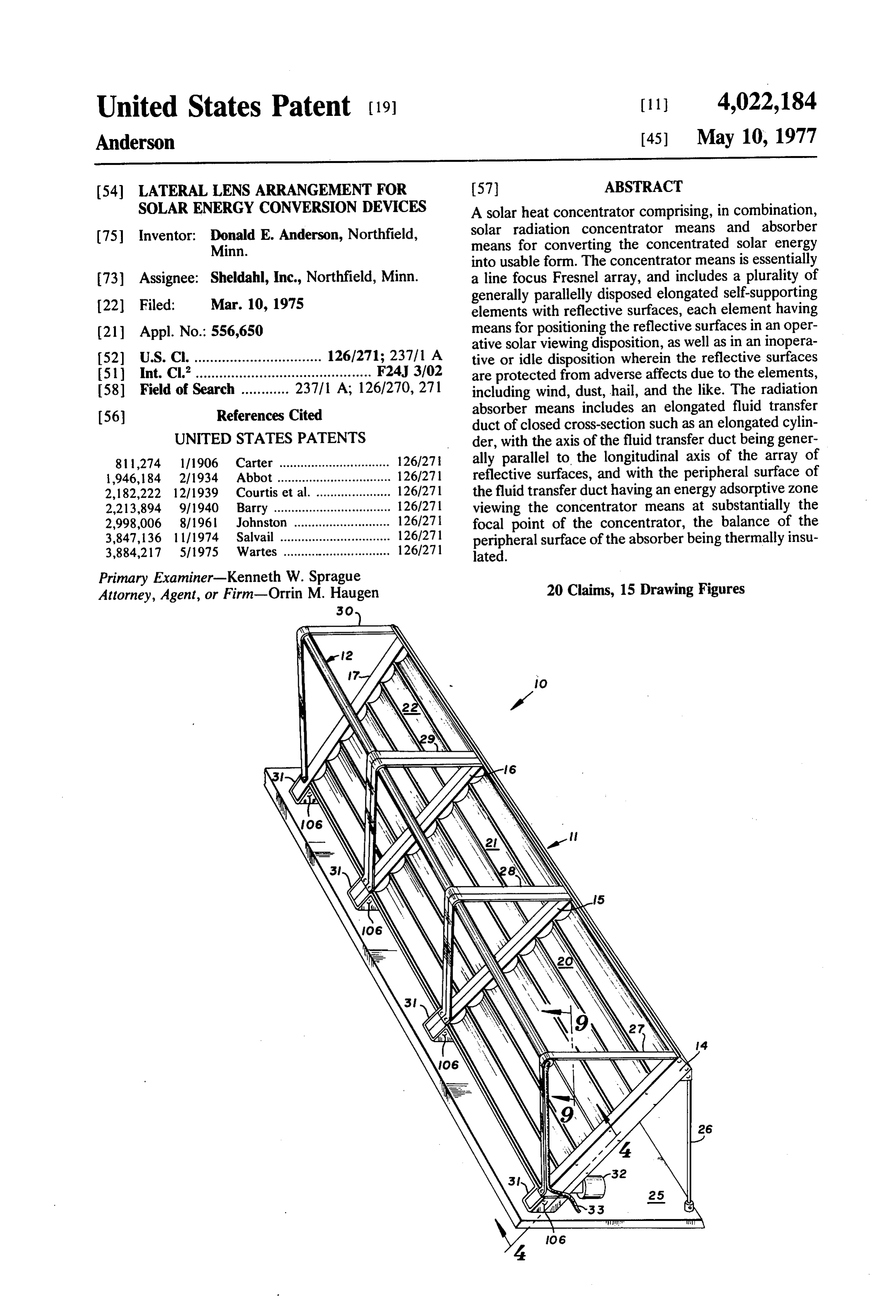
United States Patent (19) (11) 4,022,184 Anderson (45) May 10, 1977 (54) LATERAL LENS ARRANGEMENT FOR 57 ABSTRACT SOLAR ENERGY CONVERSION DEVICES A solar heat concentrator comprising, in combination, solar radiation concentrator means and absorber 75 Inventor: Donald E. Anderson, Northfield, means for converting the concentrated solar energy Minn.
into usable form. The concentrator means is essentially 73) Assignee: Sheldahl, Inc., Northfield, Minn. a line focus Fresnel array, and includes a plurality of generally parallelly disposed elongated self-supporting 22 Filed: Mar. 10, 1975 elements with reflective surfaces, each element having (21) Appl. No.: 556,650 means for positioning the reflective surfaces in an oper ative solar viewing disposition, as well as in an inopera 52) U.S. Cl. ................................ 126/271; 237/1 A tive or idle disposition wherein the reflective surfaces (51) int. Cl”............................................ F24, 3/02 are protected from adverse affects due to the elements, 58) Field of Search ............ 237/1 A; 126/270, 271 including wind, dust, hail, and the like. The radiation (56) References Cited absorber means includes an elongated fluid transfer duct of closed cross-section such as an elongated cylin
UNITED STATES PATENTS - der, with the axis of the fluid transfer duct being gener 81 1,274 l/1906 Carter ............................... 126/27 ally parallel to the longitudinal axis of the array of 1946, 184 2/1934 Abbot ................................ 126/271 reflective surfaces, and with the peripheral surface of 2,182,222 12/1939 Courtis et al. ..................... 126/271 the fluid transfer duct having an energy adsorptive zone 2,213,894 9/1940 Barry ................................. 126/271 viewing the concentrator means at substantially the 2,998,006 8/1961 Johnston 126/27 focal point of the concentrator, the balance of the 3,847,136 l l 1974 Salvail ............................... 126/271 peripheral surface of the absorber being thermally insu 3,884,217 5/1975 Wartes .............................. 126/271 lated.
Primary Examiner-Kenneth W. Sprague
Attorney, Agent, or Firm-Orrin M. Haugen 20 Claims, 15 Drawing Figures
Page 2
Drawing sheet — no readable text.
Page 3
Drawing sheet — no readable text.
Page 4
Drawing sheet — no readable text.
Page 5
Drawing sheet — no readable text.
Page 6
Drawing sheet — no readable text.
Page 7
Drawing sheet — no readable text.
Page 8
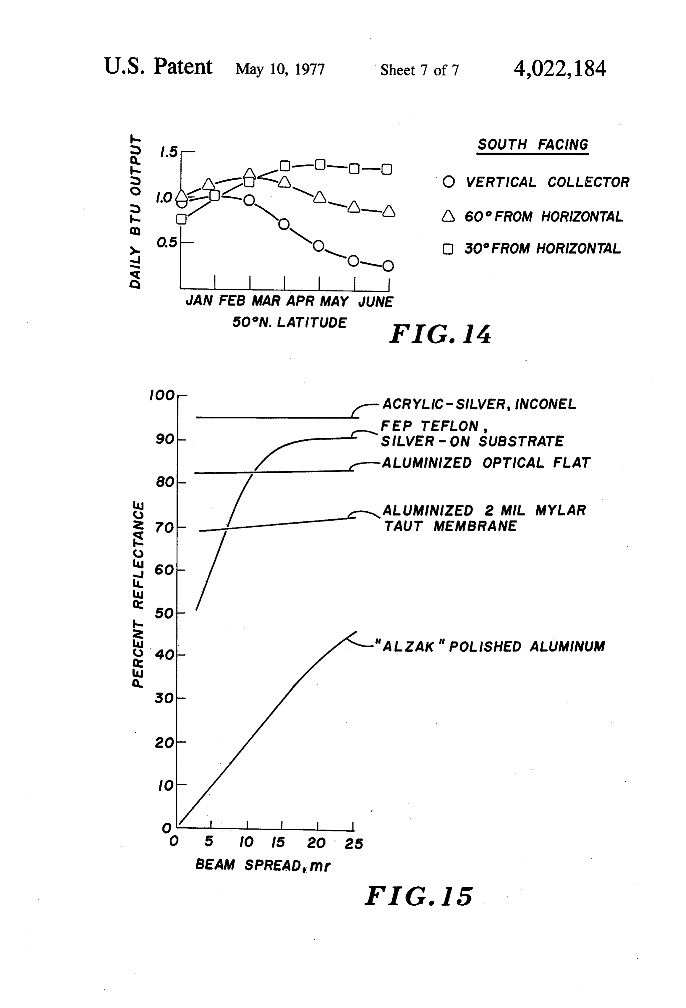
No O 3O FROM HORIZONTAL
JAN FEB MAR APR MAY JUNE
- ACRYLIC-SILVER, INCONEL
FEP TEFLON,
-ALUMINIZED OPTICAL FLAT
ALUMNIZED 2 MIL MYLAR
7O A - fair MEMBRANE
BEAM SPREAD, mr
FIG. I5
Page 9
cally disposed cylindrical parabolas may be employed
LATERAL LENS ARRANGEMENT FOR SOLAR to form the line array, with the collector or absorber ENERGY CONVERSION DEVICES means being arranged generally accordingly, and with
BACKGROUND OF THE INVENTION
the elongated axis of the cylindrical parabolas being, of 5 course, generally parallel to the elongated axis of the
The present invention relates generally to an im collector or absorber. r proved solar energy collector, and more particularly to It has been predicted that the total electrical powe a solar heat concentrator which includes, in combina demand for the United States of America in the year tion, a solar radiation concentrator means in the form 1980 will be approximately 9 x 10' Kilowatt-hours. of a line focus Fresnel array, and an absorber means O This power demand is substantially equivalent to that cooperating with the array for receiving the concen amount of incident solar radiation falling upon an area trated solar energy. With the continuing utilization and of only 1,531 square miles of land area located at ap ultimate partial depletion of available fossil fuels, alter proximately 33° North Latitude in a given year. Such a nate sources of energy have become desirable, pro latitude is substantially coincident with that of the State vided feasible means and techniques can be found for 15 of Arizona. Assuming an efficiency of conversion to their utilization. In this connection, solar energy may solar energy to electrical energy of only 15%, the area be employed as a high-grade power source for the gen required to obtain the projected electrical power de eration of usable energy with this source of energy mand for the United States of America in the year 1980 being freely available and non-polluting to the environ is approximately 10,000 square miles, with the area ment. Conversion of solar energy into usable energy 20 reasonably being expected to provide at least a substan may typically be achieved by thermodynamic arrange tial portion of the projected electrical power demand ments, such as, for example, by the generation of steam for the United States of America for the calendar year or other heated fluid for ultimate utilization at a power 1980.
conversion site. One approach which is commonly Solar energy is, of course, available for immediate taken for conversion of solar energy is the utilization of 25 conversion without further depletion or utilization of flat absorbers to heat a fluid transfer medium such as fossil fuels. The system of the present invention renders water, the heated water then being transferred to either it possible to fabricate relatively modest solar energy a thermally insulated reservoir or a zone wherein heat conversion plants suitable for use in heating and cool may be extracted. Such absorbers are normally re ing of residential dwellings, as well as commercial es ferred to as "flat plate collectors.” Since collector sur 30 tablishments with modest to moderate power require face area must be substantial, the cost of such collec ments. This system efficiently and economically con tors along with the thermal efficiency at low ambient verts solar energy to other usable forms of energy at an temperatures renders certain designs disadvantageous. amortized cost no greater than that cost required for These disadvantages are overcome with the structure fossil fuel conversion.
and design of the present invention. 35 At those latitudes in which the United States of In conventional or known solar energy systems, such America is situated, sunlight is never available on a as flat plate collectors or the like, a number of common 24-hour per day basis, and at the same time, each day problems have existed and the existence of these prob of the solar year provides a certain reasonable amount lems has retarded the growth and acceptance of solar of potential sunlight. The sun is, nevertheless, available heating systems. Normally, the primary problem is the 40 for exposure to the surface of the ground for a maxi initial on-site installation cost, with this cost normally mum of 50% of the total time of a given year within any being large due to the excessive size of conventional given location. Depending upon climatic conditions, systems. Furthermore, complex manifolding of the there will be a reduction from the 50% maximum occa individual collectors in the system has presented prob sioned by cloud cover, as well as a reduction due to the lems due to leakage effects and the like. The weight of 45 presence of natural or artificial obstacles. However, the installation has also presented problems, particu with the time available for exposure to the sun, it is, larly the weight of a fluid-loaded system. When a roof nevertheless, economically feasible to employ solar mounted flatplate system is specified, particularly in an energy as the primary source of energy, with this pri existing structure, the load bearing capability of the mary source being supplemented by available fossil structure is frequently insufficient to support the fluid 50 fuels. It will be appreciated that the utilization of fossil loaded systems and structural supports must be pro fuels may be required only during the night-time hours, vided. A further problem has existed with most flat or upon the occurrence of periods of heavy and ex plate solar heating elements, due to the low velocities tended cloud cover.
normally utilized in the system. With low velocities, SUMMARY OF THE INVENTION fluid corrosion and plugging of transmission lines may 55 be more likely to occur than in systems employing high The system of the present invention employs an array velocity transfer rates. of solar reflectors, grouped together so as to form a Conventional flat plate systems are normally cost-ef solar radiation concentrator means in the form of a line fective only if both heating and cooling may be focus Fresnel array, with each of the reflective ele achieved in a single installation, with a coefficient of 60 ments being focused upon a solar absorber means, the performance being necessarily greater than about 0.6 solar absorber preferably being in the form of one or in the cooling mode. With the existence of such a re more elongated cylindrical ducts. With this system, as quirement, gaseous fluid cooling is not generally feasi in certain others, it is possible to achieve solar power ble. dependency for a given installation in substantial ex In the present solar heat concentrator system, the 65 cess of the available sun time by means of utilization of design illustrated is one employing generally horizon energy storage, such as, for example, the use of heat tally disposed cylindrical parabolas forming the array. pumps, thermal storage vessels, reversible hydraulic It will be appreciated, of course, that generally verti pumping, reversible electrolysis or electrolytic cells, or
Page 10
electrolysis with storage of evolved oxygen and hydro rotated at a rate equal to these movements during the gen. In the electrolysis sytem, the evolved gases subse daytime hours. Preferably, the individual structures quently are combined for burning, thus replacing the carrying the reflective surfaces are ganged together so fossil fuels which may otherwise be required. At the as to move the surfaces as a unit. In other words, in present time, local weather forecasting techniques are order to compensate for differences in the angular sufficiently sophisticated so as to provide a reasonably reflection required to focus the reflective surfaces onto accurate prediction for at least a 24-hour period, hence the absorber means, the individual cylindrical parabo it is reasonably possible to anticipate demand require las will be adjusted to achieve the approximation of a ments and ultimate availability of solar energy to meet lateral Fresnel lens. Accordingly, the entire array of these demand requirements. O cylindrical parabolas may be rotated in time with the Briefly, in accordance with the present invention, a diurnal movements of the sun in order to maintain the solar heat concentrator is provided which includes a surface focal point for the incident solar radiation upon the line focus Fresnel array of solar reflective elements of the absorber means. which, in combination, provide a solar radiation con Also, in order to protect the reflective surfaces from centrator means, this radiation concentrator means 15 adverse weather conditions such as hail storms, dust functioning in combination with solar absorber means storms, and the like, means are provided for rotating for receiving the concentrated solar energy and con the individual reflective surfaces to an inoperative or verting the energy into a form which will render it idle disposition wherein the reflective surfaces are usable in a conventional fashion. The reflective ele pointed downwardly toward the ground or other sup ments comprise a plurality of generally parallelly dis 20 porting surface. In certain instances, it may be desir posed of elongated elements having a reflective surface able to provide for adjustably tilting the elevation angle thereon so as to form a line focus Fresnel reflective of the lateral end support columns for the arrays so as array, with means being provided for the purpose of to maximize the effectiveness of the reflective surfaces, compensating for diurnal changes in solar elevation, while minimizing shadowing effects.
thereby adjustably positioning the angular elevational 25 Adjustable control of the angular disposition of the disposition of each of the reflective surfaces into a individual reflective elements may be accomplished desired solar viewing disposition. The individual reflec with a single drive motor operating a gang of pre tive elements are ganged together so as to tiltably com arranged reflective elements. Similar techniques may pensate for solar elevation changes, with linkage means be utilized in order to control the angular disposition of being provided to effectively gang the surfaces to 30 the lateral support elements so as to achieve control of gether. Inasmuch as the array contemplates a line fo the "shadowing effect” of individual reflective ele cus, azimuth compensation is not normally required. ments, one upon another, however due to the slow rate Also, means are provided for rotatably positioning the of change of solar elevation between the seasons of the individual reflective elements forming the array in in year, this angular adjustment feature need not be auto verted inoperative or idle disposition so as to provide a 35 matically accomplished.
means of protecting the surface from continued expo The individual structures forming the reflective sur sure to the elements, such as adverse conditions due to faces are preferably cylindrical parabolas and are nor hail, blowing dust, and the like. mally designed to be held in end support columns. The absorber means includes an elongated fluid Therefore, it is preferable that the individual elements transfer duct, preferably cylindrical and having its cy 40 forming the reflective assemblies or cylindrical parabo lindrical axis extending generally parallel to the elon las be free standing, non-deforming, and accordingly gated axis of the reflective surfaces. The cylindrical optically stable. Inasmuch as the individual elements fluid transfer duct has a closed peripheral surface, with are ganged together, and inasmuch as the elements may the outer periphery having an energy absorptive por be rotated from only one of the two spaced end sup tion or zone arranged in viewing relationship to the 45 ports, the cylindrical parabolas will be functioning as reflective surfaces, with this portion of the outer pe torque-tubes and therefore they should be sufficiently riphery of the fluid transfer duct being disposed at or rigid so as to withstand the forces to which they are along the focal point of the line focus Fresnel array. subjected. The mechanical requirements for the collec That portion of the periphery of the fluid transfer duct tor are, of course, consistent with those of the reflec which is not in viewing relationship to the reflective 50 tors. The collector must be sufficiently rigid so as to be elements, or is otherwise remote from the focal point, is non-deforming between supports, and must be capable normally covered with a thermal barrier for substan of compliance while withstanding the design tempera tially reducing thermal energy losses from the fluid tures to which it is being exposed.
transfer duct. Preferably, the radiation absorber means Because of the design characteristics of the system, it is disposed at a location between the sun and the reflec 55 is possible to retro-fit the system to existing structures tive surfaces, and at an elevation which is vertically as well as to apply the system as the primary thermal above the plane of the reflective elements. In order to system in new construction. The capability of protect concentrate the incident solar radiation, the elongated ing the individual reflective elements during extreme reflective elements which form the reflective surfaces weather conditions also provides a safeguard against are preferably formed as arcuate segments defining 60 burn-out of the collector under no-load conditions. In cylindrical parabolas, although it will be appreciated other words, under a situation wherein there is no call that flat reflective surfaces may be employed in certain for additional energy, the individual reflector elements installations as well. The focal length of each of the forming the line focus Fresnel array are de-focused, parabolas will therefore be substantially equal to the such as by turning the reflective surface toward the distance from the reflective surface to the surface of 65 ground.
the absorber means. In order to accommodate the diur By way of location relative to the demand area, it will nal arcuate elevational movements of the sun, the indi be appreciated that the system collector can be used in vidual cylindrical reflective parabolas will be arcuately any location with good sun exposure. Examples of such
Page 11
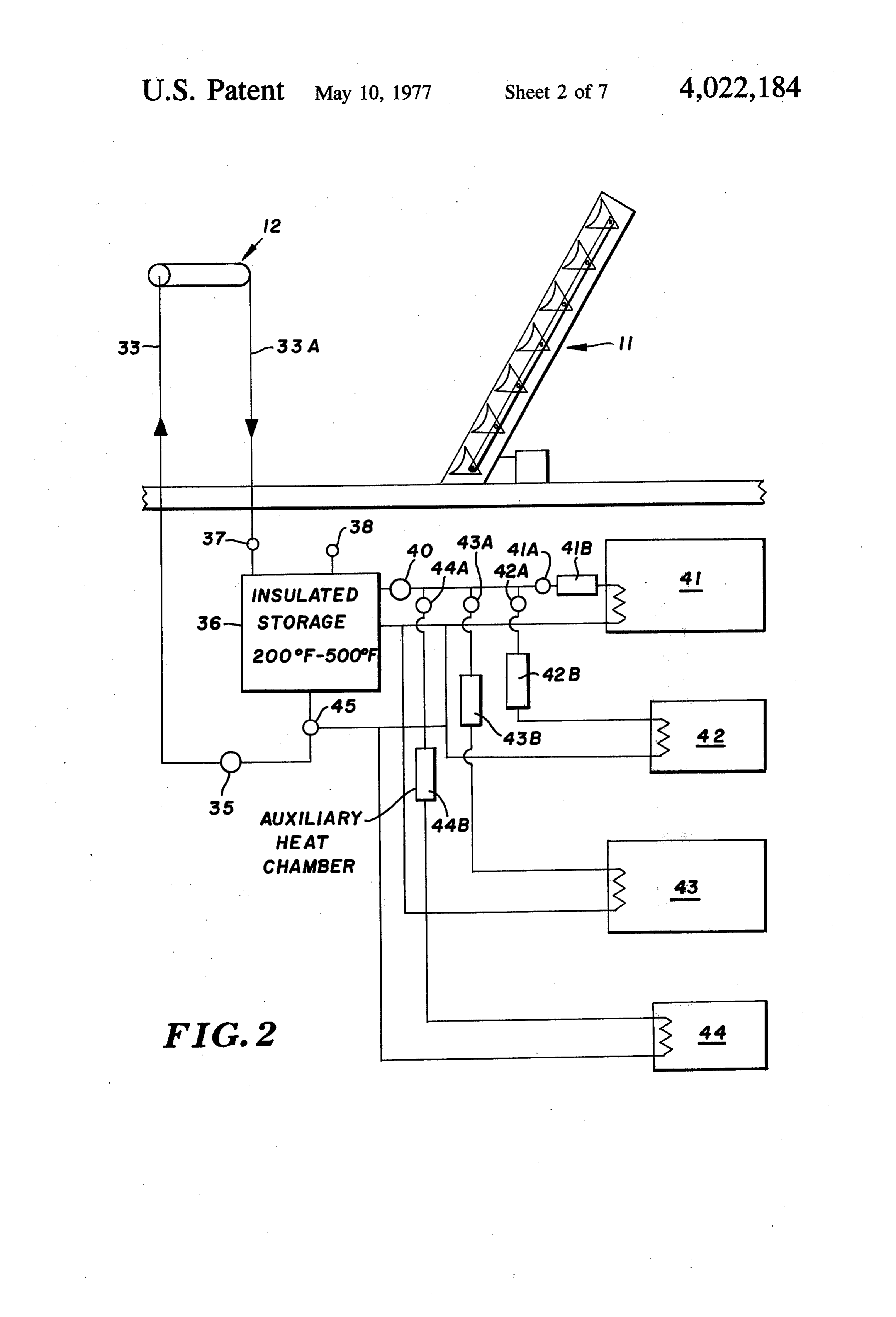
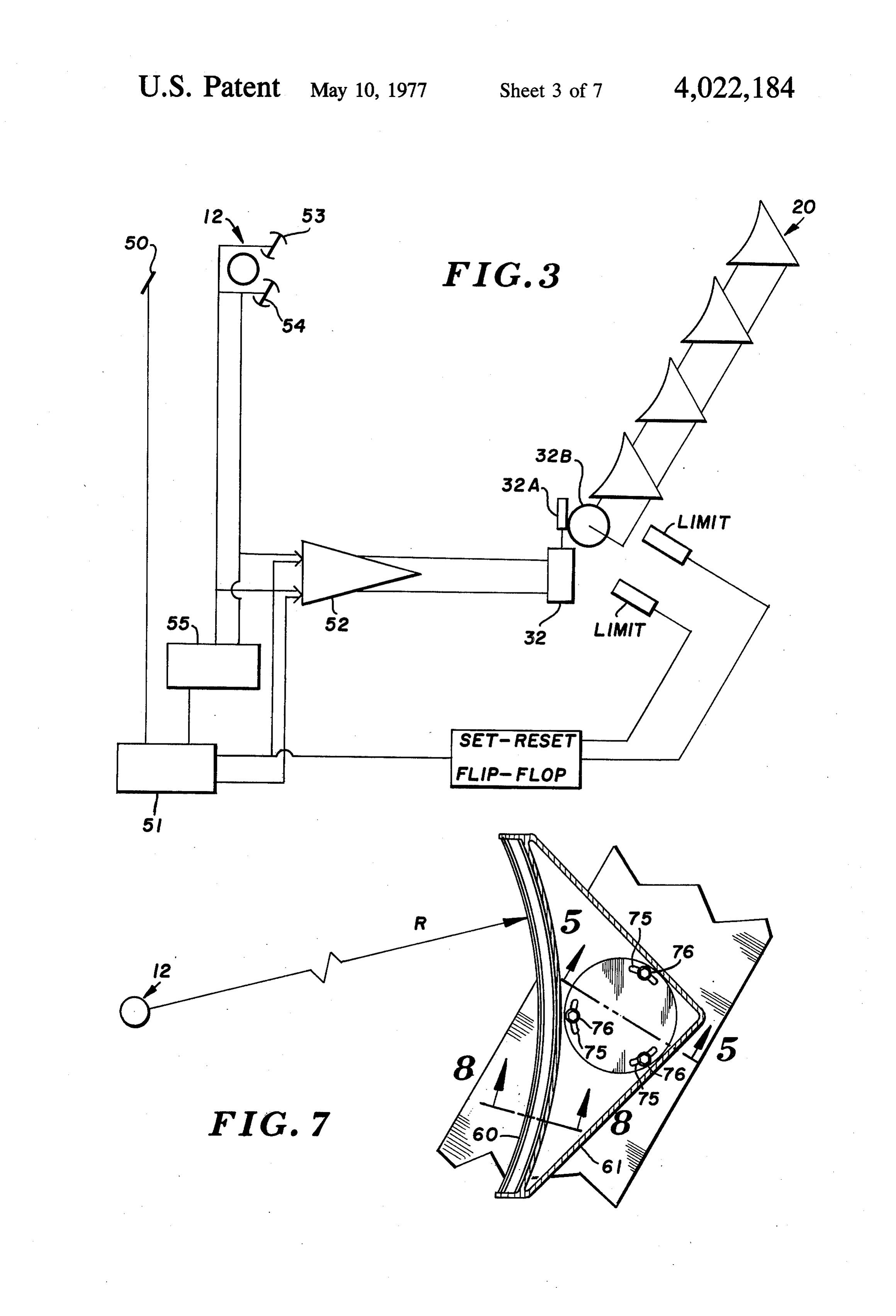
locations include parking lots, fence lines, roofs of FIG. 2 is a schematic diagram of a typical system commercial and residential structures, and South-fac installation utilizing the features of the present inven ing walls. tion;
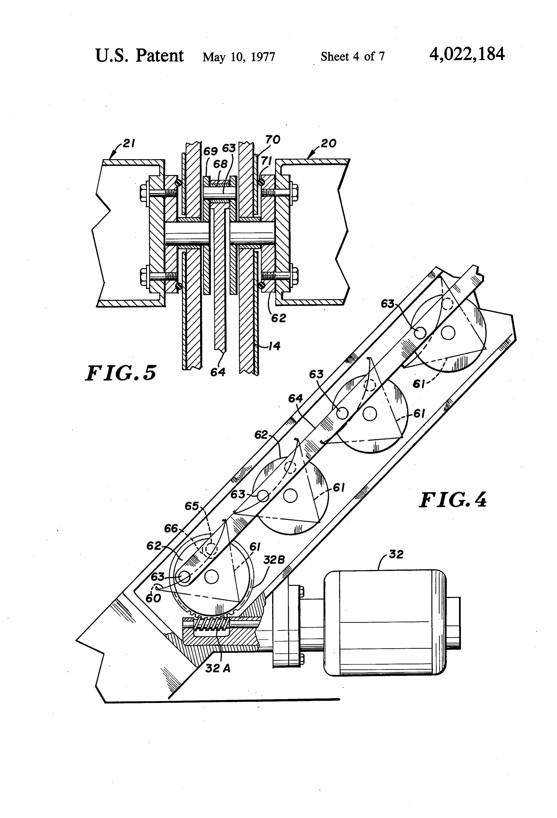
Therefore, it is a primary object of the present inven FIG. 3 is a schematic diagram of a drive and tracking tion to provide an improved solar heat concentrator 5 system that may be employed in combination with the which comprises in combination, a solar radiation con system of the present invention; centrator means and absorber means for receiving the andFIG. 4 is a side elevational view, partially in section, illustrating the details of a typical drive system for concentrated solar energy from the concentrator, the the line focus Fresnel array of the present invention; concentrator means comprising a plurality of generally parallelly disposed reflective elements forming a line 10 FIG. 5 is a detail sectional view of the drive means focus Fresnel array focused upon a surface absorber illustrated in FIG.4, and taken along the line and in the direction of the arrows 5-5 of FIG. 7;
eaS.
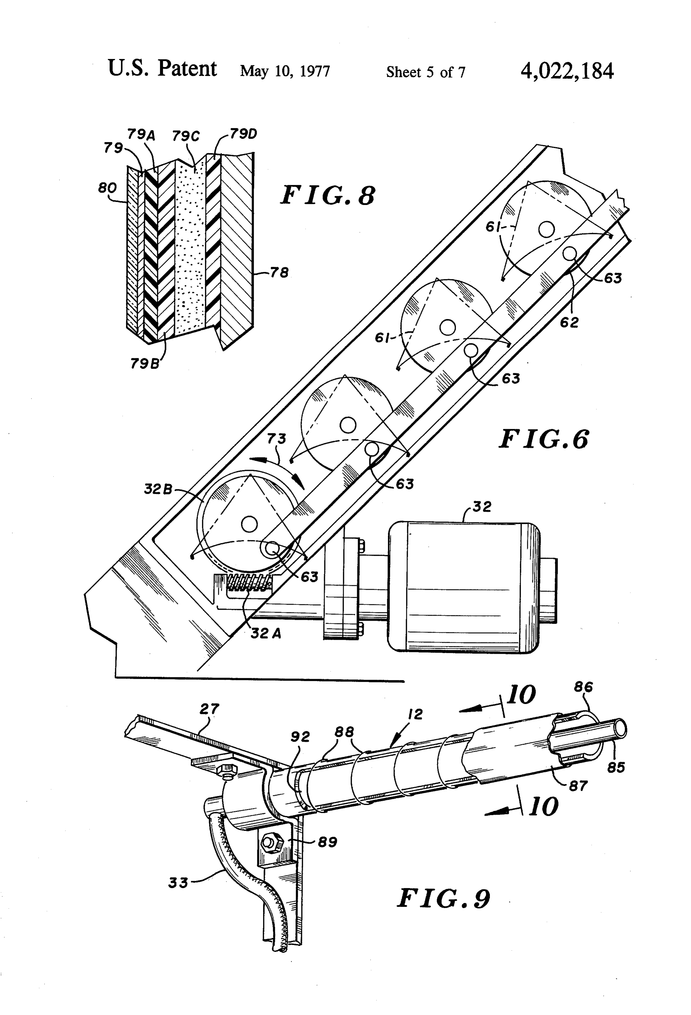
It is a further object of the present invention to pro FIG. 6 is a view similar to FIG. 4, and illustrating the vide an improved solar heat concentrator which com 15 disposition elements of of the drive mechanism with the individual the line focus Fresnel array being inverted prises in combination, a solar radiation concentrator so as to respond to a no-load situation or become pro means in the form of a line focus Fresnel array and an tected from adverse environmental conditions; absorber means for receiving the concentrated solar FIG. 7 is a detail side elevational view of a typical energy, the absorber means including an elongated reflective panel in the array, and being in the form of a fluid transfer duct preferably having a cylindrical axis 20 cylindrical parabola, and illustrating the disposition of and extending generally parallel to the elongated axis the panel relative to the absorber means, this figure of the reflective array, and with the peripheral surface being shown infragmentary form;
of the absorber means including a thermal energy ab FIG. 8 is a detail sectional view on a slightly enlarged sorptive zone and a thermal insulative zone, with the scale, and taken along the line and in the direction of absorptive zone being in viewing relationship to the 25 the arrows 8-8 of FIG. 7;
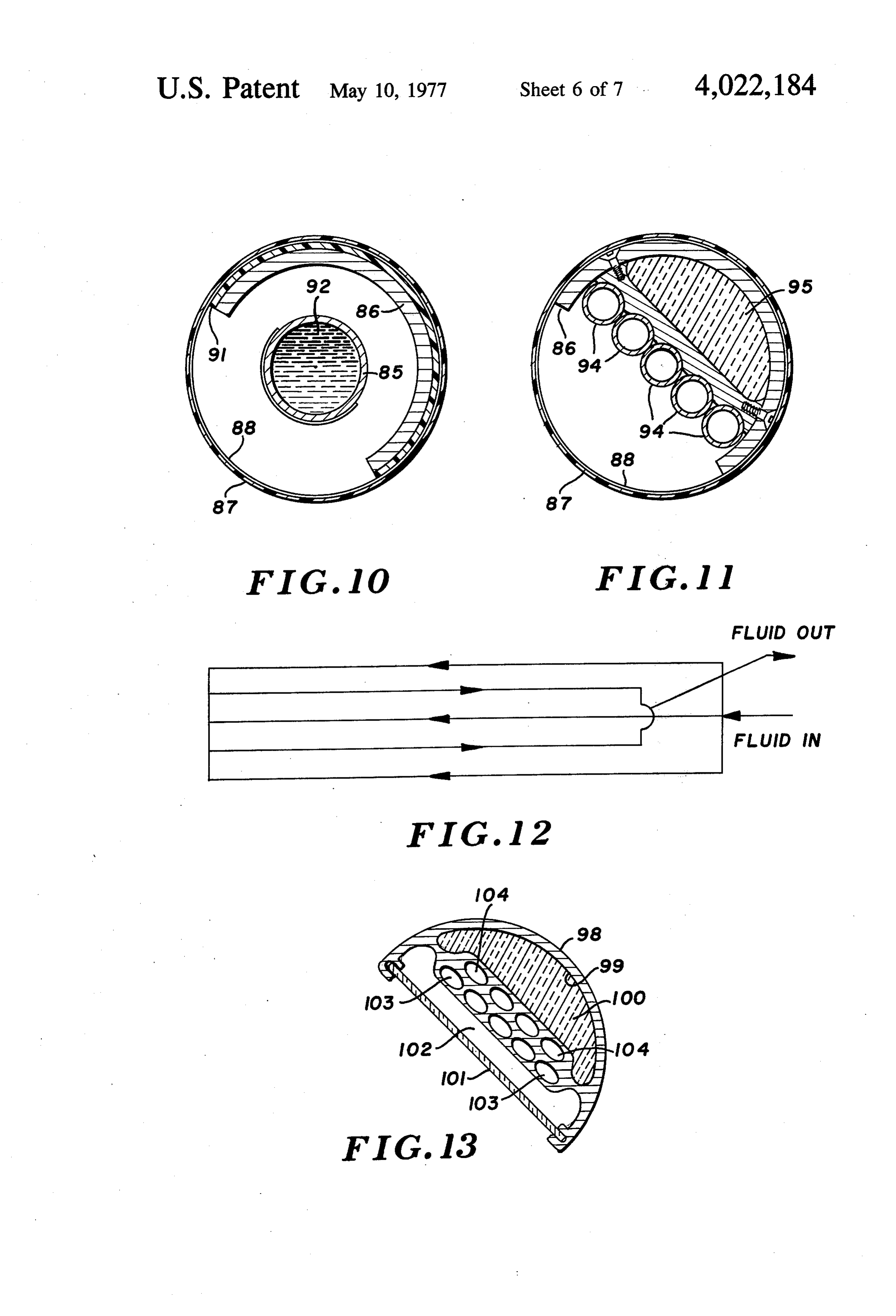
reflective surfaces of the reflective array, and disposed FIG. 9 is a fragmentary view of a portion of the ab generally within the focal line thereof. sorber means illustrated in FIG. 1, with this view being It is yet a further object of the present invention to taken provide an improved solar heat concentrator means 9-9 ofalong the line and in the direction of the arrows
which employs a solar radiation concentrator means 30 FIG. 10 is a vertical sectional view of the absorber and an absorber means for receiving concentrated solar means illustrated in FIG. 9, and is taken along the line energy, the solar radiation concentrator means com prising a plurality of generally parallelly disposed cylin andFIG.in the direction of the arrows 10-10 of FIG. 10; 11 is a view similar to FIG. 9, and illustrating a drical parabolas forming a line focus Fresnel array, modified form of absorber means utilizing a plurality of each having a reflective surface with the focal line of 35 axially parallelly disposed fluid transfer ducts; each of the reflective surfaces being generally coinci-- FIG. 12 is a typical flow diagram which may be em dent with the surface of the absorber means, and with ployed in the arrangement illustrated in FIG. 10; means being provided to simultaneously control the FIG. 13 is a view similar to FIGS. 10 and 11, and disposition of each reflective surface in the array so as illustrating still another modified form of absorber to maintain the reflective surface in solar viewing dis 40 means which may be employed in combination with the position. present invention;
It is yet a further object of the present invention to FIG. 14 is a graph illustrating a family of curves plot provide an improved solar heat concentrator which ting daily output in BTU's vs. months of the calendar comprises a solar radiation concentrator means and year at 40' North Latitude, with each member of the absorber means for receiving the concentrated solar 45 family of curves illustrating a different degree of incli energy, and wherein a plurality of generally parallelly nation from the horizontal for the lateral supports of disposed cylindrical parabolas are provided forming a the line focus Fresnel array of deflectors, of the type line focus Fresnel array, each having a reflective sur illustrated in FIG. 1; and face with a focal line generally concident with the sur FIG. 15 plots a measure of specularity of various face of the absorber means, and with drive means being 50 laminate materials useful in the fabrication of the re provided to gang position each of the reflective sur flective panels employed in the present invention, plot faces in solar viewing-collector reflecting disposition, ting percent reflectance vs. milli-radians of beam and further being provided with means to rotate the spread in the relevant range of requirements for the solar reflective surface into a non-solar viewing dispo line focus Fresnel collector array. sition either under no-load conditions, or to shield or 55 DESCRIPTION OF THE PREFERRED otherwise protect the reflective surface in the event of EMBODIMENT adverse weather conditions such as falling hail, blowing dust, or the like. In accordance with the preferred embodiment of the Other and further objects of the present invention present invention, and with particular attention being will become apparent to those skilled in the art upon a 60 directed to FIG. 1 of the drawings, the solar heat col study of the following specification, appended claims, lector system generally designated 10 comprises, in and accompanying drawings. combination, a solar radiation concentrator means in the form of a line focus Fresnel array generally desig
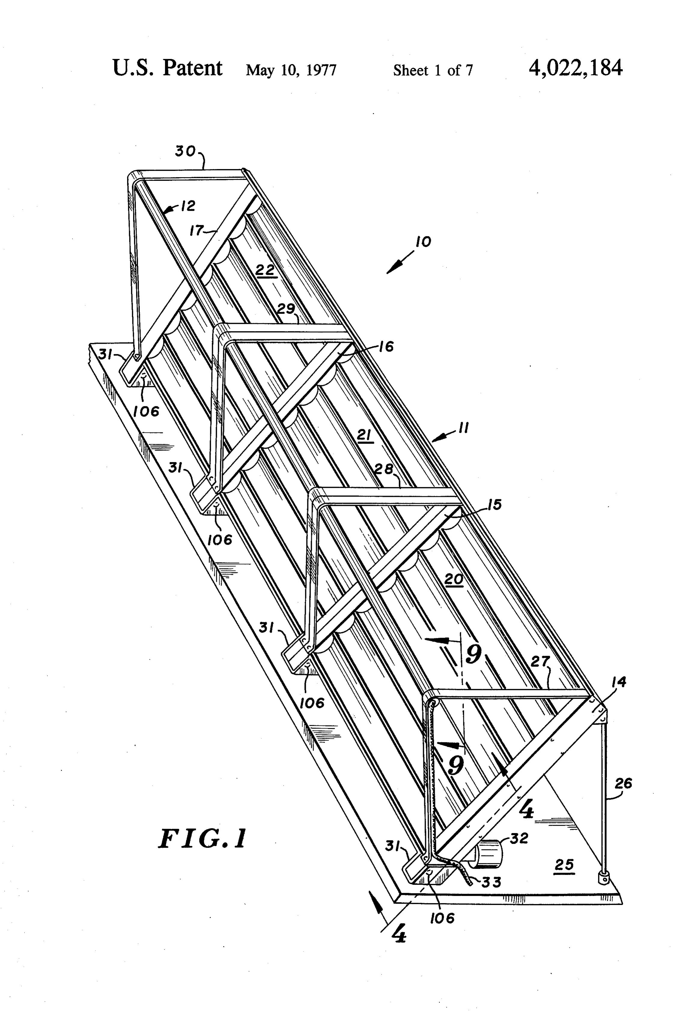
BRIEF DESCRIPTION OF THE DRAWINGS nated 11, together with an absorber means generally FIG. 1 is a perspective view of a typical installation 65 designated 12. In the concentrator means, a plurality of utilizing the line focus Fresnel array of reflective ele lateral support columns are provided for the array 11 as ments in combination with a fluid transfer absorber at 14, 15, 16 and 17 with the support columns being means; provided to establish spaced supports for the free
Page 12
standing non-deforming slat elements such as the ele Upon sufficient light striking sun sensor 50, the No. 1 level discriminator 51 which is, in turn, coupled at its ments included in the array 11. As is apparent from output
FIG. 1, three individual arrays are being employed, to differential amplifier 52 drives the differen these arrays being identified at 20, 21 and 22. Each of tial amplifier 52 and, in turn, drive motor 32. The indi vidual reflective panels as have been described at 20 in the individual slats or cylindrical parabolas incorpo 5 FIG. 1 rotate from the "storage' or protective mode as rated in the system is identical, one to the other, and illustrated hence the description of one such element will suffice in FIG. 3. inIn FIG.
order 6 to the active mode as is illustrated to protect the immediate environ for a description of all.
Support means are provided for the solar heat con ment,member the drive motor 32 may, through its worm gear centrator means such as a base pad 25 having support 10 drive 32A and ring gear 32B drive the individ ual reflector elements 20 in a counter-clockwise direc posts along each of the columns 14, 15, 16 and 17 as at tion until focus is achieved on the collector 12. There 26. A bracket means is provided for supporting the fore, the focused beam will strike optimizing sensors 53 absorber 12 along each column as well, such as is illus and 54 at which time the No. 2 level discriminator as trated at 27, 28, 29 and 30. Suitable mounting pads are 15 shown at 55 overrides the output of sun sensor 50 and provided for the individual columns 14-17 inclusive, causes a signal to differential amplifier 52 which, in such as at 31-31. As will be made more apparent here turn, is utilized to drive motor 32 and position the sun's inafter, a drive motor is provided for the arrays 20, 21 image directly on the collector pipe 12. Preferably, the and 22 such as is illustrated at 32, with one motor sun sensors 53 and 54 will be disposed in a zone such driving one or more arrays. Transfer fluid is provided that direct incident reflected light does not impinge for the absorber through a liquid feed line 33, with an directly on the surface of the sensor. This is due to the outlet or discharge line (not shown) being provided at high intensities involved. Therefore, these optimizing the opposed end of absorber 12, or, alternatively, coin sensors cidentally with liquid line 33 either being coaxially housing 53 and 54 will normally be disposed within a seeing reflected light only.
arranged or parallelly disposed. 25
As has been indicated, the individual reflectors are B. Intermittent Sun Failure ganged together so as to achieve a line focus on the A built-in time delay allows the No. 2 level discrimi absorber means. With attention now being directed to nator 55 to hold the panel members 20 in position. FIG. 2 of the drawings, an example of a system sche When the time delay, typically in the range of approxi matic is illustrated wherein a line focus Fresnel array of 30 mately 5 minutes is exceeded before reappearance of reflectors in the system 11 is focused upon the absorber the sun, effective control will revert to the No. 1 level means 12, with an inlet line being illustrated at 33 and discriminator 51 and the sensor input control reverts an outlet or discharge line being illustrated at 33A..The from the optimizing sensors 53 and 54 to the sun sensor heated fluid passing through absorber 12 is forced by 50.
means of pump 35, with insulated storage vessel 36 35 being employed to retain the heated fluid for distribu C. Total Sun Failure tion through other zones, as required. Storage vessel 36 In the event of total sun failure, the sun sensor 50 is is adapted to retain fluid at an elevated temperature, delivering no signal to No. 1 level discriminator 51, and such as from 200 F. to about 500 F. Temperature this condition will be utilized to deliver a signal to dif gauges 37 and 38 monitor the condition of the fluid 40 ferential amplifier 52 which will return the reflectors entering the vessel 36 as well as the material within 20 to the "storage' disposition or mode as is illustrated vessel 36. Pump 40 is used to carry fluid from vessel 36 in FIG. 6. As is indicated in FIG. 6, the reflective sur to any of the working stations or zones such as the heat face is directed downwardly, toward the surface of the exchanger for building heat as at 41, a hot water tank as ground, thereby enhancing the ability of the system to at 42, a heat exchanger for absorbing air conditioning 45 protect the face surfaces of the reflectors from environ as at 43, as well as a zone for process heating as at 44. mental damage.
Alternatively, a mechanically coupled compressor may be utilized to provide air conditioning and potential D. High Limit Control heat pumping with mechanical energy being delivered The system illustrated in FIG. 3 is adapted to utiliza by a Rankine Cycle Prime Mover powered by the 50 tion of a high limit control which may be a temperature stored solar heat. In the illustrated system, individual gauge such as temperature gauge 37 illustrated in the valves such as 41A, 42A, 43A and 44A control the flow discharge line 33 of collector pipe 12 in FIG. 2, this of fluid from pump 40 to each of the individual zones, device acting as a condition sensing element to provide as illustrated, with three-way valve 45 being employed high limit control under modest or no-load conditions. to direct the return flow either to storage vessel 36 or to 55 This sensor may be utilized to provide a signal to differ pump 35. Thus, it will be seen that the system has appli ential amplifier 52 which will override the sun sensor cation to a variety of processes, and is essentially with 50 and return the system to storage mode. This ar out limitation in this regard. Also, as has been indi rangement will prevent continued operation and over cated, it is possible to employ auxiliary heat as at 41B, heating of the fluid contained in the system. 42B, 43B and 44B for the individual lines from vessel 60 GENERAL OPERATION 36 in order to deliver fluid at a constant elevated tem perature. Attention is now directed to FIGS. 4 and 5 of the Attention is now directed to FIG. 3 of the drawings drawings wherein details of the linkage means being wherein a drive and tracking system for the solar heat utilized to move the individual reflector panels in the concentrator arrangement of the present invention is 65 array is shown. The reversible drive motor, as previ illustrated. ously discussed, is illustrated at 32 and is provided with its worm 32A which, in turn, is in mesh with ring gear
A. Totally Unobstructed Sunlight 32B on the base member of the array, such as reflective
Page 13
face per se. In this design, surface 60. Each of the individual reflector panels is tion of articulating mechanisms therefore, optimum utiliza stretched tautly across triangular frame arrangement may be achieved. Attention is now directed to 61, as illustrated in both FIGS. 4 and 7, with the triang wherein a section of a typical reflector FIG. 8 of the drawings ular frame 61 being sufficiently durable and rigid so as trated. As will be appreciated, the structure surface is illus to provide a torque-tube for the rotation of the individ the reflective surface is one of constant cross-section supporting ual members of the linear focus array, with the torque as to function as a torque-tube. This structure provides so tube functioning in non-deforming fashion. Deforma a mounting base for the reflective surface, as well as a tion would, of course, present problems in the ultimate focusing of the individual members on the collector protective reflective backing therefor. Inasmuch as the individual elements are supported at their spaced apart
In order to couple the individual reflectors together ends, the structures must be sufficiently rigid so as to in gang relationship, crank pins are provided on the avoid deflection upon those lateral loads occurring due circular end plates 62-62 of each of the panels, with toInwind loading and torque loading during adjustment. the embodiment illustrated in FIG. 8, a metal the end plates carrying eccentric pins 63-63. Linkage 15 backing plate or channel member is illustrated at 78, arm 64 is, in turn, coupled across each of the individual upon which is applied a metallizing layer of high reflec pins 63 so as to achieve ganged motion of each of the tance such as at 79. A transparent plastic protective individual reflectors in the array. coating is provided as at 80 so as to cover the metal As is illustrated in FIG. 4, the opposed end column is lized layer 79. In order to achieve optimum reflectivity, likewise provided with a similar pin and arm arrange 20 metallized layer 79 is preferably either aluminum, or, in ment, with one such eccentric pin being illustrated in phantom at 65. A second arm is also provided as illus some instances, silver. A film of metallizing in excess of trated in phantom at 66, with the pins and arms 65 and approximately sufficient 2000A is normally required to achieve density of the metallized layers to achieve 66 being offset in arcuate distance of 90° from those enhanced reflectivity. For those metals, silver and alu illustrated in solid lines at 63 and 64 in FIG. 4. The reason for the offsetting is to avoid a condition of dead 25 minum, a film thickness of approximately 2000 A is normally sufficient, although when silver is being uti centering in the arrangement, thus insuring a positive lized, a thickness of approximately 1200A is perhaps and full drive during periods of motion.
FIG. 5 illustrates the individual elements in greater optimumomy.
from the standpoint of reflectance and econ detail. Connecting arm 64 is illustrated as being cou 30 In preparing a typical reflector member, a mold sur pled to eccentric 63 through bushing 68 and end plate face is provided having a convex surface for receiving or crank 69. The supporting column such as column 14 the sandwich of components making up the reflective is also illustrated in FIG. 5, with a covering plate 70 being preferably employed to eliminate dust and dirt surface. The initial layer to be applied to the surface from the confines of the arrangement. A dust and 35 will be a film of stress-oriented polyethylene tere phthalate. (Mylar) having a thickness of 2 mil, and weather seal in the form of an O-ring is shown at 71, being coated with aluminum, the aluminum having a wherein sealing engagement is made against the surface thickness of at least about 2000 A. A layer of fiberglass of cover member 70 and end plate 62 of the reflector is then applied to the stress-oriented polyethylene tere panel such as is illustrated generally at 20. It will be phthalate surface, and bonded thereto. Thereafter, a noted that the panel 20 illustrated in FIG.5 may be any 40 foam backing having of the individual panels in the array, with the exception inch, is applied to theafiberglass thickness of approximately 1 layer, in order to in of the bottom panel carrying the ring gear 32B. crease the modulus of the overall structure. The foam Attention is now directed to FIG. 6 of the drawings material is a structural foam such as polystyrene or wherein the storage or sheltered mode is illustrated. In polyurethane having a density of approximately 2 this disposition, the individual portions of the assembly 45 pounds per cubic foot. The back surface of the foam illustrated in FIG. 5 have been actuated so as to return member is thereafter to the storage disposition. As has been previously indi impregnated with a resin covered with a layer of fiberglass cated, the drive means is provided so as to de-focus the like. Each of the two layerssuch as epoxy resin or the line arrangement by rotating the individual elements in impregnated with a durable resin such isaspreferably of fiberglass epoxy or a clockwise direction from the disposition of FIG. 4 to 50 acrylic, with such resins being, of course, commercially that disposition illustrated in FIG. 6. Double-headed avilable. A protective coating is applied to the metal arrow 73 is shown for the purpose of illustrating the lized layer, with the protective coating preferably being operational movement between the dispositions of the an elements of the components in FIG. 4 from that of FIG. filmacrylic may be top coat in the form of a lacquer. A polymer successfully utilized for this purpose, how 6. ever. The transparent plastic coating 80 which func In order to provide for line focus of the array, on the 55 basis of a Fresnel array, individual arcuate adjustment tions as a protective coating for the metal is preferably slots are shown at 75-75 together with mounting acrylic or, although in certain instances, FEP Teflon screws 76-76 which are employed to provide an initial may be utilized. A film, if utilized, may be between about 0.25 mill up to about 1 mil with either being adjustment of the surface of the reflector panel onto appropriate. Typically, an outer film or protective coat collector pipe 12, as is illustrated. The focal length of 60 ing 80 is utilized, panel 60 is, in this instance, equal to the distance R as encloses aluminumsuch layer as an acrylic coating, which 79 which is prepared as an is illustrated in FIG. 7. In actual installation operations, aluminized coating of stress-oriented polyethylene therefore, the installer will position each of the individ terephthalate, such as at 79A. Such aluminized film in ual reflector panels in the array so as to achieve a com 65 the form of aluminized Mylar is available from the E. I. mon focal line for each. In this fashion, the incident DuPont deNemours Corp. of Wilmington, Del. A layer solar energy is concentrated from the panel onto the of epoxy fiberglass, cured to a rigid layer is shown at surface of the absorber means 12. Preferably, the pivot 79B with the urethane foam layer being shown at 79C. axis of the reflective surface is in the plane of the sur
Page 14
Drawing sheet — no readable text.
Page 15
surface. Thus, for example, a pattern of individual re each having focal lines converging upon said energy flective elements may be selected, with the focal length absorptive zone. - 8. The solar heat concentrator as defined in claim 1 of each being substantially that of the absolute distance between the surface of the reflective element and the wherein said energy absorptive zone is coated with a surface of the absorber. It will be further appreciated, 5 black 9.
film.
The solar heat concentrator as defined in claim 1 of course, that with a focal length of approximately 20 wherein said energy absorptive zone is covered with a feet, for example, a modest de-focusing will not signifi transparent film forming an enclosure about the sur cantly alter the effectiveness of the system inasmuch as face of said absorptive zone. the effective width of the absorbing surface may be 10. The solar heat concentrator as defined in claim 9 large when compared to the line focus contemplated. 10 wherein said transparent film is fluorinated ethylene claim:
1. In a solar heat concentrator comprising, in combi propylene.
nation, solar radiation concentrator means and radia wherein 11. The solar heat concentrator as defined in claim 1 tion absorber means for receiving concentrated solar per. said fluid transfer duct is fabricated from cop energy from said concentrator means; 12. The solar heat concentrator as defined in claim 1 a said solar concentrator means comprising a plural 15 wherein said radiation absorber means comprises a ity of generally parallelly disposed elongated re plurality of generally parallelly disposed fluid transfer flector elements each element having a reflective ducts.
surface and including means for controllably posi 13. The solar heat concentrator as defined in claim 1 tioning each of said reflective surfaces in solar 20 wherein said radiation absorber means is disposed be viewing and absorber reflecting disposition for tween the sun and said reflective surfaces.
accommodation of diurnal solar motion; 14. The solar heat concentrator as defined in claim 1 b. said radiation absorber means including an elon wherein coupling linkage means are provided between gated generally cylindrical fluid transfer duct hav adjacent reflective surfaces.
ing a cylindrical axis extending generally parallel to 15. The solar heat concentrator as defined in claim 1 the elongated axis of each of said reflective sur 25 including solar detector means for detecting incident faces, and with a generally closed peripheral sur solar radiation.
face, said peripheral surface being disposed about 16. The solar heat concentrator as defined in claim said cylindrical axis and having an arcuate portion 15 wherein condition responsive means are provided defining an energy absorptive zone and an arcuate for drivably rotating said reflective surfaces to gener portion defining a thermally insulative zone, with 30 ally vertically downwardly disposed disposition upon said energy absorptive zone being disposed in gen detection of absence of incident solar radiation. erally opposed relationship to said reflective sur 17. The solar heat concentrator as defined in claim 1 face, and with the balance of the arcuate surface of wherein solar radiation responsive means are provided said absorber comprising said insulative Zone and for controllably adjusting the arcuate disposition of being provided with a thermally insulative covering 35 each of said reflective surfaces in response to diurnal for substantially reducing the thermal energy losses changes in solar elevation.
18. The solar heat concentrator as defined in claim
therefrom, said fluid transfer duct being disposed 17 wherein said solar radiation resposive means are along a plane generally at least as high as that of the positioned uppermost of said elongated reflector elements. in oppositely disposed relationship of the 2. The solar heat concentrator as defined in claim 1 40 axis of said radiation absorber means. being particularly characterized in that said means for 19. In a solar heat concentrator comprising, in com controllably positioning said reflector elements in bination, solar radiation concentrator means and radia cludes means for rotation of each of said elongated tion absorber means for receiving concentrated solar surfaces about an axis disposed generally parallel to the energy from said concentrator means; a said solar concentrator means comprising a plural elongated axis of said reflective surface. 45 ity of generally parallelly disposed elongated re 3. The solar heat concentrator as defined in claim 2 being particularly characterized in that said means for flector elements each element having a reflective controllably positioning said reflective surfaces in surface and including means for controllably posi cludes means for directing said reflective surfaces verti tioning each of said reflective surfaces in solar cally downwardly. viewing and absorber reflecting disposition for 4. The solar heat concentrator as defined in claim 2 50 accommodation of diurnal solar motion;
being particularly characterized in that said means for b. said radiation absorber means including an elon gated generally cylindrical fluid transfer duct hav controllably positioning said reflective surfaces in ing a cylindrical axis extending generally parallel to cludes means for rotating said reflective surfaces about the elongated axis of each of said reflective sur an arcuate path upwardly and away from solar viewing 55 faces, the peripheral surface of said duct having an disposition. - arcuate portion defining an energy absorptive zone 5. The solar heat concentrator as defined in claim and an arcuate portion defining a thermally insula being particularly characterized in that said solar con tive zone, with said energy absorptive zone being centrator means comprises frame means for said elon disposed in generally opposed relationship to said gated reflective surfaces, and wherein laterally dis 60 reflective surface;
posed support columns are provided for mounting of c. said reflector elements including rigid frame means said frame means thereon. for providing self-supporting mounting of said re 6. The solar heat concentrator as defined in claim 5 flective surfaces at opposed ends thereof free of wherein means are provided for controllably tilting said torsional and flexural deflection. lateral support columns to accommodate seasonal vari 65 20. The solar heat concentrator means as defined in ations in solar elevation. claim 19 being particularly characterized in that said 7. The solar heat concentrator as defined in claim 1 rigid frame means includes an elongated support hav being particularly characterized in that said elongated ing a closed cross-section. ck k - k is reflective surfaces are line focus cylindrical parabolas,
Page 16
UNITED STATES PATENT OFFICE
CERTIFICATE OF CORRECTION
INVENTOR(S) . Donald E. Anderson
It is Certified that error appears in the above-identified patent and that said Letters Patent are hereby Corrected as shown below. Column 2, line l5, "to" should read -- of --. Column 3, line 21, "of" should be deleted. Column 5, line 47, "cylindrical" should read -- cylindrical --.
"deflectors" should read -- reflectors -- .
Column ll, line 25, "Pipe 85" should read
eigned and eealed this twenty-sixth Day of July 1977
SEAL
Attest.
Attesting Officer Commissioner of Patents and Trademarks

Provenance
- Collection
- Cited prior art
- Original PDF
- patentimages.storage.googleapis.com →
- Filed
- 1975-03-10
- Pages
- 16
- Method
- pdftotext (the PDF's own text layer) + pdftoppm 300dpi page scans
- Source
- Google Patents bibliographic record
- Granted
- 1977-05-10
- Inventors
- Donald E. Anderson; Sheldahl Inc
- Transcribed from
- patentimages.storage.googleapis.com →