patent · US1672750
Solar heater
5 June 1928
Page 1
Drawing sheet — no readable text.
Page 2
Drawing sheet — no readable text.
Page 3
Drawing sheet — no readable text.
Page 4
Drawing sheet — no readable text.
Page 5
Drawing sheet — no readable text.
Page 6
Patented June 5, 1928. 1,672,750
UNITED STATES PATENT OFFICE.
wALTER CHRISTIANSEN, oF MIAMI, FLORIDA.
sol, AR HEATER.
: Application fled September 21, 1927. Serial No. 321,032.
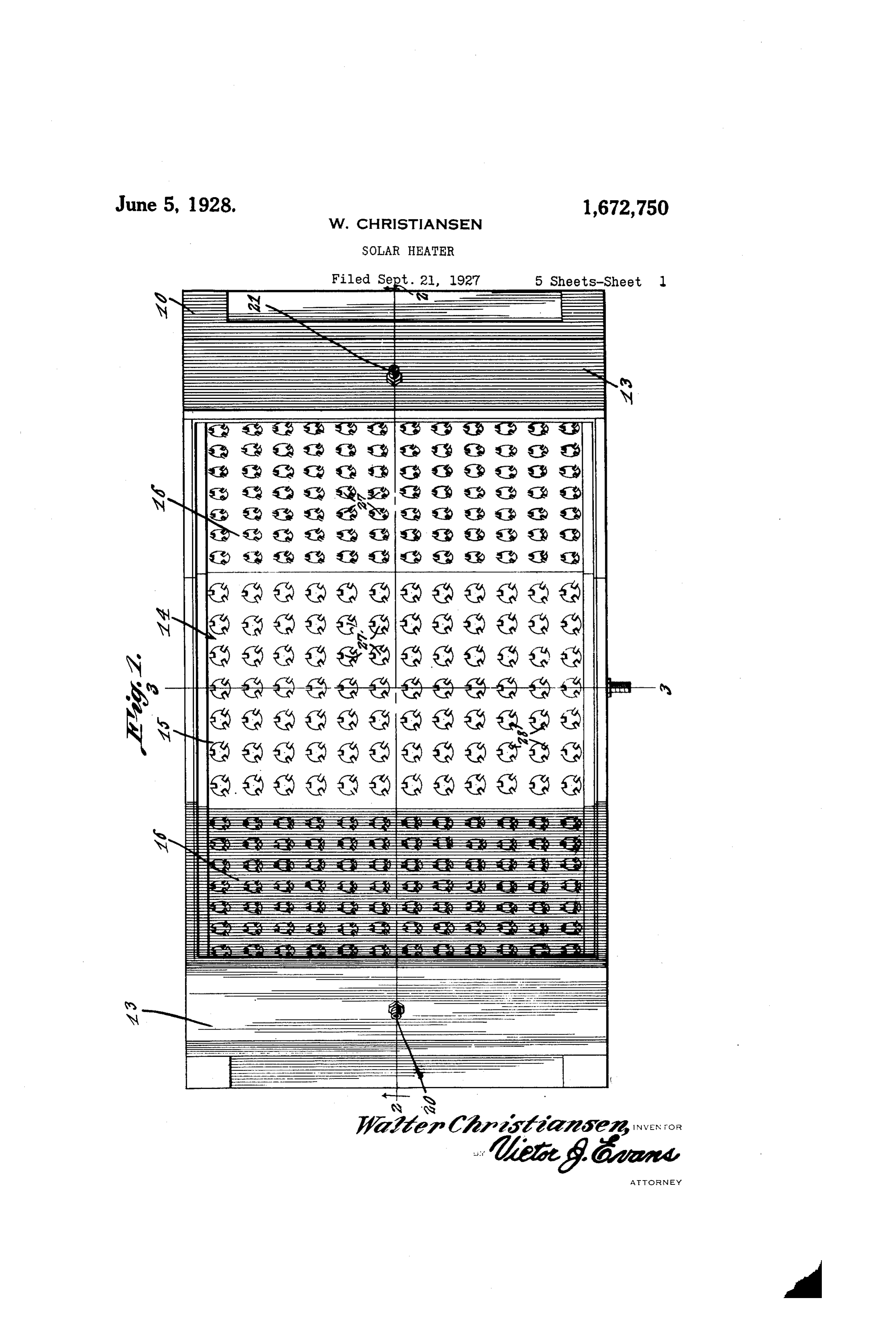
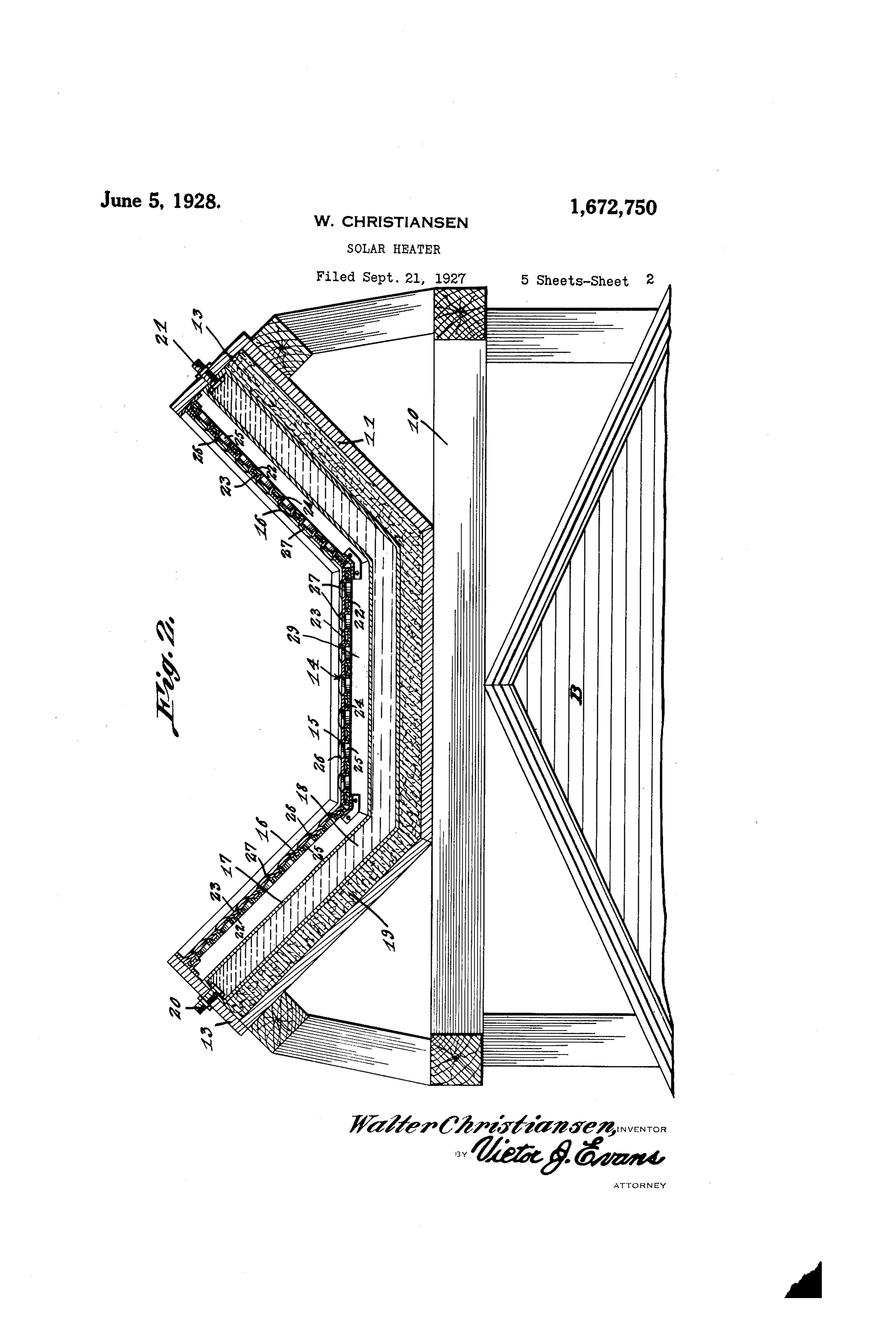
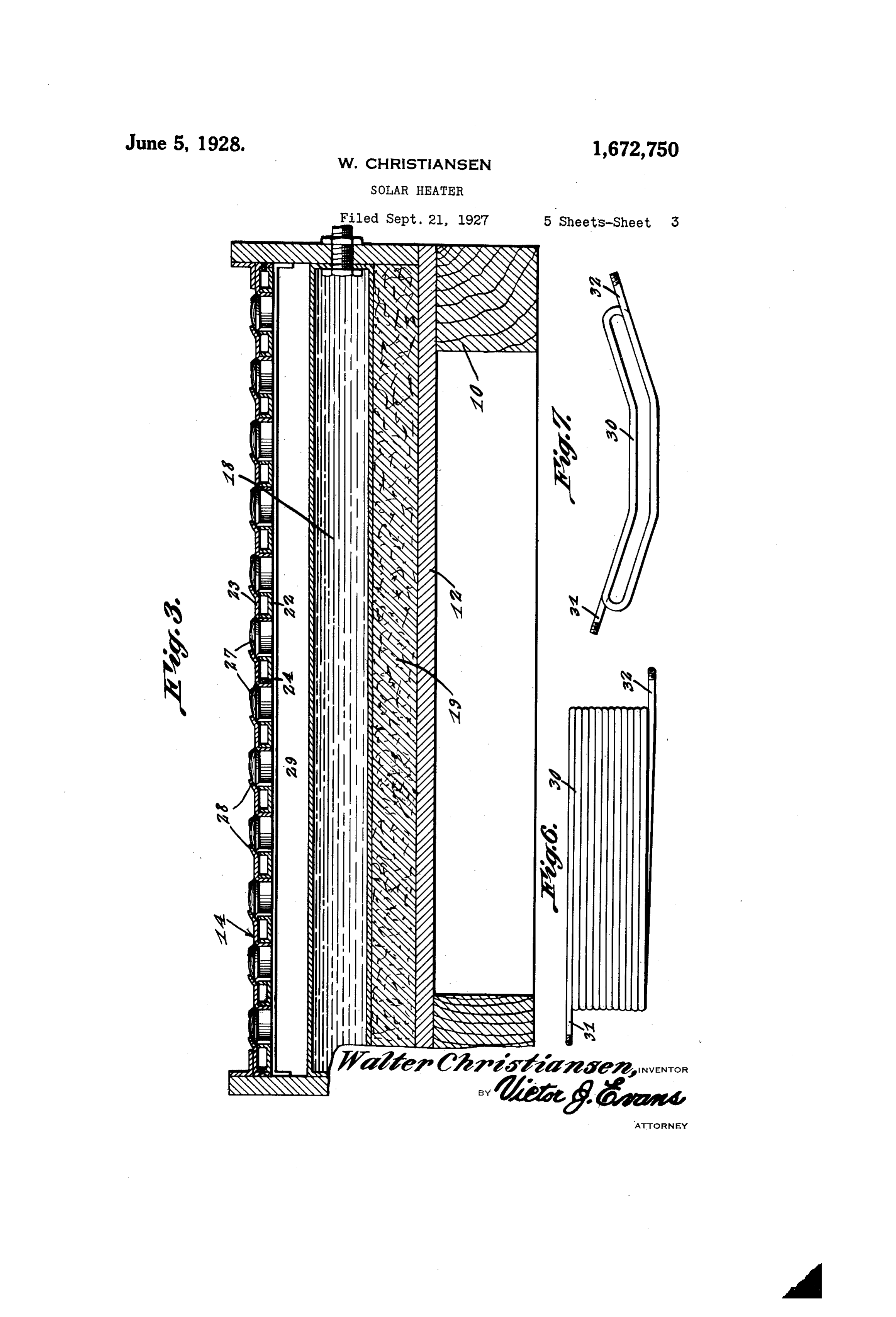
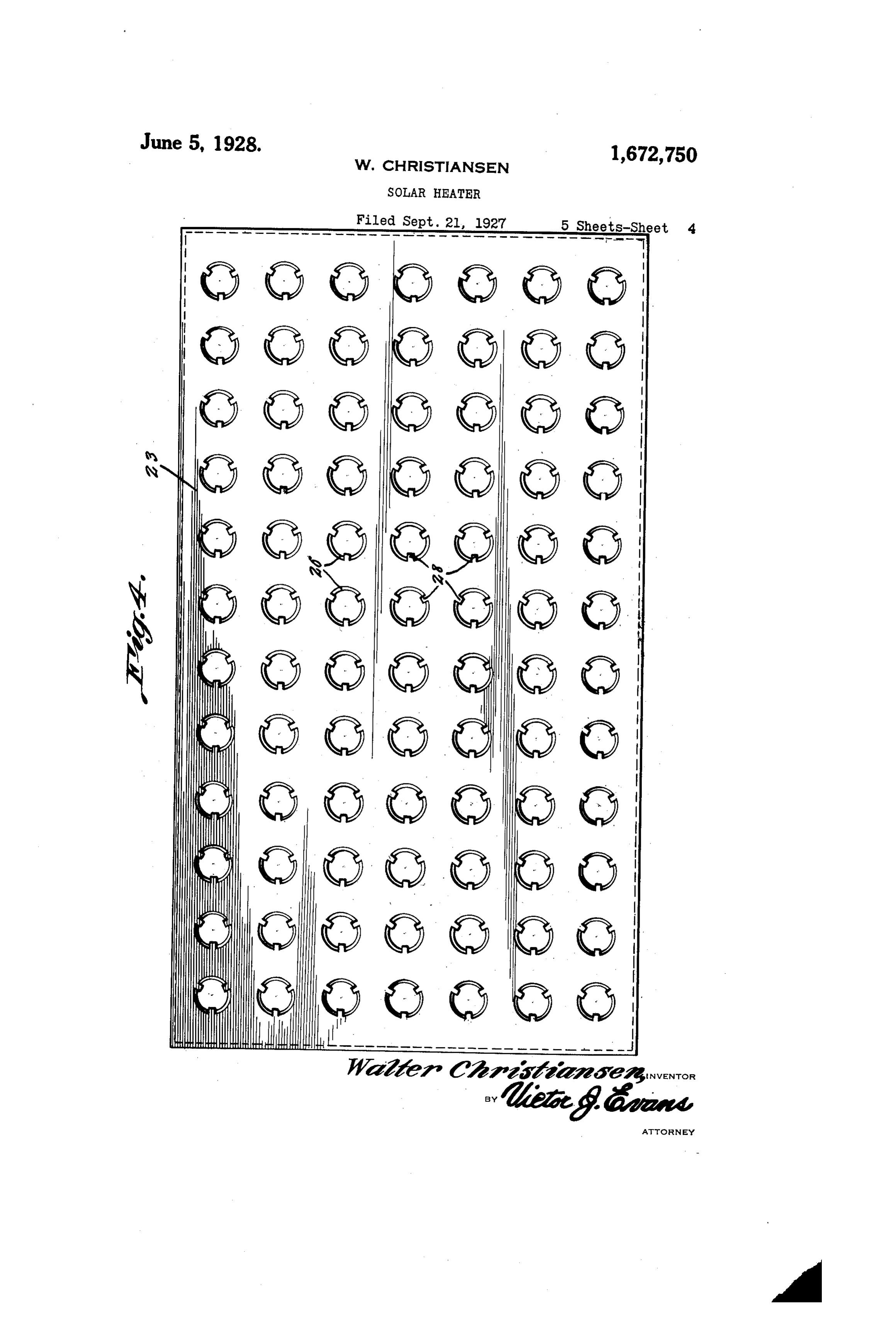
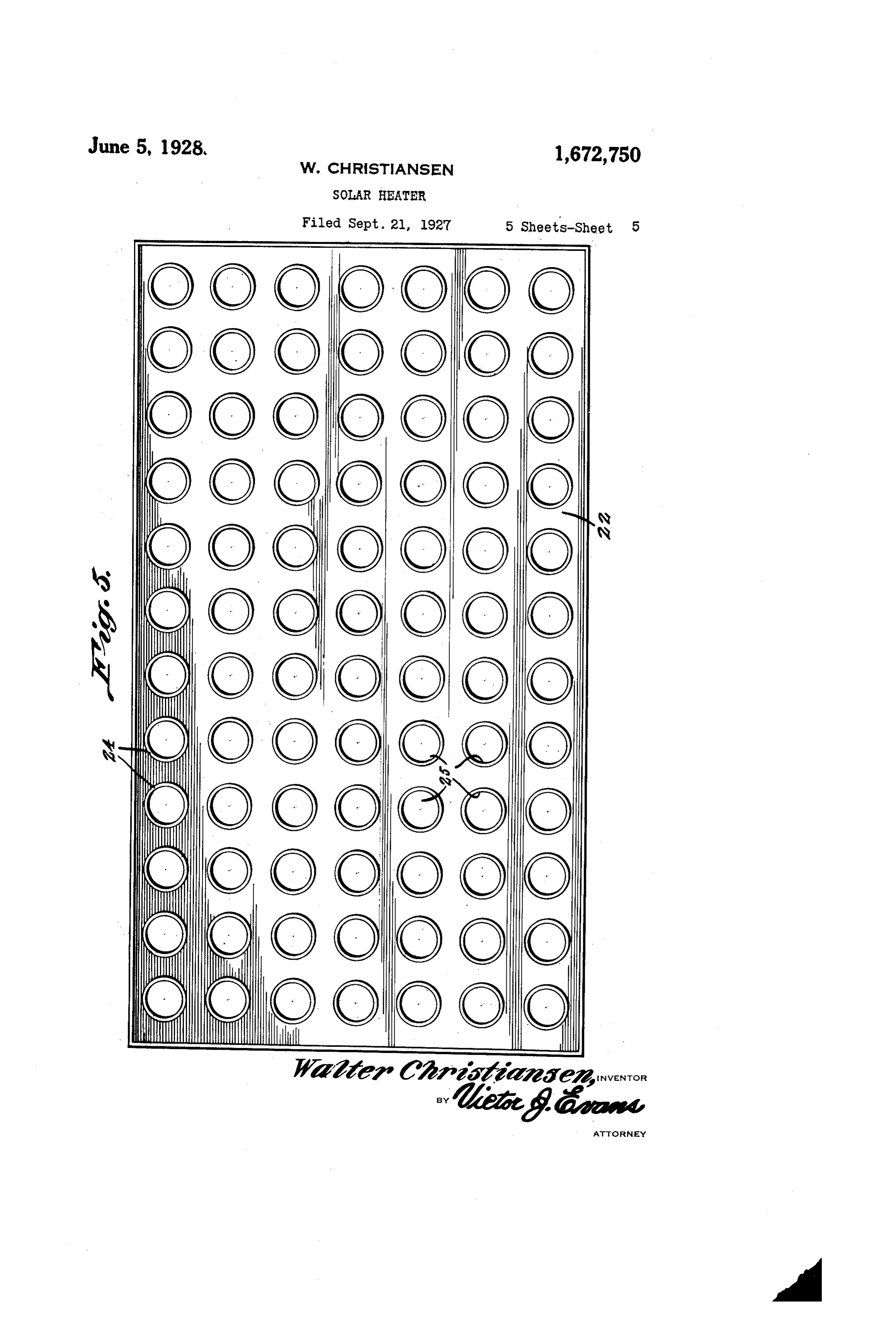
This invention relates to heaters, an ob Iocated beneath and spaced from the top ject being to provide means for utilizing wall 14 is a receptacle 17. This receptacle the heat of the sun rays for heating Water. is preferably of the same configuration as Another object of the invention is the the top wall 14 and is adapted to contain water or other liquid 18. Located within provision of a heater of this character which the is constructed of sections arranged so that housing between the bottom of the wall 30 one or more sections will be positioned trans of the receptacle 17 and the bottom wall 12 versely of the direct rays of the sun as the of the housing is a lining of heat insulating. latter travels across the horizon, together material 19. The receptacle is provided with means for directing the Sun's heat with an inlet 20 and outlets 21 and these 65 upon a receptacle or container for Water. Or inlets and outlets may be connected respec other liqui and to provide a circulation tively with a suitable source of water sup through the receptacle. . . . ply and with receptacles or the like to With the above and other objects in view, which the heated water may be conducted. the invention further includes the follow The top wall 14 is of novel construction, 70 ing novel features and details of construc inner each of the sections being formed of an tion to be hereinafter more fully described, panel 22 and an outer panel 23. illustrated in the accompanying drawings These panels are provided with openings and pointed out in the appended claims. which are surrounded by flanges 24, the 2 In the drawings:- d flanges 24 of one of the panels being tele 5 Figure 1 is a top plan view of a solar scopically received within the flanges 24 of heater constructed in accordance with the the other panel. Passages 25 are thus pro present invention. vided through the top wall 14. Located at Figure 2 is a sectional view on the line the outer ends of these passages are seats 26 25 2-2 of Figure 1. which receive magnifying lenses 27, the lat Figure 3 is an enlarged section on the ter being held in place by fingers 28 which 80 line 3-3 of Figure 1. extend from around the edges of the open Figure 4 is a top plan view of the outer ings of the outer panels. The wall 14 is panel of one of the top wall sections. spaced from the top wall of the receptacle 3. Figure 5 is a plan view of the inner panel 17 and this space provides a heat chamber of one of the top wall sections. 29 with which the passages 25 communicate. Figure 6 is a detail plan view showing a An unobstructed passage for the sun's heat different form of liquid receptacle or coil. from the lenses 27 is thus provided for the Figure is a side view of the coil shown upper wall of the receptacle 17, so that 35 in Figure 6. water within the said receptacle may be Referring to the drawings in detail heated within a relatively short time. By 90 wherein like characters of reference denote reason of the relative angles of the sections corresponding parts, the heater which may of the top wall 14, a maximum amount of be placed in any advantageous position, is this wall will be presented to the rays of 40 shown as supported upon the top of a build the sun as the latter moves over the hori ing, a portion of which is indicated at B. Zon while heat within the chamber 29 may 95 The heater comprises a supporting frame circulate through this chamber over the 10 and a housing 11, the latter being of surface of the receptacle even though one of . suitable configuration. This housing com the end panels 16 is not exposed to the di 45 prises a bottom wall 12 and side walls 13. rect rays of the sun.
The top wall of the housing is indicated at If desired, a coil such as is indicated at OO 14 and is shown as comprising a horizontal 30 in Figures 6 and 7 of the drawings may section 15 which has extending from its op be substituted for the receptacle 17. This posite edges, oppositely inclined sections 16. coil includes an inlet 31 and an outlet 32 50 The sections 16 are arranged at a suitable distribution.
for connection with sources of supply and 05 angle, the purpose being to provide a maxi mum amount of surface for exposure to the The invention is susceptible of various sun's rays irrespective of the position of the changes in its form, proportions and minor sun, and within a relatively small area. details of construction and the right is here.
Page 7
in reserved to make such changes as proper cle and bottom wall of the housing, and ly fall within the scope of the appended lenses arranged within the sections of the C.S. top wall of said housing.
Having described claimed is:- the invention what is 4. In a sun power heater, a housing, a top 45 wall for the housing, said wall including 1. In a sun power water heater, a housing, sections arranged at different angles, where a top wall for the housing, said wall includ by one or more of saidsections will be po ing sections arranged at different angles, sitioned transversely of the direct rays of whereby one or more sections will be si the sun as the latter travels across the hori . O tioned transversely of the direct rays of the zon, a receptacle located within the housing sun as the latter travels across the horizon, beneath the top wall and being spaced from a receptacle located within the housing be said wall to provide a heat chamber, a heat neath the top wall, a heat insulating linin insulating lining between the receptacle and 55 between the receptacle and bottom wall o bottom wall of the housing, and lenses ar 5 the housing and lenses arranged within the ranged within the sections of the top wall section of the top wall of said housing. of said housing.
2. In a sun ower water heater, a hous 5. In a sun power heater, a housing, a top ing, a top wall for the housing, said wall wall for the housing, said wall comprising including sections arranged at different an spaced inner and outer panels having open 20 gles, whereby one or more sections will be ings therein, flanges surrounding the open positioned transversely of the direct rays of ings, with the flanges of one panel telescopi the sun as the latter travels across the hori cally received within the flanges of the other zon, a receptacle located within the housing panel and providing heat passages, seats at beneath the top wall, a heat insulating lin the outer end of the passages, lenses upon ing between the receptacle and bottom wall the seats, means engaging the lenses to hold of the housing, and lenses arranged within the latter in position, a receptacle within the section of the top wall of said housing, the housing and an insulating lining be the inner faces of the lenses being opposed tween the Éto of the receptacle and the 70 to the top of the receptacle to provide an 30 unobstructed passage of heat through the bottom of the E. 6. In a sun power heater, a housing, a top lens to the receptacle. wall for the housing, said wall comprising a 3. In a sun power water heater, a hous horizontal section and oppositely inclined ing, a top wall for the housing, said wall in sections extending from the horizontal sec
cluding sections arranged at different an tion, a receptacle located within the housing" gles, whereby one or more of said sections beneath the top wall, a heat insulating lin will be positioned transversely of the direct ing between the receptacle and bottom wall rays of the sun, as the latter travels across of the housing and lenses arranged within the horizon, a receptacle located within the the sections of the top wall of said housing.
housing beneath the top wall and having In testimony whereof I affix my signature. the same configuration as said top wall, a heat insulating lining between the recepta WALTER CHRISTIANSEN.
Provenance
- Collection
- Cited prior art
- Original PDF
- patentimages.storage.googleapis.com →
- Filed
- 1927-09-21
- Pages
- 7
- Method
- pdftotext (the PDF's own text layer) + pdftoppm 300dpi page scans
- Source
- Google Patents bibliographic record
- Granted
- 1928-06-05
- Inventors
- Christiansen Walter
- Transcribed from
- patentimages.storage.googleapis.com →