patent · US4172740
Solar energy system
30 October 1979
Page 1 — bibliographic record
United States Patent (19) o 4,172,740 Campbell, III 45) Oct. 30, 1979
(54). SOLAR ENERGY
SYSTEM 33; 6/ E. El Jr. ...........................
(76) Inventor: William P. Campbell, III,3310 3,866,285 2/1975 Clark .................................. 29/157 R Rowland Pl., N.W., Washington, 3,934,573 1/1976 Dandini................................ 126/270 D.C. 20008 3,960,136 6/1976 Moan et al. ....... ... 126/271 3,988,166 10/1976 Beam ............. . . 136/89 * Notice: The portion of the term of this patent 3,990,914 1/1976 Weinstein et al. . . 136/89 E. to Mar. 28, 1995, has been 4,081,289 3/1978 Campbell ............................. 126/271
Primary Examiner-Leland A. Sebastian 21 Appl. No.: 890,935 Attorney, Agent, or Firm-John S. Roberts, Jr.
22 y 57 ABSTRACT Related U.S. Application Data A system for extracting energy from the sun's rays 63 continuation-in-part of ser. No. 644,159, Dec. 24,
including a bank of solar energy cells which generate electrical current when exposed to the rays of the sun, 2 immersed in a bath of liquid formed to serve as a lens 51 Int. Cl.’..................... H01L 35/02; He; C; concentrating the sun rays on the cells, and transmitting
heat away from the cells. The cells are shaped so as to cause a trapping effect of radiation. incident thereon.
58 Field of Search ........................... 1367206, 89 pc. The improved solar converting unit additionally in 126/270,271 cludes a method for preheating the interior thereof. The converting unit is preferably equipped with light gath 56 References Cited Eg is focusing means thereby providing coherent
2,402,662 6/1946. Ohl ......................................... 136/89 2,946,945 7/1960 Regnier et al. ........... 33 Claims, 13 Drawing Figures
Page 2
Drawing sheet — no readable text.
Page 3
Drawing sheet — no readable text.
Page 4
Drawing sheet — no readable text.
Page 5
there is no further relevance of the Wallace reference to
SOLAR ENERGY SYSTEM the present invention.
This is a continuation-in-part of Ser. No. 644,159 filed SUMMARY OF THE INVENTION Dec. 24, 1975 now U.S. Pat. No. 4,081,289 entitled This invention relates to a novel system for extracting Solar Energy System. energy from the sun's rays, which utilizes the best tech BACKGROUND OF THE INVENTION nology of the prior art in such a way as to increase efficiency to that more nearly approximating the theo
The continuing deteriorating condition of our plan retical maximum levels of energy extractable from the et's ecosphere caused primarily by the entropy of fossil 10 sun's rays, surpassing that heretofore possible in the fues for transportation, electrical production, heating prior art.
and cooling, etc., and the ever increasing cost of these This invention provides a system which utilizes the ancient hydrocarbons due to dwindling supplies, have extractable electrical potential in the sun's rays in com made the search for new energy sources imperative for bination with the extractable thermal properties of the our future health and well being. 15 sun's rays. The inherent optical properties of the liquid Solar energy for years has proved itself reliable, non or gas used to receive and transmit the heat energy polluting, and abundant energy source capable of meet generated by the system are utilized to focus the rays of ing our increasing energy needs for millenia. However, the sun.
until recently, it has been little exploited due to the This invention also provides a system which increases seeming abundance of low cost fossil fuels. 20 the extractable electrical energy capability of prior art
In addition to the economic problems, the slow de radiation velopment of solar generated energy can be attributed amount ofcells by providing a means to concentrate the to the numerous technical problems with solar convert same time, providingimpinging sunlight on the cell while, at the ing equipment; the need for recoating the infrared ther the cell, thereby eliminating thepreclude means to overheating of mal conversion layer because of ultra-violet breakdown on prior art cells so that it may be operatedlimitation
at much and oxidation; the need for a collector drain down sys higher energy input levels than heretofore possible. tem or anti-freeze; heat exchangers; the need for the separation of the fluid and potable water due to contam ingThe invention further provides a system for extract thermal energy from the sun's rays in a far more ination; back-up auxiliary heating units; high quality efficient manner than the prior art by providing means insulation, prevention of convective and radiant heat 30 to focus the loss through collector and storage system; the need for the panel, bysun's rays on the heat-absorbing portion of forming the heattransmitting medium in a outside power necessary for pumps and controls, track geometric configuration which will accomplish such ing motors, etc., and heat losses in transfer between the focusing.
collector and storage. There is also the need for suffi cient Delta-T on low solar output days to perform use 35 In a preferred embodiment, the invention comprises a ful work. transparent container configured as a body of rotation. Radiant energy converting cells are disposed in the
The following disclosure will make apparent to those container at the focal point of the body of rotation, for skilled in the art of a method for overcoming these the direct extraction problems with a new and novel means. of electricity from the sun's rays. A thermal transfer medium filling the container focuses
THE PRIOR ART STATEMENT rays of the sun on the cells to increase efficiency and to Applicant is aware of the following patents in the extract and transmit heat from the cells. Means are prior art: U.S. Pat. No. 4,026,267; Coleman U.S. Pat. provided to circulate this thermal transfer medium in the container and to transmit cold medium to the con
No. 3,279,457; Kyryluk U.S. Pat. No. 2,989,575; tainer and heated medium from the container. Wallace U.S. Pat. No. 2,312,920; Litton U.S. Pat. No. 45 Wave-like converter substrates increases the conver
These references represent the best known prior art sion of the sun's rays by causing light to reverberate known to the applicant. Of these the Coleman patent before allowing it to re-emit. Therefore, a substantial comtemplates the use of fiber optic material for the portion of radiant incident on the surface has a reflected concentration of solar energy. However, it does not 50 component face.
that impinges on other portions of the sur disclose the use of a vacuum for insulation or a method of liquid optical focusing. The Kyrylukpatent discloses Many of the embodiments herein disclosed are insu a spherical embodiment in FIG. 3 of a solar heat con lated with a vacuum system, preventing convective centrator which, geometrically, similar to one embodi heat losses. Furthermore, due to the superiority of a ment of the applicant's invention; however, there is no 55 vacuum cavity and the large collector mass, the need intention of incorporating solar cells or a liquid within for anti-freeze or collector drain-down systems is elimi the sphere. The two Abbot patents disclose solar heat nated. This solar converting model when incorporating ers utilizing glass envelopes around a heat, absorbing heater means demonstrates a high level of simplicity by tube. These references do not contemplate utilizing a incorporating the back-up auxiliary heater within the liquid within the envelope. The Wallace and Litton collecting unit, making it a complete one unit system. patents relate to solar cells, the Litton patent specifi A unique aspect of several of the models discussed cally relating to cooling system or jacket for solar cells. herein is by allowing the ultraviolet rays of the sun to The Litton patent does not contemplate the use of liquid pass through the stored water, an inherent property of coolant for focusing the sun's rays nor does it contem sunlight produces a purifying effect. This effect has also plate utilization of the coolant as a source of energy 65 been shown to break down many harmful chemicals itself. Wallace is pertinent only in that it discloses in the commonly found in municipal water supplies. This, embodiment of FIG. 8 thereof a spherical substrate for combined with the fact that antifreeze is not used in the the solar cells. Other than the geometrical similarity, system, removes the possibility of contamination (in
Page 6
fact, it leaves the water in a superior condition), thus The object of the apparatus described in the present removing the necessity for heat exchangers. application is to concentrate the sun's rays into an array Another major problem encountered with all know of radiation responsive cells thereby increasing the cells solar collecting units is the photo and oxidation break output and decreasing their per watt cost. Furthermore, down of the infrared converting coating. While no 5 these cells due to the contours of their geography will, known substance can stand up to such conditions indefi irregardless of what radiation responsive system is used, nitely, we have found that the use of multicoatings produce a substantial power increase may be obtained, greatly extends its life. An example of such a coating compared to the power from the same linear area using would consist of layers of bonding material alternating the same material of standard design. Heat is then re with layers of infrared converting means (such as gran 10 moved from the cell which can be made to do useful ular carbon, black nickel or the like) so as to produce work or can be stored for later use. multi-layered composition. Thus, with time, when one This design allows the concentrated sunlight to pass layer of bonding material breaks down, it releases the first through the thermal transfer medium before it infrared converting material and exposes the underlying strikes the collecting material. This thereby transfers layers, permitting the unit to continue operation for a 15 more heat to the fluid, regardless of what collecting longer time. material is used, because a portion of the radiation is In the preferred embodiment, the unit would contain converted to heat directly in the fluid itself before it hits radiation responsible means, such as photovoltaics, the collecting surface.
thermal electric, and the like, which produce an electric Another very important prior art device for extract current when exposed to the rays of the sun. This elec ing energy from the sun's rays is the solar energy panel tric current could then be made to perform useful work or cell which utilizes properties of material such as (powering tracking motors, sensors, etc.) necessary for silicon, cadmium sulfide, or selenium which, when con the unit's function, and further providing electric en tacted by the sun's rays, emit electrons displaced by ergy for other uses as well. photons in the sun's rays to thereby generate electrical Transfer medium may be provided for the circulation 25 current. This type of device has found wide utility in of an appropriate fluid electronic junction material re present day industry, particularly in space where such quired for the production of an electric output from a cells power satellite systems of various types. A greater source such as, for example, photovoltaics. This action heat transfer of the cells is provided because thermal thereby extends the radiation ionic converter's life by 30 energy is being transferred to the fluid on both the front cooling and replacing spent barrier material. Addition and rear sides of the converter substrate, doubling the ally, the surface electrode can be eliminated by using a area which already-by use of corrugated surfaces-con fluid of a junction material with electric and thermal tains greater collecting areas.
conductive properties. This vessel, containing the cell array and transfer Auxiliary heater means are submerged in the collec 35 fluid in a spherical or cylindrical shape, forms a focus tor maintains a minimum collector temperature, allow ing lens almost completely surrounded by an evacuated ing collection of useful energy on low solar output days space and outer wall which eliminates convective heat when the traditional collector would not be able to loss.
function due to insufficient Delta-T.
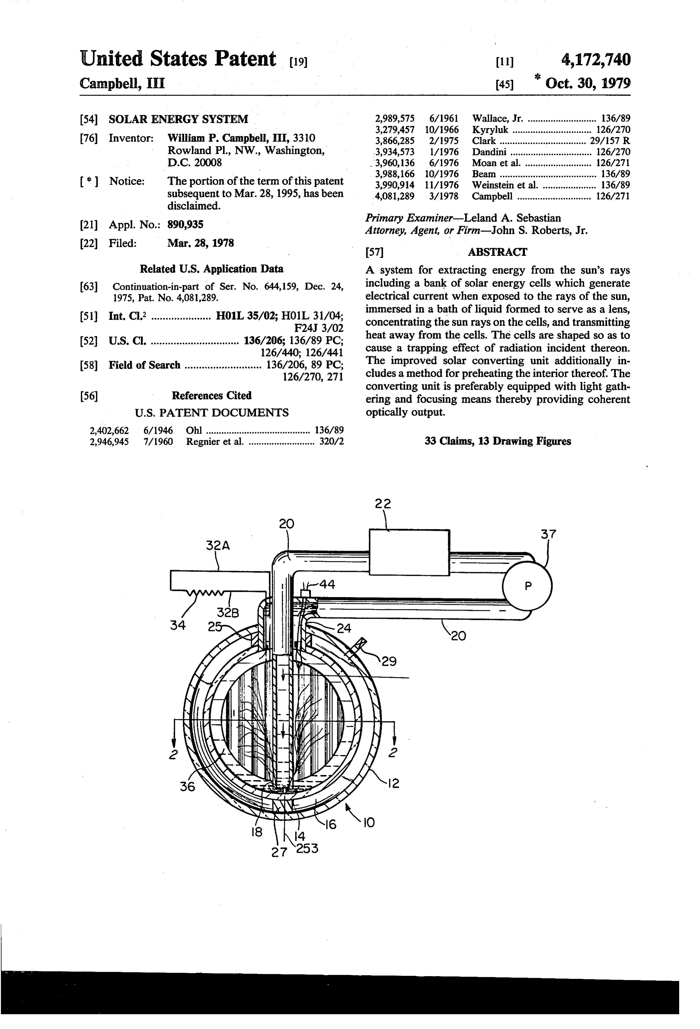
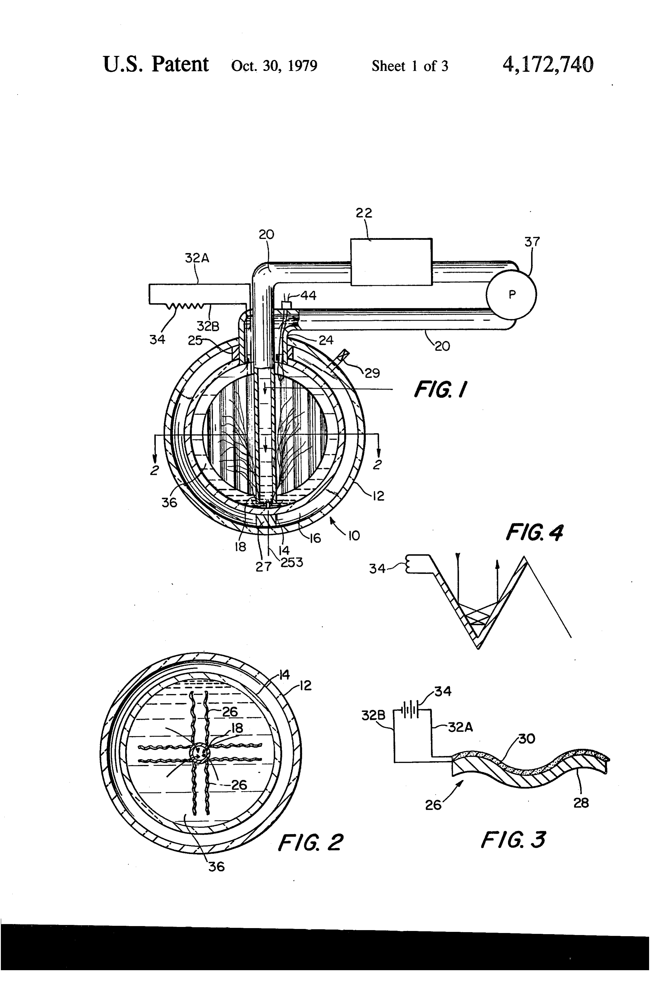
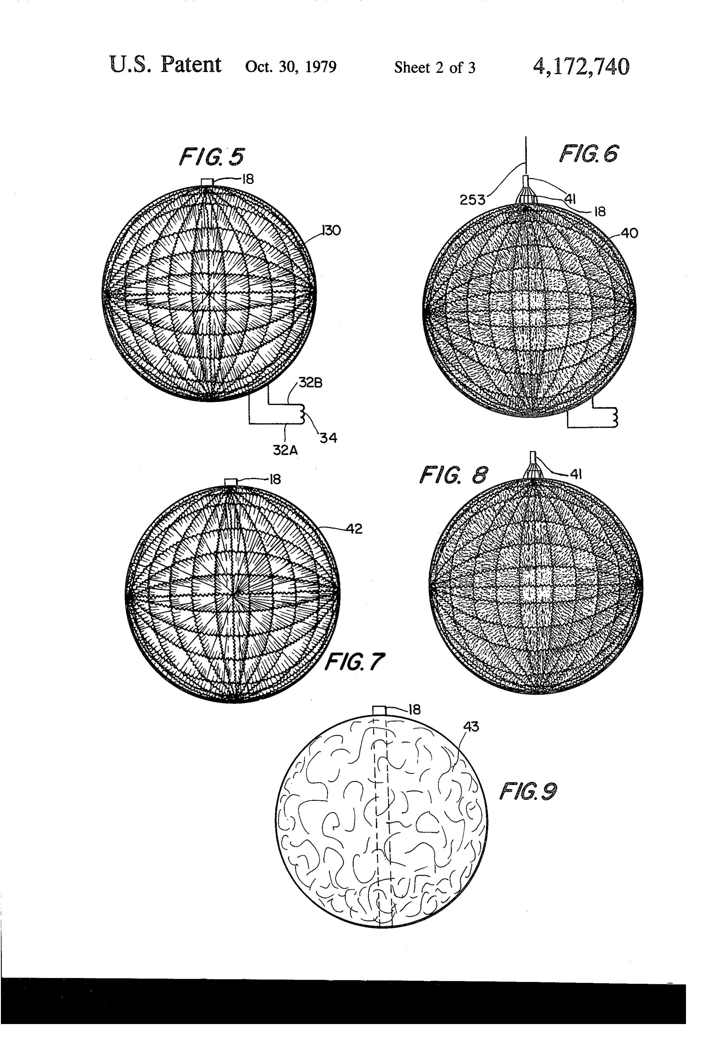
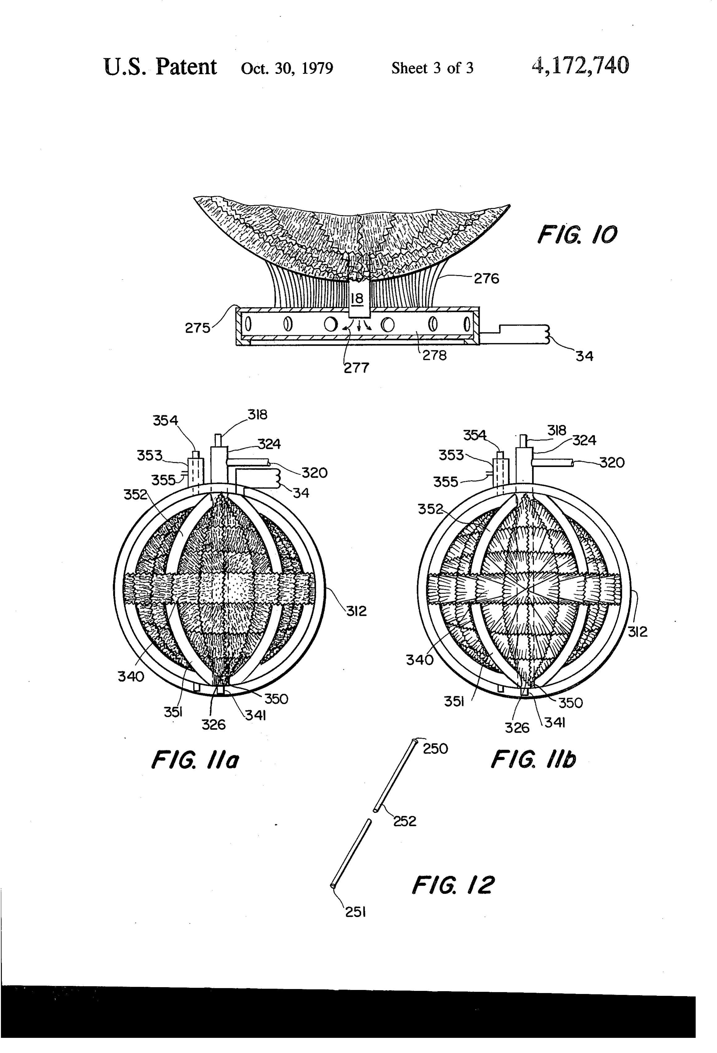
As an example, let us say that on a given day of low A BRIEF DESCRIPTION OF THE LORAWINGS solar output, a traditional collector raises its plate and FIG. 1 is a sectional view in elevation of a device in collector fluid from 50 F. to 90' F.-a 40 rise in tem accordance with the invention; perature, but since the storage system is at, let us say, FIG. 2 is a sectional view of the embodiment of FIG. 110F., the system is unable to perform useful work this 1 taken along the line 22 thereof; day. However, on this same day, our collector-due to 45 FIG. 3 is an enlarged fragmentary sectional view of a the fact that the collector and storage system is main portion of the device of FIG. 1; and tained at 110 by the heater thermostat unit-is there FIG. 4 shows a radiant energy electric converting fore able to raise its temperature to 125 with the avail cell with light trapping configurations. able solar radiation, thereby performing useful work. FIG. 5 illustrates an interchangeable module contain Among the leading types of devices for extracting 50 ing radiant energy electric converting cells. energy from the sun's rays are solar heating panels FIG. 6 shows an interchangeable module containing which utilize the energy present in the infrared portion radiant energy electric converting cell with light gath of the sun's rays to raise the temperature of a liquid such ering and concentrating means. as Water. FIG. 7 illustrates an interchangeable module incorpo The prior art is replete with solar heat devices gener 55 rating infrared converting means. ally including means to focus the sun's rays through FIG. 8 shows an interchangeable infrared converting mirrors and reflecting bodies, and with heat absorption module with light gathering and concentrating means. surfaces utilizing the energy in the infrared portion of FIG. 9 shows an interchangeable infrared converting the spectrum to maximum efficiency. These heat cells module additionally reducing convective circulation. generally comprise a transparent surface with a black 60 FIG. 10 shows an interchangeable module with a body heat absorption surface in parallel spaced relation radiant electric cell and fiber optic concentrating thereto with the liquid to be heated transmitted between C2S these surfaces in heat conductive tubing of copper, FIG. 11a shows an internally circulated solar con aluminum, or the like. The developments in these sys verter with radiant energy electric converting means tems include means to move the panel or cell to track and light gathering and concentrating means. the sun and/or means to fucus the sun's rays on the FIG. 11b is the same device as 11a but without elec panel through parabolic mirrors set up in appropriate tric converting means and light gathering means. relation to the panel. FIG. 12 shows a fiber optic lasing element.
Page 7
The unit may further be equipped with an optional manifold 350 fluid is subdivided into the appropriate auxiliary heating means 44, which helps to maintain a number of conduits 351 corresponding to the number of more constant temperature, thereby overcoming many panels 326. Along conduits 351 are spaced holes facing problems encountered with traditional concentrator corrugated panels and situated so as to emit water to systems. The auxiliary heating means additionally pro channel created by two corrugated panels laid together vides back-up heat for times of insufficient solar output, inversely and bonded.
allowing the device to continue operations. Thermal conducting fluid convects upward in the Another important feature of heat element 44 is the interior of panel 326 to conduits 352 where fluid enters decreased amount of time necessary to bring the unit up via spaced holes and culminates at manifold 324. Heated to operating temperature by maintaining minimum tem O fluid is then removed from the unit via pipe 320. perature at times of inactivity. A problem with heliostat Fiber optic concentrated means 340 is similar in con central collector units (to which this unit is most adapt struction to the converting unit, as shown in FIG. 6. able) of known art, is a tendency to degrade due to Fiber optic material extending out radially from the extreme fluctuations of temperature created by the junctions of panels 326 where the fibers culminate and magnification of a changeable light source, the sun. By 15 bend toward optical end piece 341. End piece 341 is maintaining minimum temperature heating element 44 is clear or partially mirrorized to produce reverberation helpful with this problem, also, as it prevents the unit between it and the slightly more reflective coating at from flash heating from low temperature. the other end of the fiber, thus producing alasing effect. Furthermore, since the collecting means is immersed in the heat transfer medium, it has twice the surface area 20 When adequately illuminated, a coherent beam will to remove heat from since it removes thermal energy The unitfrom emerge
341, which may then perform useful work.
described is then complete, but may be from its front surface as well as the rear; the transferred enclosed within a transparent sperical container. medium therefore remains at substantially the same The container, depending on size, could be composed temperature on light exposed and shadowed sides of the from geometric sections collector, thereby preventing internal stresses from 25 tainer. The interior of theofsphere a transparent spherical con is either evacuated or occurring.
With the aforementioned structure complete, the filled with dry non-reactive gas or irradiant gas such as interior of the housing formed by the inner shell 14 is xenon. Optional manifold 353 can introduce, evacuate filled with a suitable transfer medium 36 such as, for or circulate the atmosphere within the sphere through example, water, xenon, gas or the like. 30 pipes 354 and 355. Should an irradiant gas such as xenon Pump means 37 are provided in the conduit 20 to be within the sphere when a high intensity electro-mag circulate the Liquid 36 from the manifold 24 to the tube wouldbeam netic enters (such as micro-wave), a brilliant flash occur. This flash would pump the radiation con
In operation, the device is exposed to the rays of the wouldverting means to high output levels. Further, the flash sun. The rays of the sun penetrate the transparent shells 35 intimatepulse the fiber lasing means with which it is in contact. In this manner the unit could continue 12 and 14, and are focused by the transfer medium 36 to function in times of no light if it were illuminated by within the inner shell onto the solar panels 26, where upon radiant energy is converted and extracted from achronous microwave source. Such a source could be a geo-syn the device 10 through the leads 32A and 32B while convertedorbiting solar converting station transmitting energy in the form of microwaves to earth.
thermal energy is extracted through manifold 24. The Another source could be high altitude ballons with sun's rays impinging on the solar panels also raises the temperature thereof, thereby heating the interior of the solar as converting means transmitting energy in same shell 14. The insulation provided around the shell 14 by The solar device as shown in FIG. 11B is constructed the evacuated space 16 holds the heat generated within according to the device in FIG. 11A, but does not con the shell, thereby raising the temperature of the transfer 45 medium 36. Circulation of the transfer medium by the tain radiation converting means or fiber optic concen pump means 37 provides withdrawal of heated transfer trators. It, therefore, functions as strictly a thermal unit. While the invention has been herein shown and de medium through manifold 24 from the top portion of the inner shell 14, and entry of cooled transfer medium scribed in what is presently conceived to be the most through the manifold 24 via tube 18 to the bottom of the 50 practical and preferred embodiments thereof, it will be shell. Heat is removed from the circulated medium 26 apparent to those of ordinary skill in the art that many by the load 22. The circulation of the medium thereby modifications may be made thereof within the scope of provides for removal of useful heat from the device 10 est the invention, which scope is to be accorded the broad and, at the same time, for cooling of the solar cells 30. interpretation of the appended claims so as to en The presence of the transfer medium 36 within the inner 55 compass all equivalent structures and devices. What is claimed is:
shell 14 further provides for optical focusing of the Sun's 1. Solar radiation converting apparatus comprising rays on the solar panel 26.
solar radiation responsive means for transforming inci
DISCLOSURE OF A PREFERRED dent radiation into another energy form, a pair of EMBODMENT spaced transparent housing members with complimen The solar device shown in FIG. 11A and B is de tary curved surface, said members defining a fluid tight signed to incorporate all the radiation converting means volume with said radiation responsive means within as disclosed within this document. Resembling the unit said volume, and means for circulating fluid into, in FIG. 1, this unit's main difference lies in the enclosure through, and out said volume so that said solar radiation of the circulating means. ... . . responsive means are cooled and said fluid is heated. In operation cool liquid would enter unit along pipe 2. Apparatus as recited in claim 1 wherein said solar 318 passing through center of manifold 324 extending radiation responsive means comprise a central support, up through the center at junction of panels 326. At a plurality of surfaces extending generally radially out
Page 8
DESCRIPTION OF A PREFERRED
permits the gathering of and focusing of light through
EMBODIMENT the use of fiber optics material, which extend out radi ally from the unit so as to accomplish 360 collection.
In FIG. 1 the device shown generally at 10, com Light is then channelled through the fiber optic mate prises a body of revolution defining a sphere. The de 5 rial to optic boule 41, where all fibers converge, the vice is formed of a pair of shells, outer shell 12 and inner ends of 41 being polished as well as the extreme ends of shell 14, mounted in spaced relationship and affixed 40. Another construction would employ partial mirror together to form a gas-tight space 16therebetween. The coatings on the ends of fiber means 252 as is shown in space 16 is evacuated to provide an insulating medium FIG. 12. Being less reflective coating 251 at 41 will between the shells 12 and 14 to insulate the interior of 10 thereby emit radiation more readily than at the end 250 the container formed thereby. The shells 12 and 14 are at 40. When adequately illuminated the fiber means 252 formed of some transparent material such as, for exam will produce a lasing effect 253, thus permitting the unit ple, glass or the like. to have electrical, thermal, and optical outputs. A central tube 18 is disposed along the axis of the FIG. 7 is a module constructed as is shown in FIG. 5; housing formed by the shells 12 and 14, exiting at the 15 however, the apparatus in FIG. 7 contains no electric top end thereof and connecting with a conduit 20 con converting means and is instead coated with infrared nected to some load 22 such as a storage device. The reconverting material 42, and functions strictly on a conduit 20 then returns to the device 10 entering the thermal basis.
housing formed by the shells 12 and 14 in an outlet The apparatus in FIG. 8 shows a design similar to manifold 24, concentrically disposed with respect to the 20 FIGS. 6 and 7, wherein the thermal and optical proper tube 18. As is best seen in FIG. 2, a series of corrugated ties of sunlight are used as herein disclosed, but no elec panels, 26, preferably are mounted on the tube 18 ex tricity is produced within the unit. tending radially therefrom toward the wall of the inner FIG. 9 shows infrared converting material 43 resem shell 14. Preferably occuring at about 30 intervals longi bling wadded cottom or insulating material, with infra tudinally and latitudinally, the panels 26 are semicircu 25 red converting coating. Material converts radiant en lar in configuration and are sized to conform closely in spaced relationship to the inner surface of the shell 14. ergy into useful thermal energy, and also helps to retain Exact angles and dimensions are not to be limited by the heat by decreasing internal convective circulation. The embodiment shown in FIG. 10 provides appara above descriptions.
As is best seen in FIG. 3, the panels indicated gener 30 tus to channel high concentrations of radiation as herein ally there at 26 are composed of a corrugated substrate disclosed to the surface of a radiation conversion cell 28 of some suitable material such as aluminum, glass, 278 for the purpose of increased extraction of electricity or other useful energies. In operation radiant energy is plastic, or the like. Superimposed on the substrate 28 are transmitted to transparent manifold brackets 275 by radiant energy converting means 30, composed of a suitable material, such as, for example, selenium, silicon, 35 fiber optic means 276 in the manner herein disclosed. infrared converting means of the like, as is well known fiber Manifold 25 maintains a certain distance between the in the art of solar cell, thermo-electric and solar energy optic means thereby permitting the circulation of conversion. The cell 30 is preferably composed of radia thermal transfer fluid across its surface from inlet junc tion converting means in corrugated sheet form and tion 18.
adhered to the substrate 28. Electrical leads 32A and Concentrated radiation from fiber optic means passes 32B are connected to the cell 30 and to and electrical through the transparent bracket and transfer medium load 34, for example, such as a storage battery of the striking the radiation converting means, such as, for like. However, solar cells are not necessary to the func example, photovoltaics, thermoelectrics and the like, tion of the device is strictly a thermal unit. thereby producing useful extractable energy. Shown in FIGS. 5, 6, 7, 8, 9, and 10 are means for 45 Circulating thermal transfer medium may consist of modifying the energy output of the unit with interchan any suitable substance, but preferably contains fluid gable modular radiant converting means. electronic junctions with electrically conducting mean FIG. 5 shows the interchangeable module consisting 277 thereby provides the means for replacement of of a ridged, corrugated panel substrate 39 (preferably spent junction material and elimination of the surface with thirty degree corrugations) which extends out 50 electrode when the poles are suitably insulated. The radially from its core, preferably at about 30 degree circulating system also prevents the overheating of the opening intervals intersecting lonigudinally and latitu cell thereby heating the medium which may then per dinally. Upon substrate 39 is disposed electric conver form useful work.
sion cells 130, which may be photovoltaic, theroelectric Referring again to FIG. 1, it can be seen that the leads or the like. these cells generate an electric current when 55 32A and 32B are disposed proximate to the tube 18 to exposed to a radiant light source. exit from the device 10 for connection to the load 34. Research has shown there to be no known body The leads 32A and 32B are preferably connected which can absorb and convert a radiant light source through the medium of a bus or collector from each of completely. The present invention therefore focuses on the panels 26, as is well known in the electrical art. methods of trapping light by causing it to reverberate, 60 Structural details of the device include an annular thus converting a greater amount of energy with every support 25 between the bottom of the shells, and a sup successive reverberation. A wave form with about 30 port 27 between the tops of the shells to transfer loads intervals to that approximating a sine wave produces between the shells and increase the structural effeciency this desired reverberation of light and is thereby used of the device. Support 27 is necessary only if the unit is extensively in the apparatus herein disclosed. 65 to be reopened. Evacuation of the space between the FIG. 6 shows another module construction as FIG. 5, shells may be accomplished through valve conduit 29, but additionally equipped with light gathering and con and may be repeated if need be due to opening of the centrating means shown generally at 40. This device device.
Page 9
wardly from the central support, and means for detach ing portions being generally planar and making an angle ably mounting said central support within said volume. of about 30 with incident radiation. 3. Apparatus as recited in claim 2 wherein said sur 19. Apparatus as recited in claim 14 further compris faces each comprise photovoltalic material. ing a substrate for supporting said surface, integrally 4. Apparatus as recited in claim 3 wherein said sur- 5 attached thereto and having substantially the same con faces are corrugated. tour as said surface.
5. Apparatus as recited in claim 2 wherein said sur 20. Apparatus as recited in claim 14 further compris faces each comprise thermo-electric material. ing means attached to said surface for concentrating 6. Apparatus as recited in claim 5 wherein said sur O radiation incident upon said means onto said surface. faces are corrugated. 21. Apparatus as recited in claim 20 wherein said 7. Apparatus as recited in claim 1 wherein accessory concentrating means comprises a plurality of radiation heating means disposed within said volume in heat face. conducting fibers extending outwardly from said sur transferring relationship with fluid within said volume.
8. Apparatus for conversion of solar radiaion, com 22. Apparatus as recited in claim 21 wherein said prising a solar radiation responsive surface for trans 15 fibers have the end thereof remote from said surface forming incident radiation into solar energy form, and mirrored.
means attached to said surface for polarizing and magni ing23.means
Apparatus as recited in claim 14 further compris attached to said surface for polarizing and fying radiation incident upon said means, and transmit magnifying ting coherent polarized, magnified radiation to said transmitting radiation incident upon said means and the coherent, polarized, magnified radia surface.
9. Apparatus as recited in claim 8 wherein said means tion24.toApparatus said surface.
attached to said surface comprise a plurality of radiation surface consists ofasphotovoltaic recited in claim 14 wherein said material.
confucting fibers extending outwardly from said sur 25. Apparatus as recited in claim 14 wherein said face. 25 surface consists of thermoelectric material. 10. Apparatus as recited in claim 9 wherein each fiber 26. Apparatus for conversion of solar radiaion, con has one end thereof attached to said surface and a free prising a solar radiation responsive surface for trans end thereof remote from said surface, and wherein said forming incident radiation into another energy form, free end has a higher reflective index then said attached and means attached to said surface for polarizing and end. 30 magnifying radiation incident upon said means, and 11. Apparatus as recited in claim 8 wherein said fibers transmitting coherent polarized, magnified radiation to are of clear fiber optic material. said surface.
12. Apparatus as recited in claim 11 wherein said fiber 27. Apparatus as recited in claim 26 wherein said optic material is selected from the group consisting of means attached to said surface comprise a plurality of saphires and rubies. 35 radiation conducting fibers extending outwardly from 13. Apparatus as recited in claim 8 further comprising said surface.
a housing containing said surface, said housing compris 28. Apparatus as recited in claim 27 wherein each ing spaced transparent housing members with irradiant fiber has one end thereof attached to said surface and a gas disposed therebetween. free end thereof remote from said surface, and wherein 14. Solar radiation converting apparatus comprising a 40 said free end has a higher reflective index than said a solar radiation responsive surface for transforming attached end.
incident radiation into another energy form, and means 29. Apparatus as recited in claim 26 wherein said associated with said surface for trapping radiation inci fibers of clear fiber optic material. dent upon said surface so that a substantial portion of 30. Apparatus as recited in claim 29 where in said radiation incident upon said surface has a reflected com- 45 fiber optic material is selected from the group consisting ponent thereof that impinges upon other portions of of sapphires and rubies.
said surface. 31. Apparatus as recited in claim 14 wherein said 15. Apparatus as recited in claim 14 wherein said surface consists of photovoltaic material. radiation trapping means comprise regular surface man 32. Apparatus as recited in claim 26 further compris ifestations formed on said surface. 50 ing a housing containing said surface, said housing com 16. Apparatus as recited in claim 15 wherein said prising spaced transparent housing members with ir regular surface manifestations comprise corrugations. radiant gas disposed therebetween. 17. Apparatus as recited in claim 16 wherein said 33. Apparatus as recited in claim 14 further compris corrugations approximate a sine wave. ing a housing containing said surface, said housing com 18. Apparatus as recited in claim 16 wherein said 55 prising spaced transparent housing members with ir corrugations include peaks, valleys, and connecting radiant gas disposed therebetween.
portions between said peaks and valleys, said connect is is a
Provenance
- Collection
- Cited prior art
- Original PDF
- patentimages.storage.googleapis.com →
- Filed
- 1978-03-28
- Pages
- 9
- Method
- pdftotext (the PDF's own text layer) + pdftoppm 300dpi page scans
- Source
- Google Patents bibliographic record
- Granted
- 1979-10-30
- Inventors
- William P. Campbell, III
- Transcribed from
- patentimages.storage.googleapis.com →