patent · US3934573
Spherical system for the concentration and extraction of solar energy
27 January 1976
Page 1 — bibliographic record
wevi V
United States Patent 19 11, 3,934,573 Dandini (45) Jan. 27, 1976
(54) SPHERICAL SYSTEM FOR THE
CONCENTRATION AND EXTRACTION OF Primary Examiner-William F. O'Dea SOLAR ENERGY Assistant Examiner-Peter D. Ferguson Attorney, Agent, or Firm-Murray K. Hatch 76 Inventor: Alessandro O. Dandini, 101
Greenridge Drive, Reno, Nev. 57 ABSTRACT
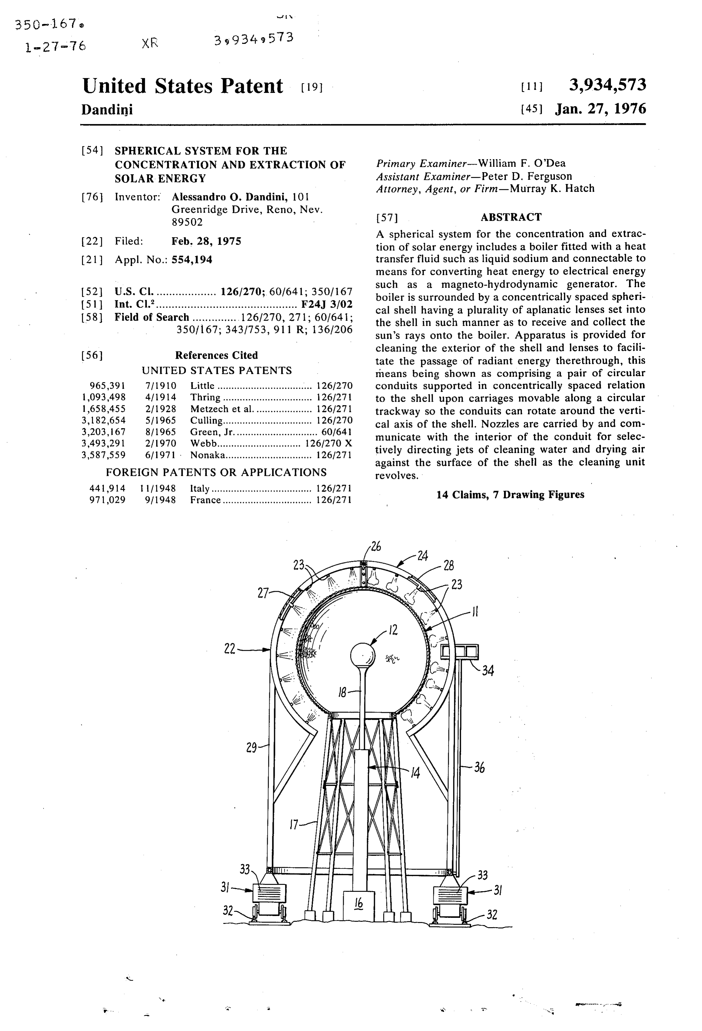
22 Filed: Feb. 28, 1975 A spherical system for the concentration and extrac tion of solar energy includes a boiler fitted with a heat (21) Appl. No.: 554,194 transfer fluid such as liquid sodium and connectable to means for converting heat energy to electrical energy such as a magneto-hydrodynamic generator. The 52 U.S. Cl. ................... 126/270; 60/641; 350/167 boiler is surrounded by a concentrically spaced spheri 15ll Int. Cl.............................................. F24J 3/02 cal shell having a plurality of aplanatic lenses set into 58) Field of Search............... 126/270, 271; 60/641; the shell in such manner as to receive and collect the 350/167; 3431753, 911 R; 1361206 sun's rays onto the boiler. Apparatus is provided for 56 References Cited cleaning the exterior of the shell and lenses to facili tate the passage of radiant energy therethrough, this
UNITED STATES PATENTS means being shown as comprising a pair of circular 965,391 7/1910 Little .................................. 1261270 conduits supported in concentrically spaced relation 1,093498 4/1914. Thring.............. ... 126/271 to the shell upon carriages movable along a circular 1,658,455 211928 Metzech et al... ... 126/271 trackway so the conduits can rotate around the verti 3, 182,654 5/1965 Culling.............. ... 126/270 cal axis of the shell. Nozzles are carried by and com 3,203, 167 8/1965 Green, Jr.............................. 60/641 municate with the interior of the conduit for selec 3,493,291 21 1970 Webb......... 126/270 X tively directing jets of cleaning water and drying air 3,587,559 6/1971 Nonaka............................... 126/271 against the surface of the shell as the cleaning unit
FOREIGN PATENTS OR APPLICATIONS revolves.
441,914 1/1948 Italy.................................... 1261271 14 Claims, 7 Drawing Figures 971,029 9/1948 France................................ 1261271
Page 2
Drawing sheet — no readable text.
Page 3
Drawing sheet — no readable text.
Page 4
Drawing sheet — no readable text.
Page 5
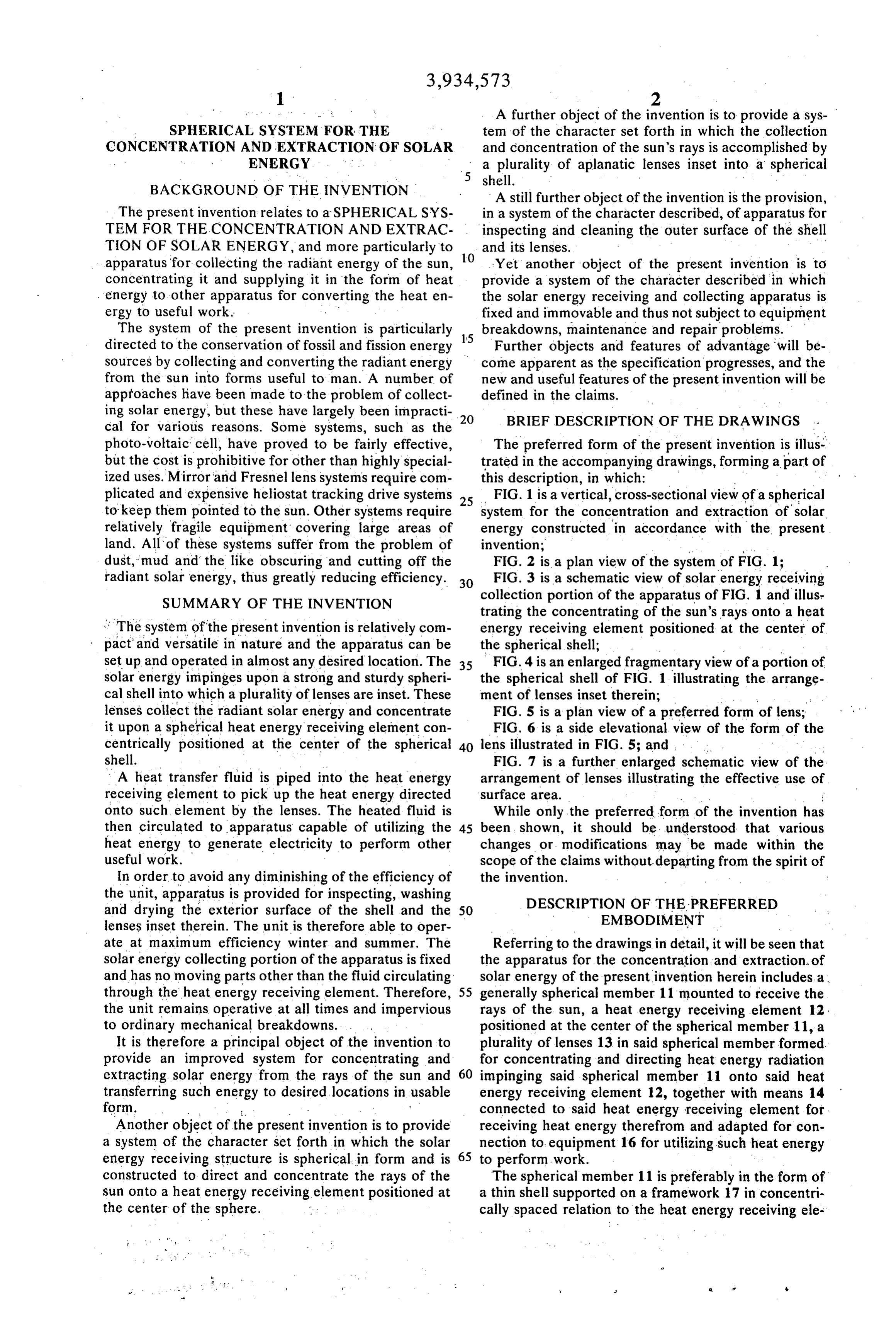
A further object of the invention is to provide a sys
SPHERICAL SYSTEM FOR THE tem of the character set forth in which the collection CONCENTRATION AND EXTRACTION OF SOLAR and concentration of the sun's rays is accomplished by ENERGY a plurality of aplanatic lenses inset into a spherical shell.
BACKGROUND OF THE INVENTION A still further object of the invention is the provision, The present invention relates to a SPHERICAL SYS in a system of the character described, of apparatus for TEM FOR THE CONCENTRATION AND EXTRAC inspecting and cleaning the outer surface of the shell TION OF SOLAR ENERGY, and more particularly to 10 and its lenses.
apparatus for collecting the radiant energy of the sun, Yet another object of the present invention is to concentrating it and supplying it in the form of heat provide a system of the character described in which energy to other apparatus for converting the heat en the solar energy receiving and collecting apparatus is ergy to useful work. fixed and immovable and thus not subject to equipment The system of the present invention is particularly 15 breakdowns, maintenance and repair problems. directed to the conservation of fossil and fission energy Further objects and features of advantage will be sources by collecting and converting the radiant energy come apparent as the specification progresses, and the from the sun into forms useful to man. A number of new and useful features of the present invention will be approaches have been made to the problem of collect defined in the claims.
ing solar energy, but these have largely been impracti 20 cal for various reasons. Some systems, such as the BRIEF DESCRIPTION OF THE DRAWINGS photo-voltaic cell, have proved to be fairly effective, The preferred form of the present invention is illus but the cost is prohibitive for other than highly special trated in the accompanying drawings, forming apart of ized uses. Mirror and Fresnel lens systems require com this description, in which:
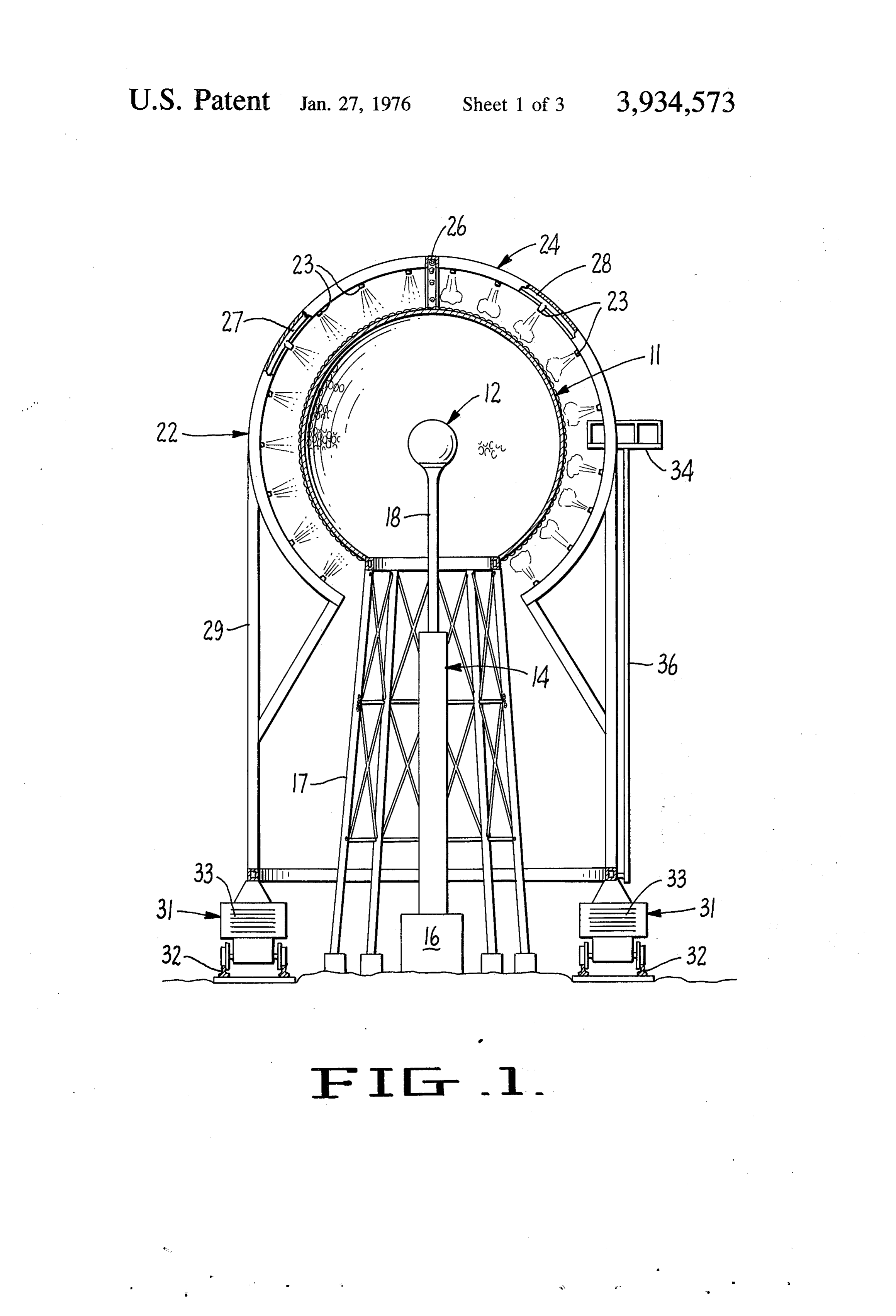
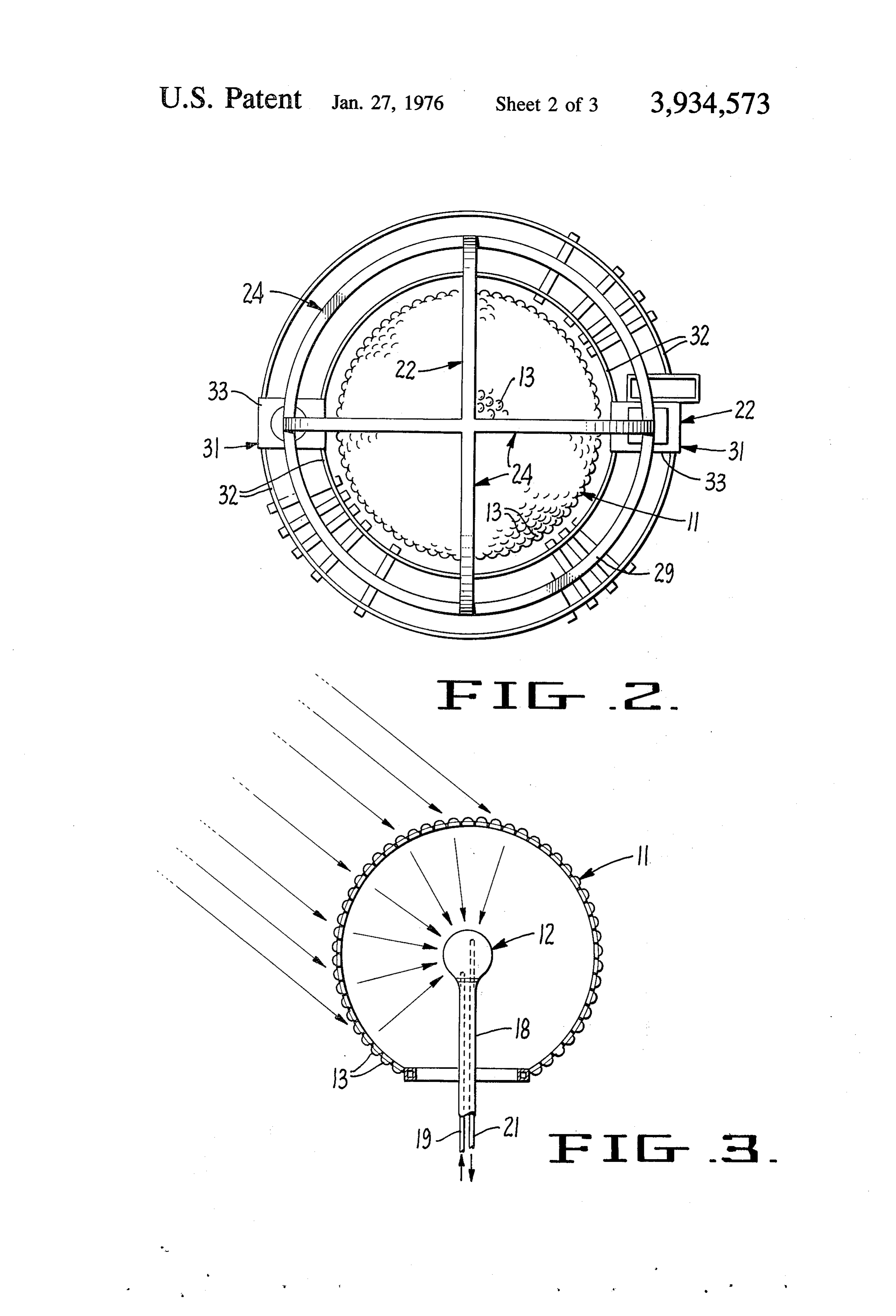
plicated and expensive heliostat tracking drive systems 25 FIG. 1 is a vertical, cross-sectional view of a spherical to keep them pointed to the sun. Other systems require system for the concentration and extraction of solar relatively fragile equipment covering large areas of energy constructed in accordance with the present land. All of these systems suffer from the problem of invention; . .. dust, mud and the like obscuring and cutting off the FIG. 2 is a plan view of the system of FIG. 1; radiant solar energy, thus greatly reducing efficiency. 30 FIG. 3 is a schematic view of solar energy receiving SUMMARY OF THE INVENTION collection portion of the apparatus of FIG. 1 and illus trating the concentrating of the sun's rays onto a heat * The system of the present invention is relatively com energy receiving element positioned at the center of pact and versatile in nature and the apparatus can be the spherical shell;
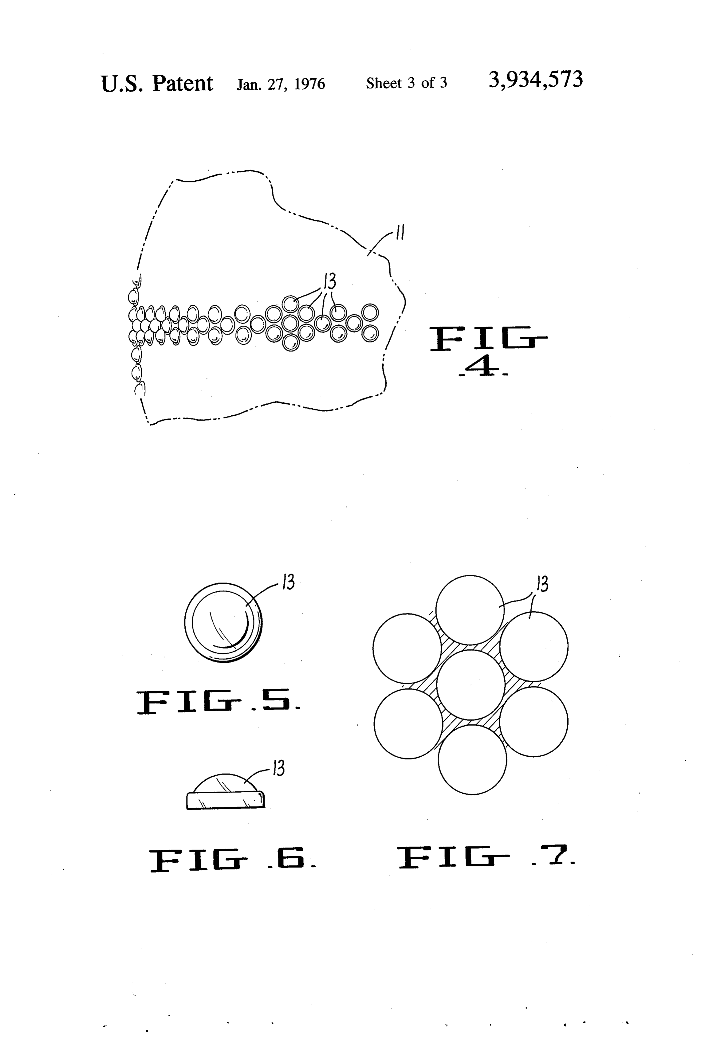
set up and operated in almost any desired location. The 35 FIG. 4 is an enlarged fragmentary view of a portion of solar energy impinges upon a strong and sturdy spheri the spherical shell of FIG. 1 illustrating the arrange cal shell into which a plurality of lenses are inset. These ment of lenses inset therein; lenses collect the radiant solar energy and concentrate FIG. 5 is a plan view of a preferred form of lens; it upon a spherical heat energy receiving element con FIG. 6 is a side elevational view of the form of the centrically positioned at the center of the spherical 40 lens illustrated in FIG. 5; and .. .. . . shell. FIG. 7 is a further enlarged schematic view of the A heat transfer fluid is piped into the heat energy arrangement of lenses illustrating the effective use of receiving element to pick up the heat energy directed surface area. ; onto such element by the lenses. The heated fluid is While only the preferred form of the invention has then circulated to apparatus capable of utilizing the 45 been shown, it should be understood that various heat energy to generate electricity to perform other changes or modifications may be made within the useful work. scope of the claims without departing from the spirit of In order to avoid any diminishing of the efficiency of the invention.
the unit, apparatus is provided for inspecting, washing and drying the exterior surface of the shell and the 50 DESCRIPTION OF THE PREFERRED lenses inset therein. The unit is therefore able to oper EMBODIMENT ate at maximum efficiency winter and summer. The Referring to the drawings in detail, it will be seen that solar energy collecting portion of the apparatus is fixed the apparatus for the concentration and extraction. of and has no moving parts other than the fluid circulating solar energy of the present invention herein includes a , through the heat energy receiving element. Therefore, 55 generally spherical member 11 mounted to receive the the unit remains operative at all times and impervious rays of the sun, a heat energy receiving element 12 to ordinary mechanical breakdowns. positioned at the center of the spherical member 11, a It is therefore a principal object of the invention to plurality of lenses 13 in said spherical member formed provide an improved system for concentrating and for concentrating and directing heat energy radiation extracting solar energy from the rays of the sun and 60 impinging said spherical member 11 onto said heat transferring such energy to desired locations in usable energy receiving element 12, together with means 14 form. - . connected to said heat energy receiving element for Another object of the present invention is to provide receiving heat energy therefrom and adapted for con a system of the character set forth in which the solar nection to equipment 16 for utilizing such heat energy energy receiving structure is spherical in form and is 65 to perform work.
constructed to direct and concentrate the rays of the The spherical member 11 is preferably in the form of sun onto a heat energy receiving element positioned at a thin shell supported on a framework 17 in concentri the center of the sphere. cally spaced relation to the heat energy receiving ele
Page 6
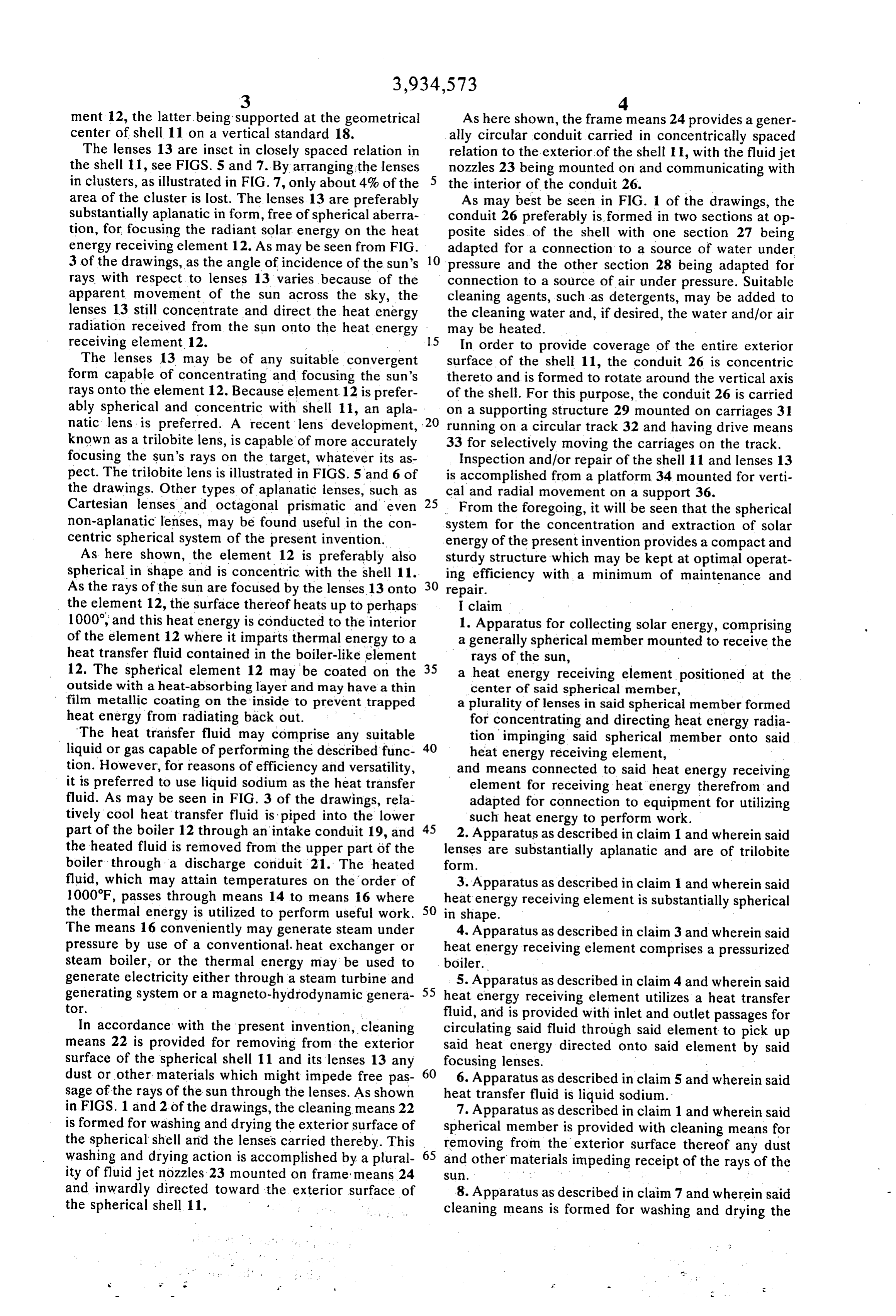
ment 12, the latter being supported at the geometrical As here shown, the frame means 24 provides a gener center of shell 11 on a vertical standard 18. ally circular conduit carried in concentrically spaced The lenses 13 are inset in closely spaced relation in relation to the exterior of the shell 11, with the fluid jet the shell 11, see FIGS. 5 and 7. By arranging the lenses nozzles 23 being mounted on and communicating with in clusters, as illustrated in FIG. 7, only about 4% of the the interior of the conduit 26. area of the cluster is lost. The lenses 13 are preferably As may best be seen in FIG. 1 of the drawings, the substantially aplanatic in form, free of spherical aberra conduit 26 preferably is formed in two sections at op tion, for focusing the radiant solar energy on the heat posite sides of the shell with one section 27 being energy receiving element 12. As may be seen from FIG. adapted for a connection to a source of water under 3 of the drawings, as the angle of incidence of the sun's 10 pressure and the other section 28 being adapted for rays with respect to lenses 13 varies because of the connection to a source of air under pressure. Suitable apparent movement of the sun across the sky, the cleaning agents, such as detergents, may be added to lenses 13 still concentrate and direct the heat energy the cleaning water and, if desired, the water and/or air radiation received from the sun onto the heat energy may be heated.
receiving element 12. . 15 In order to provide coverage of the entire exterior The lenses 13 may be of any suitable convergent surface of the shell 11, the conduit 26 is concentric form capable of concentrating and focusing the sun's thereto and is formed to rotate around the vertical axis rays onto the element 12. Because element 12 is prefer of the shell. For this purpose, the conduit 26 is carried ably spherical and concentric with shell 11, an apla on a supporting structure 29 mounted on carriages 31 natic lens is preferred. A recent lens development, 20 running on a circular track 32 and having drive means known as a trilobite lens, is capable of more accurately 33 for selectively moving the carriages on the track. focusing the sun's rays on the target, whatever its as Inspection and/or repair of the shell 11 and lenses 13 pect. The trilobite lens is illustrated in FIGS. 5 and 6 of is accomplished from a platform 34 mounted for verti the drawings. Other types of aplanatic lenses, such as cal and radial movement on a support 36. Cartesian lenses and octagonal prismatic and even 25 From the foregoing, it will be seen that the spherical non-aplanatic lenses, may be found useful in the con system for the concentration and extraction of solar centric spherical system of the present invention. energy of the present invention provides a compact and As here shown, the element 12 is preferably also sturdy structure which may be kept at optimal operat spherical in shape and is concentric with the shell 11. 30 ing efficiency with a minimum of maintenance and As the rays of the sun are focused by the lenses. 13 onto repair. - - -
the element 12, the surface thereof heats up to perhaps claim 1000, and this heat energy is conducted to the interior 1. Apparatus for collecting solar energy, comprising of the element 12 where it imparts thermal energy to a a generally spherical member mounted to receive the heat transfer fluid contained in the boiler-like element 35 rays of the sun, 12. The spherical element 12 may be coated on the a heat energy receiving element positioned at the outside with a heat-absorbing layer and may have a thin center of said spherical member, film metallic coating on the inside to prevent trapped a plurality of lenses in said spherical member formed heat energy from radiating back out. for concentrating and directing heat energy radia The heat transfer fluid may comprise any suitable tion impinging said spherical member onto said liquid or gas capable of performing the described func 40 heat energy receiving element, tion. However, for reasons of efficiency and versatility, and means connected to said heat energy receiving it is preferred to use liquid sodium as the heat transfer element for receiving heat energy therefrom and fluid. As may be seen in FIG. 3 of the drawings, rela adapted for connection to equipment for utilizing tively cool heat transfer fluid is piped into the lower 45 such heat energy to perform work. part of the boiler 12 through an intake conduit 19, and 2. Apparatus as described in claim 1 and wherein said the heated fluid is removed from the upper part of the lenses are substantially aplanatic and are of trilobite boiler through a discharge conduit 21. The heated form.
fluid, which may attain temperatures on the order of 3. Apparatus as described in claim 1 and wherein said 1000F, passes through means 14 to means 16 where heat energy receiving element is substantially spherical the thermal energy is utilized to perform useful work. 50 in shape.
The means 16 conveniently may generate steam under 4. Apparatus as described in claim 3 and wherein said pressure by use of a conventional. heat exchanger or heat energy receiving element comprises a pressurized steam boiler, or the thermal energy may be used to boiler.
generate electricity either through a steam turbine and 5. Apparatus as described in claim 4 and wherein said generating system or a magneto-hydrodynamic genera 55 heat energy receiving element utilizes a heat transfer tor. fluid, and is provided with inlet and outlet passages for In accordance with the present invention, cleaning circulating said fluid through said element to pick up means 22 is provided for removing from the exterior said heat energy directed onto said element by said surface of the spherical shell 11 and its lenses 13 any focusing lenses.
dust or other materials which might impede free pas 60 6. Apparatus as described in claim 5 and wherein said sage of the rays of the sun through the lenses. As shown heat transfer fluid is liquid sodium. in FIGS. 1 and 2 of the drawings, the cleaning means 22 7. Apparatus as described in claim 1 and wherein said is formed for washing and drying the exterior surface of spherical member is provided with cleaning means for the spherical shell and the lenses carried thereby. This washing and drying action is accomplished by a plural 65 removing from the exterior surface thereof any dust and other materials impeding receipt of the rays of the ity of fluid jet nozzles 23 mounted on frame means 24 Sl.
and inwardly directed toward the exterior surface of 8. Apparatus as described in claim 7 and wherein said the spherical shell 11. cleaning means is formed for washing and drying the
Page 7
S 6 exterior surface of said spherical member and the 11. Apparatus as described in claim 10 and wherein lenses thereon. said frame means provides a generally circular conduit 9. Apparatus for the concentration and extraction of carried in concentrically spaced relation to the exterior solar energy, comprising of said shell, and said fluid jets are provided by nozzles a generally spherical member having a supporting 5 mounted on and communicating with the interior of tower, said conduit.
a plurality of convergence lenses inset into said 12. Apparatus as described in claim 11 and wherein spherical member and formed for receiving and said conduit is formed in two sections at opposite sides focusing the rays of the sun onto an area at the 10 of said shell with one section adapted for connection to center of said spherical member, a source of water under pressure and the other section a spherical boiler having a supporting standard and adapted for connection to a source of air under pres
positioned in said area for receiving the focused 13. Apparatus as described in claim 11 and wherein rays of the sun from said lenses, said conduit is formed to rotate around the vertical axis frame means in spaced relation to the exterior of said 15 of said shell.
spherical member, 14. Apparatus as described in claim 12, and wherein and a plurality of fluid jets carried on said frame said conduit is formed to rotate around the vertical axis means and inwardly directed toward said spherical of said shell, said conduit is carried on a supporting member for effecting cleaning of said lenses. structure having carriages running on a circular track, 10. Apparatus as described in claim 9 and wherein and drive means is provided for selectively moving said said spherical member comprises a shell of generally carriages on said track.
spherical form and said lenses are inset into said shell. sk s: se ck sk
Provenance
- Collection
- Cited prior art
- Original PDF
- patentimages.storage.googleapis.com →
- Filed
- 1975-02-28
- Pages
- 7
- Method
- pdftotext (the PDF's own text layer) + pdftoppm 300dpi page scans
- Source
- Google Patents bibliographic record
- Granted
- 1976-01-27
- Inventors
- Alessandro O. Dandini
- Transcribed from
- patentimages.storage.googleapis.com →