patent · US3916338
Metal atom oxidation laser
28 October 1975
Page 1 — bibliographic record
United States Patent (19) (11) 3,916,338 Jensen et al. (45) *Oct. 28, 1975 54 METAL ATOM OXIDATION LASER 58 Field of Search...................... 331/94.5; 330/4.3 75 Inventors: Reed J. Jensen; Walter W. Rice;
Willard H. Beattie, all of Los 56) References Cited
Alamos, N. Mex. UNITED STATES PATENTS 73) Assignee: The United States of America as 3,701,045 10/1972 Bronfin et al.................. 33 1/94.5 G represented by the United States 3,829,793 8/1974 Jensen et al.................... 33 1/94.5 P Energy Research and Development
Administration, Washington, D.C. Primary Examiner-Robert J. Webster
Attorney, Agent, or Firm-Dean E. Carlson; Edward ( * Notice: The portion of the term of this C. Walterscheid patent subsequent to Aug. 13, 1991, has been disclaimed. (57) ABSTRACT 22) Filed: May 13, 1974 A chemical laser which operates by formation of metal or carbon atoms and reaction of such atoms (21) Appl. No.: 469,737 with a gaseous oxidizer in an optical resonant cavity. Related U.S. Application Data The lasing species are diatomic or polyatomic in na 63) Continuation-in-part of Ser. No. 304,578, Nov. 7, ture and are readily produced by exchange or other 1972. abstraction reactions between the metal or carbon atoms and the oxidizer. The lasing molecules may be 52 U.S. Cl.......... 331/94.5 G; 331/94.5 P; 330/4.3 metal or carbon monohalides or monoxides. (51) Int. Cl.’....................... H01S 3/22; H01S 3/095 17 Claims, 9 Drawing Figures
Page 2
Drawing sheet — no readable text.
Page 3
Drawing sheet — no readable text.
Page 4
Drawing sheet — no readable text.
Page 5
Drawing sheet — no readable text.
Page 6
Drawing sheet — no readable text.
Page 7
Drawing sheet — no readable text.
Page 8
METAL ATOM OXIDATION LASER (1965). To date, however, the literature reveals no op erative metal atom-oxidizer chemical laser system.
REFERENCE TO RELATED APPLICATIONS
SUMMARY OF THE INVENTION
This application is a continuation-in-part of applica tion Ser. No. 304,578, also entitled “Metal Atom Oxi We have found that by producing copious quantities dation Laser,' and filed Nov. 7, 1972. of metal or carbon atoms in a reaction vessel contain ing a gaseous oxidizer and placed within an optical res
BACKGROUND OF THE INVENTION onant cavity, chemical lasing may readily be achieved. The invention described herein was made in the The lasing species are molecular in nature and are course of, or under, a contract with the U.S. ATOMIC O readily produced by exchange or other abstraction re ENERGY COMMISSION. It relates to chemical lasers actions between the metal or carbon atoms and the oxi and more particularly to a chemical laser in which dizer. The molecular species may be metal or carbon atoms of metal or carbon react with a gaseous oxidizer halides or oxides. Metals and oxidizers which will form to produce a lasing species. lasing molecular species are limited only by the re A chemical laser may be defined as a device in which 5 quirements that (1) the particular reaction forming the the conversion of the internal energy change of a chem speciesdeposited be exothermic, and (2) the exothermicity be in the molecular species sufficiently and with ical reaction into specific excitation of a product spe cies leads to critical population inversion and laser ac avibrational distribution to produce a population inversion in the levels leading to optical gain in the system.
tion. An external energy source may be-and indeed 20 Any metal-oxidizer combination which meets these most frequently is-used to initiate the chemical reac constraints is within the purview of this invention. Vari tion. The critical feature of a chemical laser is that the ous metals may be atomized lasing action depends on the making and breaking of by any of the following techniques: within the reaction vessel chemical bonds. The specific excitation produced may (b) imploding film, (c) explosively(a)driven exploding wire, jets, (d) take the form of rotational, vibrational, or electronic 25 rapid decomposition of gaseous organometallics and/or excitation. metal azides, (e) laser evaporation. Carbon atoms may The great majority of chemical lasers known in the be obtained by electrically exploding a graphite smear. art depend on the production of a vibrational In one embodiment, carbon and various metals are rotational population inversion. The population inver atomized in an atmosphere of gaseous fluorine. In this sion is typically produced by exchange reactions of the 30 embodiment, the following lasing species have been type produced: AlF, MgF, LiF, TiF, AuF, PtF, NiF, UF, A -- BC -) AB* - C FeF, CuF, VF, ZnF, ZrF, MoF, AgF, TaF, WF, and CF. In another embodiment employing the use of gaseous where A, B, and C are atoms. For the lasing reaction oxygen, the lasing species TiO, VO, ZrO, MoC), TaO, to proceed most effectively and efficiently it is neces 35 WO, UO, and CO have been formed. In a third embodi sary that large quantities of atomic species A be pro ment, lasing results from exploding a Tiwire in NF oxi duced within, or introduced into, the reaction vessel in dizer gas. In a fourth embodiment, exploding a U wire a very short time. Some form of energy input is neces in chlorine gas produces the lasing species of UCl. sary to produce large quantities of the atomic species
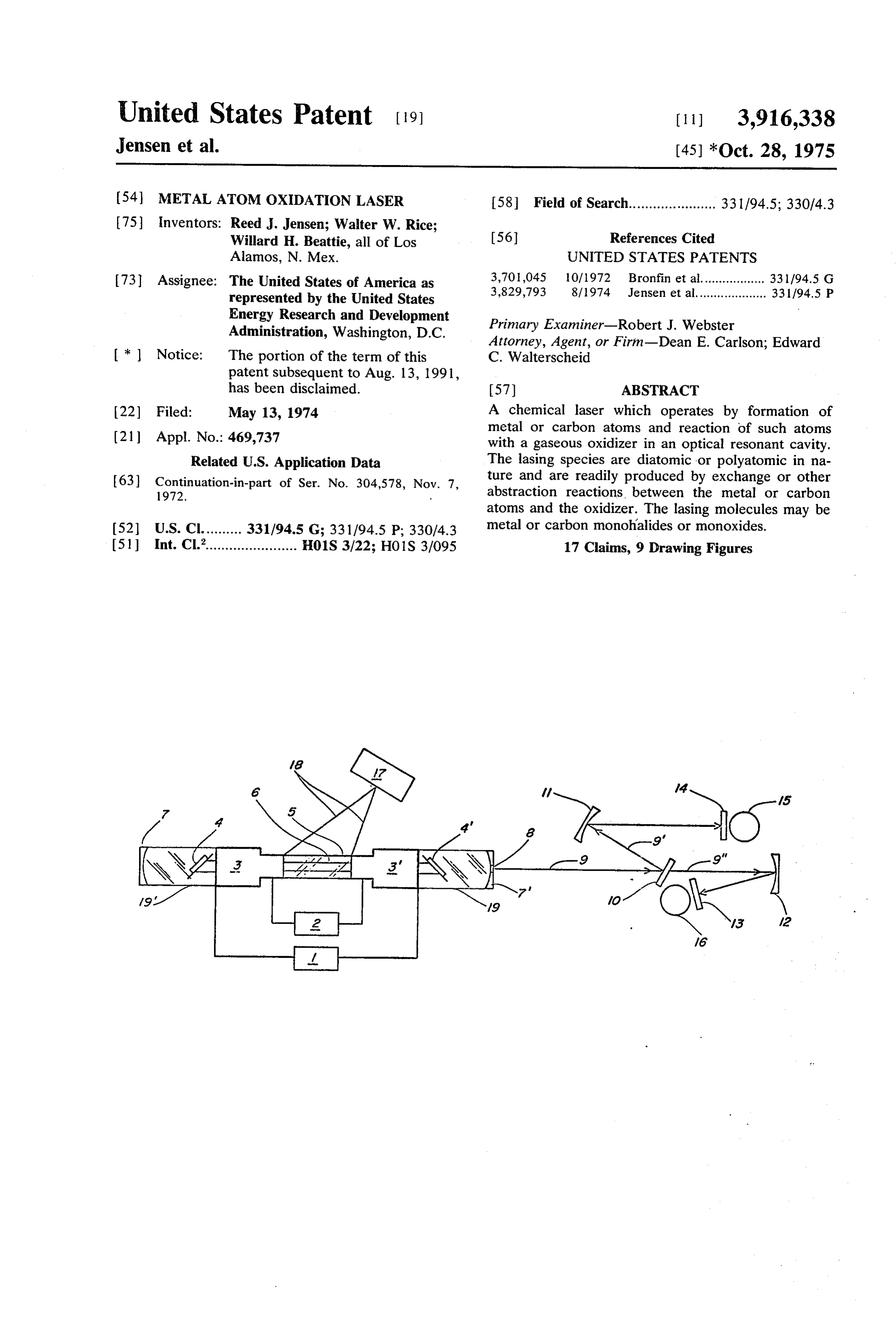
A. It is known in the art that this input energy may be 40 BRIEF DESCRIPTION OF THE DRAWINGS provided by means of light energy, electrical energy, FIG. 1 is a diagrammatic representation of the chemi chemical energy, or a combination of these. See, e.g., cal laser of this invention.
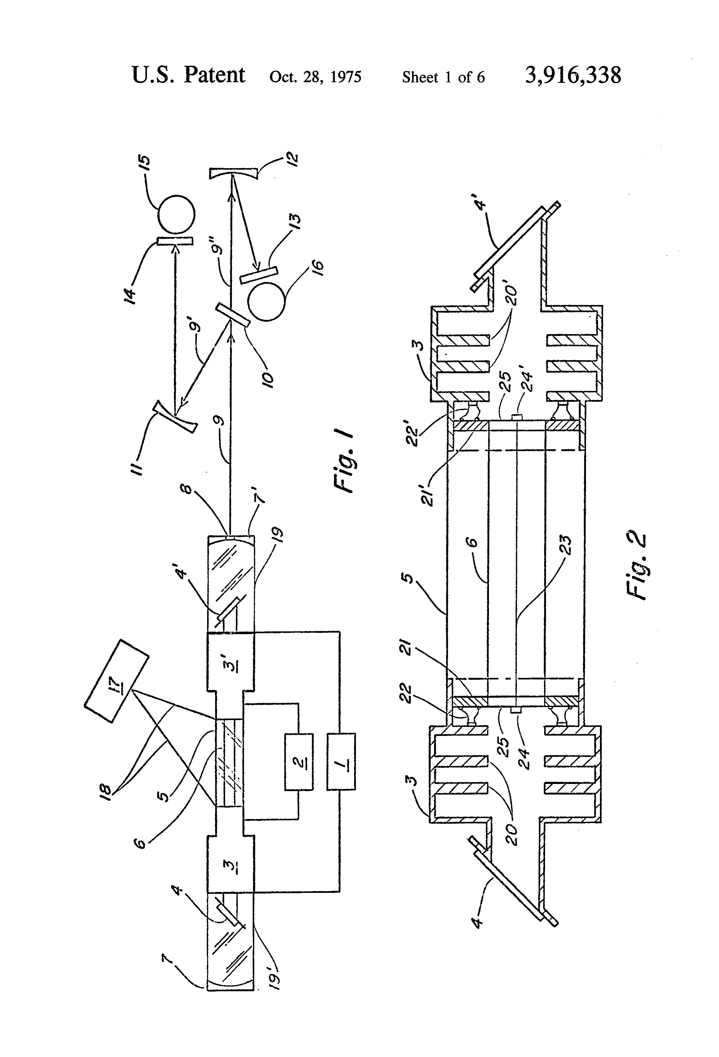
U.S. Pat. No. 3,662,280 for “Explosively Driven Pulsed FIG. 2 is a cross-sectional view of the reaction vessel Chemical Laser' issued to two of the present inventors, of FIG. 1 which shows exploding wire means for pro Jensen and Rice, on May 9, 1972. 45 ducing metal atoms.
Vibrationally excited diatomic or polyatomic species FIG. 3 is a cross-sectional view of the reaction vessel may also be readily prepared by abstraction reactions of FIG. 1 which shows imploding film means for pro of the type ducing metal atoms.
FIG. 4 is a cross-sectional view of the reaction vessel
of FIG. 1 which shows means for producing carbon where A, B, and C are atoms, atOS.
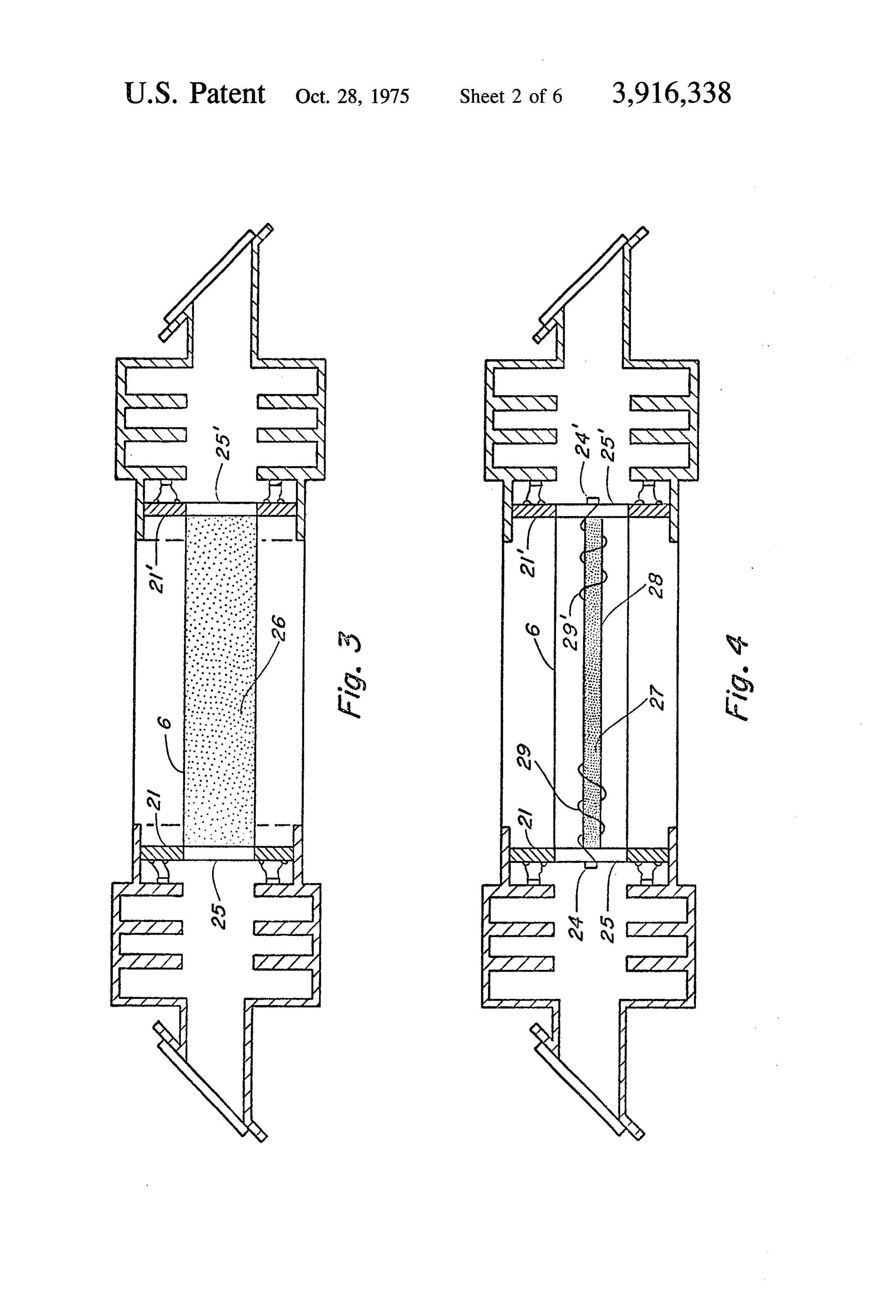
At the present time the only excited molecular spe FIG. 5 shows comparative oscillograms of visible flu cies known to lase as the result of formation from an orescence (VIS), infrared lasing (IR), voltage (E) at 15 exchange or abstraction reaction are HF, HCl, HBr, HI, 55 kV/div, and current (1) at 5 kA?div (except Li at 10 OH, and CO. The literature discloses, however, that kA/div) produced by exploding wires in oxidizing from the infancy of chemical lasers, the reactions of at gases. On visible fluorescence, negative deflection cor least certain metal atoms with an appropriate oxidizer responds to increasing intensity.
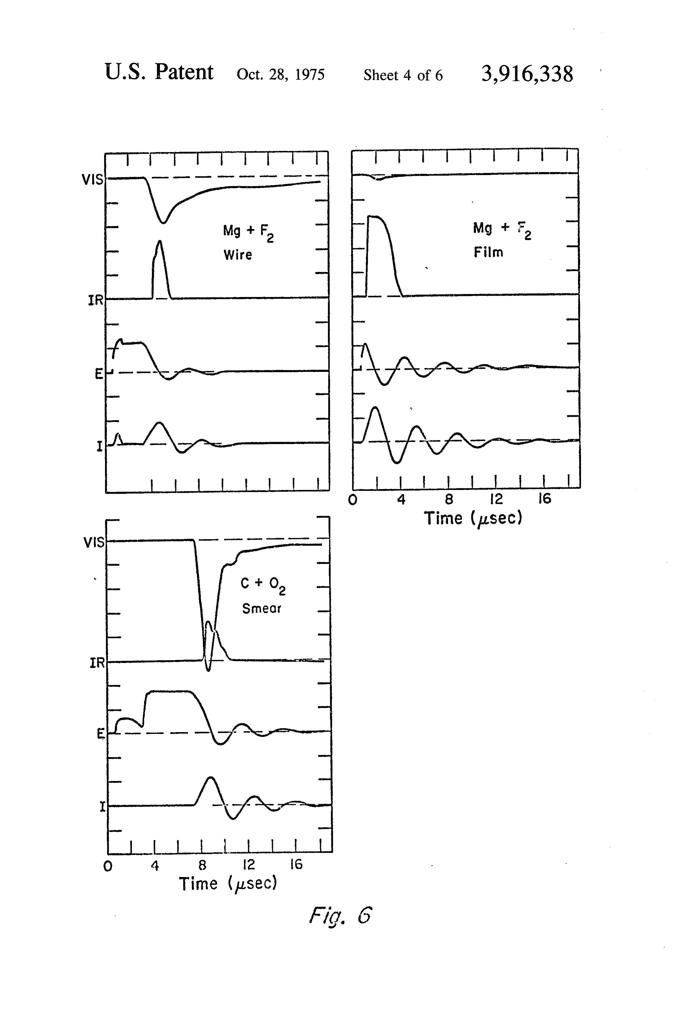
have theoretically been considered candidates for pro FIG. 6 shows comparative oscillograms of visible flu duction of lasing species in a chemical laser. Polanyi, 60 orescence (VIS), infrared lasing (IR), voltage (E) at 15 for example, proposed an alkali metal atom plus halo kV/div, and current (I) at 10 kA?div for three tech gen or halide as suitable reactions for producing vibra niques of atomization used in the apparatus of FIG. i. On visible fluorescence, negative deflection corre tional population inversion and hence lasing in a chem sponds ical laser. See, e.g., “Vibrational-Rotational Population to increasing intensity. FIG.
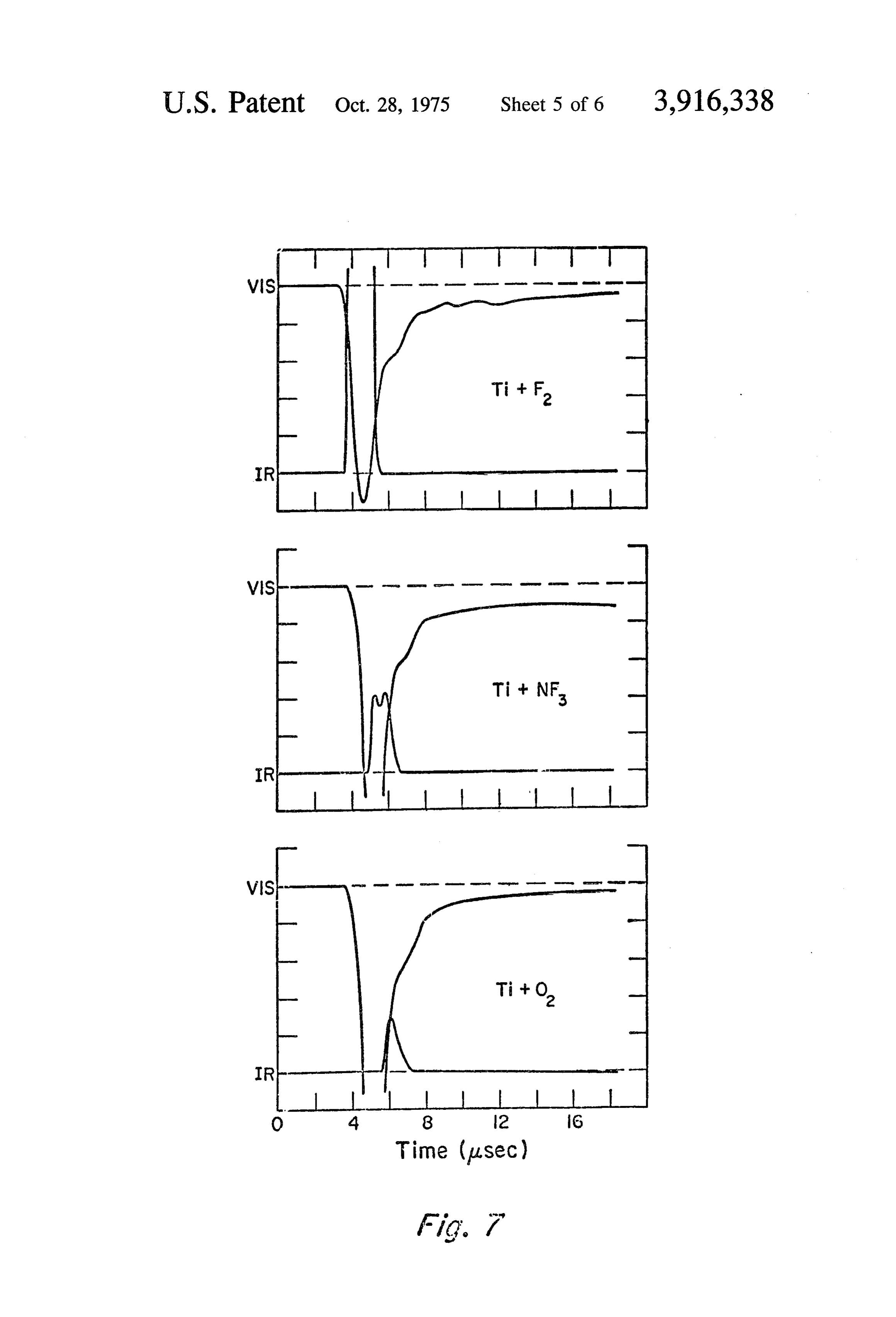
Inversion" presented at the Chemical Laser Confer 65 (VIS) and 7 shows oscillograms of visible fluorescence infrared lasing (IR) for an exploding Ti wire ence, University of California at San Diego, LaJolla, in three oxidizing gases. On visible fluorescence, nega California, September 9-11, 1964, and published in tive deflection corresponds
Applied Optics Supplement on Chemical Lasers, p. 109 to increasing intensity.
Page 9
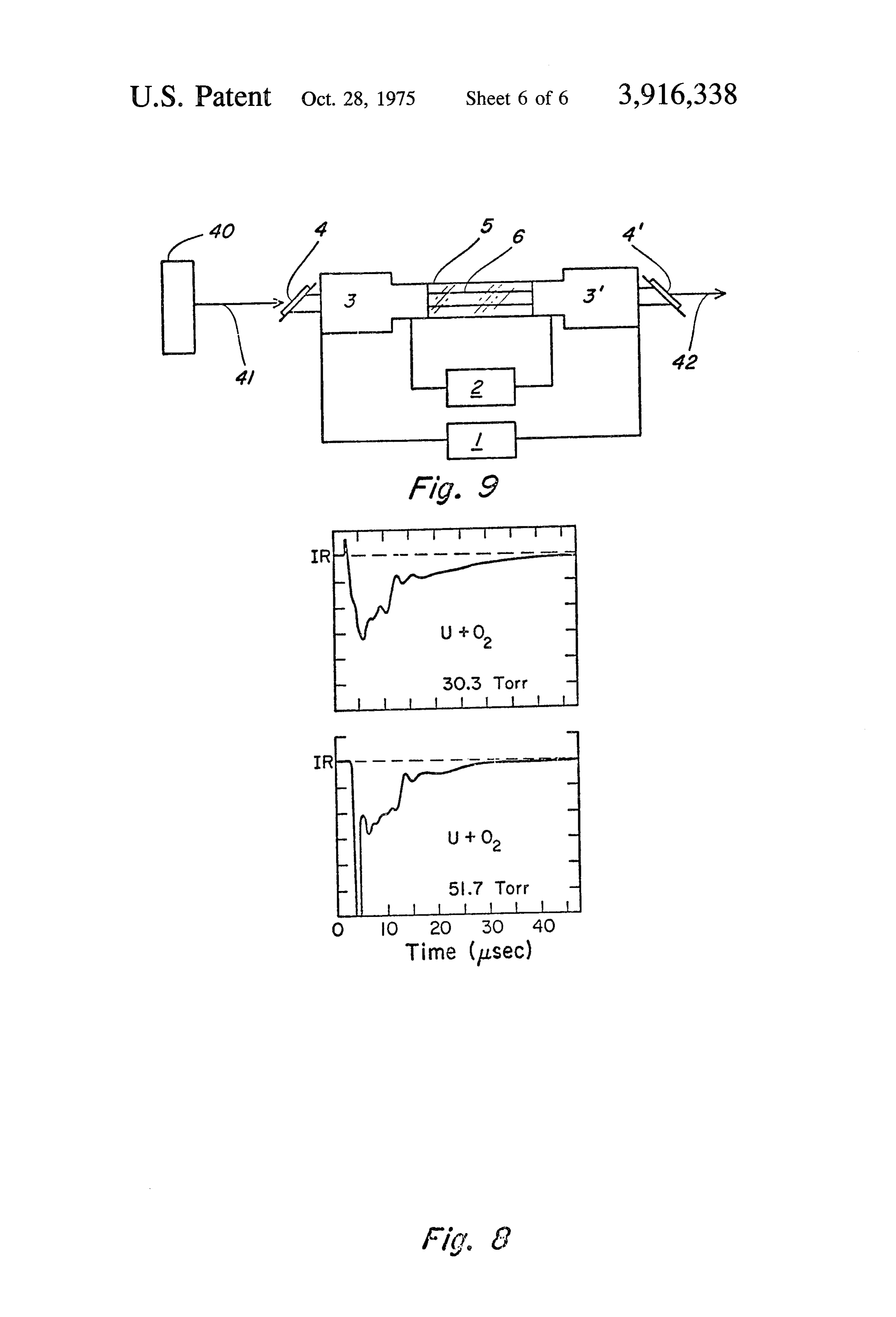
FIG. 8 is a comparison of oscillograms showing the 1 causes film 26 to implode, forming metal atoms in effect of oxidizer pressure on the laser threshold for U quantity which mix with the oxidizer in reaction vessel wire exploding into O. 6 and produce a lasing reaction and, thus, optical gain. FIG. 9 shows the laser of this invention in an ampli A means by which carbon atoms can be readily pro fier configuration. duced in reaction vessel 6 is shown in FIG. 4. A glass rod 28 having a roughened surface is coated with
DESCRIPTION OF THE PREFERRED graphite 27 and inserted into reaction vessel 6. The EMBODIMENT coating may be readily accomplished by rubbing the rod with a soft graphite. A good electrical connection
One embodiment of the chemical laser of this inven 10 is established between end plates 2121' and graphite tion is shown in FIGS. 1 and 2. An optical resonant cav 27 by means of wire leads 29,29". When sufficient cur ity is formed by mirrors 7,7'. Reaction vessel 6 contain rent from power supply 1 is passed through the result ing an appropriate gaseous oxidizer supplied from oxi ing circuit, graphite coating explodes from rod 28 and dizer supply 2 is aligned along the optical axis of the produces a lasing reaction with the oxidizer in vessel 6. cavity. At either end of reaction vessel 6 are housings Other means may also be used to produce the requi 3,3' containing baffles 20,20' which protect optical site metal or carbon atoms in the reaction vessel. For windows 4,4' from the explosive effects of the reaction example, organometallic compounds or metal azides in vessel 6. Housings 3,3' are mounted to reaction ves may be rapidly decomposed in the reaction vessel. sel 6 by means of end plates 2121' having aligned Such decomposition is easily brought about through openings 25,25' centered therein. Safety vessel 5 sur use of electrical or light energy. Further, for very large rounds reaction vessel 6. The purpose of vessel 5 is to systems, appropriate metal jets may be produced protect against atmospheric contamination by the oxi through detonation of a high explosive shaped charge dizer within reaction vessel 6 in the event that vessel 6 having a hollow conical liner of the desired metal. Such should fail during operation of the laser. Sleeves 19, 19" techniques are well known in the explosives art. See, are provided so that the portions of the optical resonant 25 e.g., Wescott et al., 77 J. Geophysical Res. 2982 cavity between windows 4,4' and mirrors 7,7' may be (1972). Finally, metal vapor plumes may be formed by purged with an appropriate gas if desired. For diagnos laser energy deposition.
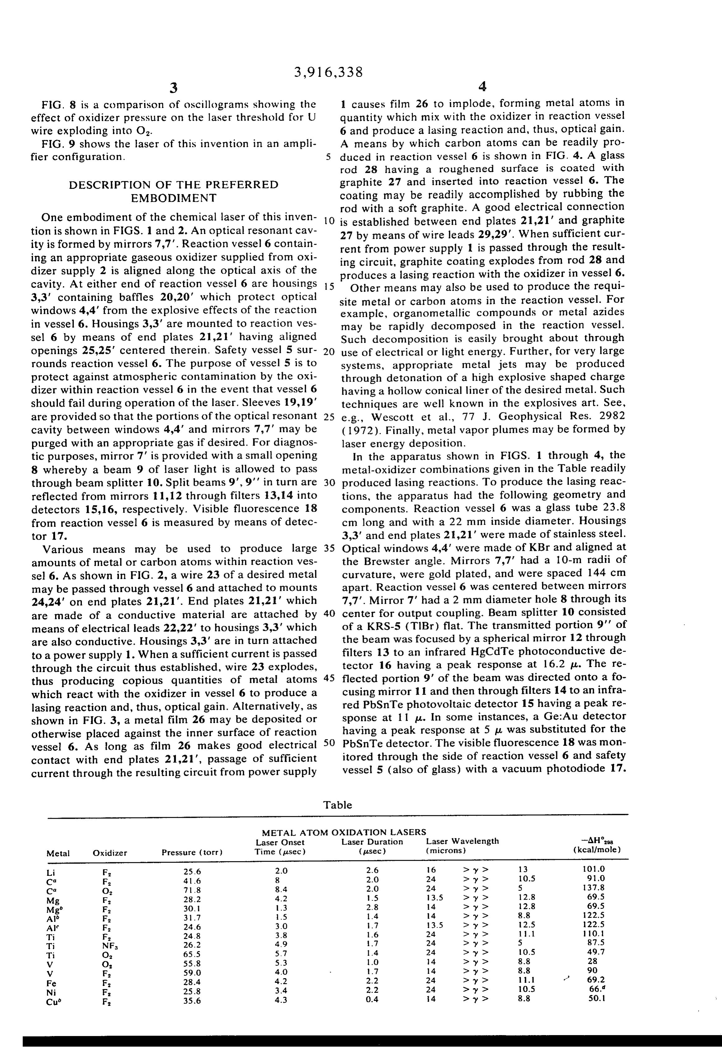
tic purposes, mirror 7' is provided with a small opening In the apparatus shown in FIGS. 1 through 4, the 8 whereby a beam 9 of laser light is allowed to pass metal-oxidizer combinations given in the Table readily through beam splitter 10. Split beams 9,9' in turn are 30 produced lasing reactions. To produce the lasing reac reflected from mirrors 11, 12 through filters 13, 14 into tions, the apparatus had the following geometry and detectors 15,16, respectively. Visible fluorescence 18 components. Reaction vessel 6 was a glass tube 23.8 from reaction vessel 6 is measured by means of detec cm long and with a 22 mm inside diameter. Housings tor 17. 3,3' and end plates 2,21' were made of stainless steel. Various means may be used to produce large 35 Optical windows 4,4' were made of KBr and aligned at amounts of metal or carbon atoms within reaction ves the Brewster angle. Mirrors 7,7' had a 10-m radii of sel 6. As shown in FIG. 2, a wire 23 of a desired metal curvature, were gold plated, and were spaced 144 cm may be passed through vessel 6 and attached to mounts apart. Reaction vessel 6 was centered between mirrors 24,24' on end plates 21,21". End plates 2121' which 7,7. Mirror 7' had a 2 mm diameter hole 8 through its are made of a conductive material are attached by 40 center for output coupling. Beam splitter 10 consisted means of electrical leads 22,22' to housings 3,3' which of a KRS-5 (TIBr) flat. The transmitted portion 9' of are also conductive. Housings 3,3' are in turn attached the beam was focused by a spherical mirror 12 through to a power supply 1. When a sufficient current is passed filters 13 to an infrared HgCdTe photoconductive de through the circuit thus established, wire 23 explodes, tector 16 having a peak response at 16.2 p. The re thus producing copious quantities of metal atoms 45 flected portion 9' of the beam was directed onto a fo which react with the oxidizer in vessel 6 to produce a cusing mirror 11 and then through filters 14 to an infra lasing reaction and, thus, optical gain. Alternatively, as red PbSnTe photovoltaic detector 15 having a peak re shown in FIG. 3, a metal film 26 may be deposited or sponse at 1 1 u. In some instances, a Ge:Au detector otherwise placed against the inner surface of reaction 50 having
PbSnTe a peak response at 5 p.u. was substituted for the detector. The visible fluorescence 18 was mon vessel 6. As long as film 26 makes good electrical contact with end plates 21,21", passage of sufficient itored through the side of reaction vessel 6 and safety current through the resulting circuit from power supply vessel 5 (also of glass) with a vacuum photodiode 17.
Table
METAL ATOM OXIDATION LASERS
Laser Onset Laser Duration Laser Wavelength -AH's
Metal Oxidizer Pressure (torr) Time (pl.sec.) (pl.sec.) (microns) (kcal/mole) Li F. 256 20 2.6 6 > y > 13 01.0 Ca F. 41-6 8 2.0 24 > y > 10.5 91.0 Ca O 718 8.4 20 24 > y > 5 37.8 Mg F. 28.2 4.2 5 3.5 > y > 12.8 69.5 Mg F. 30. 1.3 2.8 4. > y> 12.8 69.5 Ab F. 3.7 15 14 4 > y > 88 22.5 Af F. 24.6 3.0 7 3.5 > y > 2.5 22.5 Ti F. 24.8 38 1.6 24 > y > 1.1 O. Ti NF 26.2 49 7 24 > y > 5 87.5 Ti O 655 57 1.4 24 > y > 10.5 49.7 V O 55.8 5.3 1.0 14 > y > 8.8 28 V F. 59.0 4.O 7 14 > y > 8.8 90 Fe F. 28.4 4.2 22 24 > y > 1. 69.2 Ni F. 258 34 2.2 24 > y> 10.5 66. Cu F. 356 4.3 0.4 4. > y> 8.8 SO.
Page 10
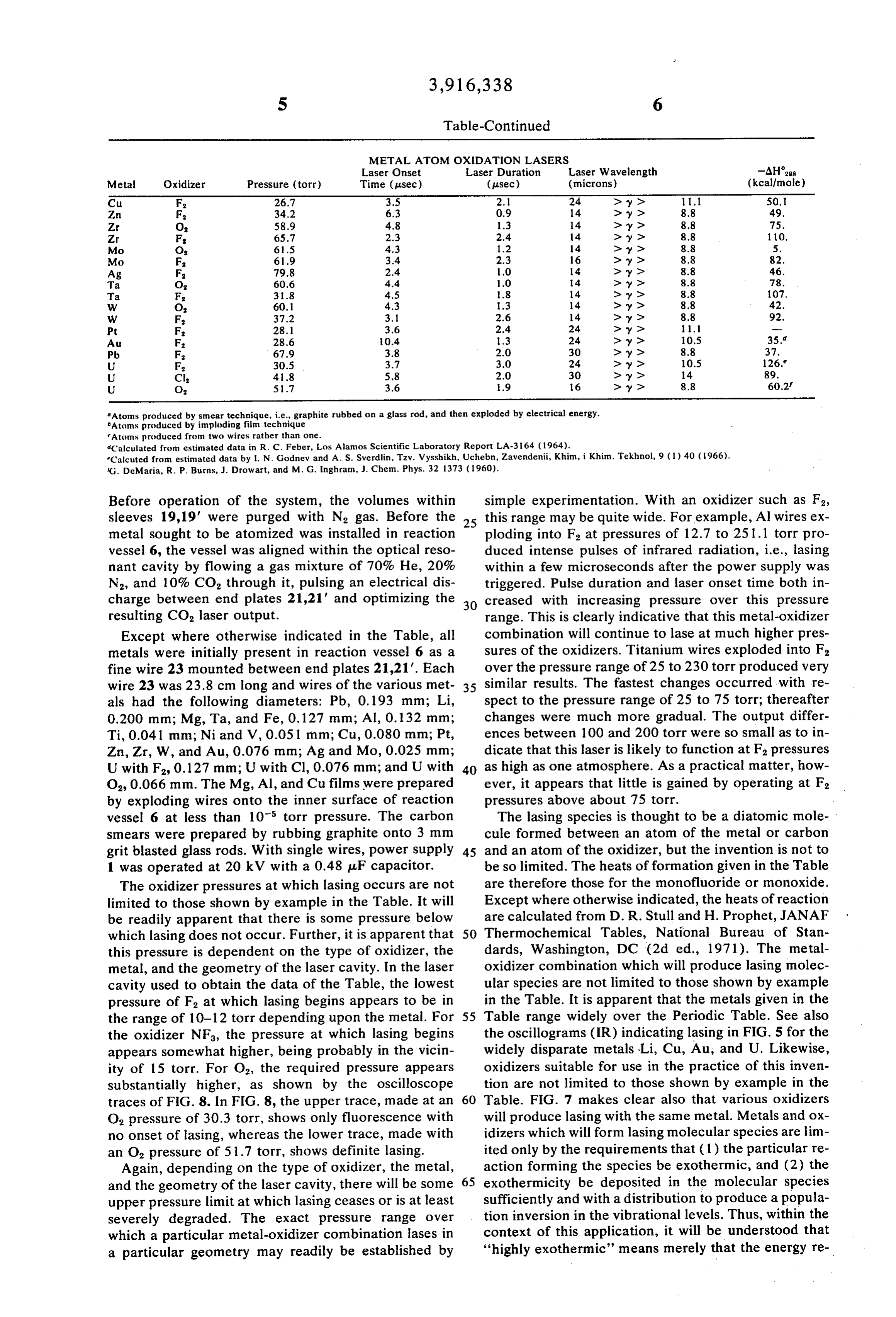
METAL ATOM OXDATION LASERS
Laser Onset Laser Duration Laser Wavelength -AHass
Metal Oxidizer Pressure (torr) Time (usec.) (pusec.) (microns) (kcal/mole) Cu F. 26.7 3.5 2. 24 > y> 11.1 50.1 Zn F. 34.2 6.3 0.9 14 > y> 8.8 49. Zr O 58.9 4.8 1.3 14 > y> 8.8 75. Zr F. 65.7 2.3 2.4 14 > y> 8.8 110. Mo O 61.5 4.3 1.2 14 > y> 8.8 5. Mo F. 61.9 3.4 2.3 16 > y> 8.8 82. Ag F. 79.8 2.4 1.0 14 > y> 8.8 46. Ta O 60.6 4.4 1.0 14 > y> 8.8 78. Ta F. 31.8 4.5 1.8 14 > y> 8.8 07. W O 60.1 4.3 1.3 14 > y> 8.8 42. W F. 37.2 3.1 2.6 14 > y> 8.8 92. Pt F. 28.1 3.6 2.4 24 > y > 1. - Au F. 28.6 0.4 1.3 24 > y> 10.5 35.d Pb F. 67.9 3.8 2.0 30 > y> 8.8 37. U F. 30.5 3.7 3.0 24 > y> 10.5 126. U Cl 4.1.8 5.8 2.0 30 > y > 14 89. U Oz 51.7 3.6 1.9 16 > y> 8.8 60.2
Atoms produced by smcar technique, i.e., graphite rubbed on a glass rod, and then exploded by electrical energy.
Atoms produced by imploding film technique
Atoms produced from two wires rather than one.
dCalculated from estimated data in R. C. Feber, Los Alamos Scientific Laboratory Report LA-364 (1964).
Calcuted from estimated data by I. N. Godnev and A. S. Sverdlin, Tzv. Vysshikh, Uchebin, Zavendenii, Khim, i Khim. Tekhnol, 9 (1) 40 (1966). (G. deMaria, R. P. Burns, J. Drowart, and M. G. Inghram, J. Chem. Phys. 32 1373 (1960).
Before operation of the system, the volumes within simple experimentation. With an oxidizer such as F, sleeves 19, 19' were purged with N, gas. Before the 25 this range may be quite wide. For example, Al wires ex metal sought to be atomized was installed in reaction ploding into F at pressures of 12.7 to 251.1 torr pro vessel 6, the vessel was aligned within the optical reso duced intense pulses of infrared radiation, i.e., lasing nant cavity by flowing a gas mixture of 70% He, 20% within a few microseconds after the power supply was
N2, and 10% CO, through it, pulsing an electrical dis triggered. Pulse duration and laser onset time both in charge between end plates 21,21' and optimizing the 30 creased with increasing pressure over this pressure resulting CO, laser output. range. This is clearly indicative that this metal-oxidizer
Except where otherwise indicated in the Table, all combination will continue to lase at much higher pres metals were initially present in reaction vessel 6 as a sures of the oxidizers. Titanium wires exploded into F, fine wire 23 mounted between end plates 21,21'. Each over the pressure range of 25 to 230 torr produced very wire 23 was 23.8 cm long and wires of the various met 35 similar results. The fastest changes occurred with re als had the following diameters: Pb, 0.193 mm; Li, spect to the pressure range of 25 to 75 torr; thereafter 0.200 mm; Mg, Ta, and Fe, 0.127 mm; Al, 0.132 mm; changes were much more gradual. The output differ Ti, 0.04.1 mm; Ni and V, 0.05.1 mm; Cu, 0.080 mm; Pt, ences between 100 and 200 torr were so small as to in Zn, Zr, W, and Au, 0.076 mm; Ag and Mo, 0.025 mm; dicate that this laser is likely to function at F. pressures
U with F, 0.127 mm; U with Cl, 0.076 mm; and U with 40 as high as one atmosphere. As a practical matter, how
O, 0.066 mm. The Mg, Al, and Cu films were prepared ever, it appears that little is gained by operating at F.
by exploding wires onto the inner surface of reaction pressures above about 75 torr.
vessel 6 at less than 10 torr pressure. The carbon The lasing species is thought to be a diatomic mole smears were prepared by rubbing graphite onto 3 mm cule formed between an atom of the metal or carbon grit blasted glass rods. With single wires, power supply 45 and an atom of the oxidizer, but the invention is not to 1 was operated at 20 kV with a 0.48 uF capacitor. be so limited. The heats of formation given in the Table
The oxidizer pressures at which lasing occurs are not are therefore those for the monofluoride or monoxide.
limited to those shown by example in the Table. It will Except where otherwise indicated, the heats of reaction be readily apparent that there is some pressure below are calculated from D. R. Stull and H. Prophet, JANAF which lasing does not occur. Further, it is apparent that 50 Thermochemical Tables, National Bureau of Stan this pressure is dependent on the type of oxidizer, the dards, Washington, DC (2d ed., 1971). The metal metal, and the geometry of the laser cavity. In the laser oxidizer combination which will produce lasing molec cavity used to obtain the data of the Table, the lowest ular species are not limited to those shown by example pressure of F, at which lasing begins appears to be in in the Table. It is apparent that the metals given in the the range of 10-12 torr depending upon the metal. For 55 Table range widely over the Periodic Table. See also the oxidizer NF, the pressure at which lasing begins the oscillograms (IR) indicating lasing in FIG. 5 for the appears somewhat higher, being probably in the vicin widely disparate metals Li, Cu, Au, and U. Likewise, ity of 15 torr. For O, the required pressure appears oxidizers suitable for use in the practice of this inven substantially higher, as shown by the oscilloscope tion are not limited to those shown by example in the traces of FIG. 8. In FIG. 8, the upper trace, made at an 60 Table. FIG. 7 makes clear also that various oxidizers
O, pressure of 30.3 torr, shows only fluorescence with will produce lasing with the same metal. Metals and ox no onset of lasing, whereas the lower trace, made with idizers which will form lasing molecular species are lim an O, pressure of 51.7 torr, shows definite lasing. ited only by the requirements that (1) the particular re
Again, depending on the type of oxidizer, the metal, action forming the species be exothermic, and (2) the and the geometry of the laser cavity, there will be some 65 exothermicity be deposited in the molecular species upper pressure limit at which lasing ceases or is at least sufficiently and with a distribution to produce a popula severely degraded. The exact pressure range over tion inversion in the vibrational levels. Thus, within the which a particular metal-oxidizer combination lases in context of this application, it will be understood that a particular geometry may readily be established by "highly exothermic" means merely that the energy re
Page 11
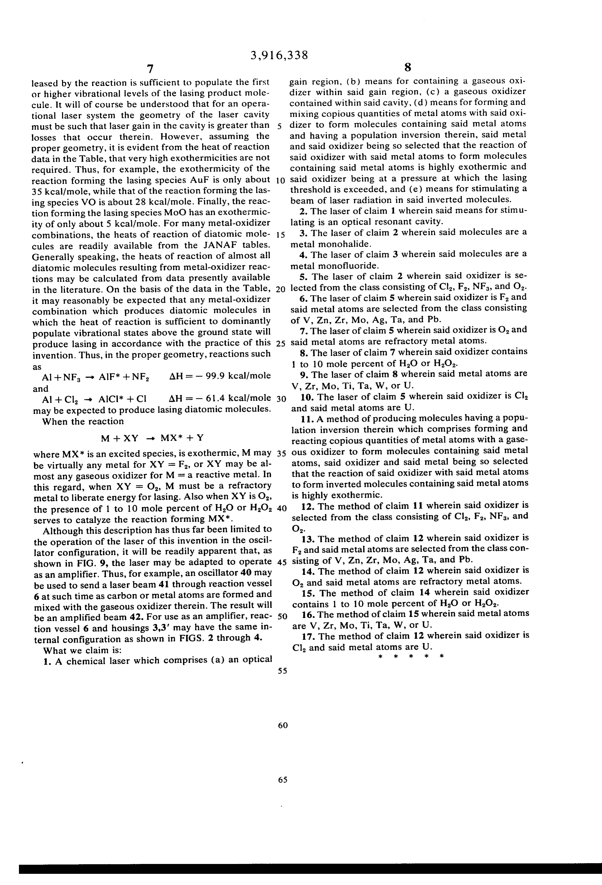
leased by the reaction is sufficient to populate the first gain region, (b) means for containing a gaseous oxi or higher vibrational levels of the lasing product mole dizer within said gain region, (c) a gaseous oxidizer cule. It will of course be understood that for an opera contained within said cavity, (d) means for forming and tional laser system the geometry of the laser cavity mixing copious quantities of metal atoms with said oxi must be such that laser gain in the cavity is greater than dizer to form molecules containing said metal atoms losses that occur therein. However, assuming the and having a population inversion therein, said metal proper geometry, it is evident from the heat of reaction and said oxidizer being so selected that the reaction of data in the Table, that very high exothermicities are not said oxidizer with said metal atoms to form molecules required. Thus, for example, the exothermicity of the containing said metal atoms is highly exothermic and reaction forming the lasing species AuF is only about 10 said oxidizer being at a pressure at which the lasing 35 kcal/mole, while that of the reaction forming the las threshold is exceeded, and (e) means for stimulating a ing species VO is about 28 kcal/mole. Finally, the reac beam of laser radiation in said inverted molecules. tion forming the lasing species MoC) has an exothermic 2. The laser of claim 1 wherein said means for stimu ity of only about 5 kcal/mole. For many metal-oxidizer lating is an optical resonant cavity. combinations, the heats of reaction of diatomic mole 15 3. The laser of claim 2 wherein said molecules are a cules are readily available from the JANAF tables. metal monohalide.
Generally speaking, the heats of reaction of almost all 4. The laser of claim 3 wherein said molecules are a diatomic molecules resulting from metal-oxidizer reac metal monofluoride.
tions may be calculated from data presently available 5. The laser of claim 2 wherein said oxidizer is se in the literature. On the basis of the data in the Table, 20 lected from the class consisting of Cl2, F, NF, and O. it may reasonably be expected that any metal-oxidizer 6. The laser of claim 5 wherein said oxidizer is F and combination which produces diatomic molecules in said metal atoms are selected from the class consisting which the heat of reaction is sufficient to dominantly of V, Zn, Zr, Mo, Ag, Ta, and Pb. populate vibrational states above the ground state will 7. The laser of claim 5 wherein said oxidizer is O and produce lasing in accordance with the practice of this 25 said metal atoms are refractory metal atoms. invention. Thus, in the proper geometry, reactions such 8. The laser of claim 7 wherein said oxidizer contains 3S 1 to 10 mole percent of H2O or H2O2. Al-NF - AlF* --NF, AH = - 99.9 kcal/mole 9. The laser of claim 8 wherein said metal atoms are and V, Zr, Mo, Ti, Ta, W, or U.
Al + Cl - AlCl* + Cl AH = - 61.4 kcal/mole 30 10. The laser of claim 5 wherein said oxidizer is Cl may be expected to produce lasing diatomic molecules. and said metal atoms are U.
When the reaction 11. A method of producing molecules having a popu lation inversion therein which comprises forming and
M -- XY - MX* -- Y reacting copious quantities of metal atoms with a gase where MX* is an excited species, is exothermic, M may 35 ous oxidizer to form molecules containing said metal be virtually any metal for XY = F, or XY may be al that atoms, said oxidizer and said metal being so selected most any gaseous oxidizer for M = a reactive metal. In the reaction of said oxidizer with said metal atons this regard, when XY = O, M must be a refractory to form inverted molecules containing said metal atoms metal to liberate energy for lasing. Also when XY is O, is highly exothermic.
the presence of 1 to 10 mole percent of HO or HO, 40 12. The method of claim 11 wherein said oxidizer is serves to catalyze the reaction forming MX*. selected from the class consisting of Cl2, F2, NFs, and Although this description has thus far been limited to O2.13. The method of claim 12 wherein said oxidizer is the operation of the laser of this invention in the oscil lator configuration, it will be readily apparent that, as F and said metal atoms are selected from the class con shown in FIG. 9, the laser may be adapted to operate 45 sisting of V, Zn, Zr, Mo, Ag, Ta, and Pb. as an amplifier. Thus, for example, an oscillator 40 may 14. The method of claim 12 wherein said oxidizer is be used to send a laser beam 41 through reaction vessel O and said metal atoms are refractory metal atoms. 6 at such time as carbon or metal atoms are formed and 15. The method of claim 14 wherein said oxidizer mixed with the gaseous oxidizer therein. The result will contains 1 to 10 mole percent of HO or H2O2. be an amplified beam 42. For use as an amplifier, reac 50 16. The method of claim 15 wherein said metal atoms tion vessel 6 and housings 3,3' may have the same in are V, Zr, Mo, Ti, Ta, W, or U.
ternal configuration as shown in FIGS. 2 through 4. 17. The method of claim 12 wherein said oxidizer is What we claim is: Cl and said metal atoms
are
1. A chemical laser which comprises (a) an optical
Provenance
- Collection
- Cited prior art
- Original PDF
- patentimages.storage.googleapis.com →
- Filed
- 1974-05-13
- Pages
- 11
- Method
- pdftotext (the PDF's own text layer) + pdftoppm 300dpi page scans
- Source
- Google Patents bibliographic record
- Granted
- 1975-10-28
- Inventors
- Reed J Jensen; Walter W Rice; Willard H Beattie; US Department of Energy
- Transcribed from
- patentimages.storage.googleapis.com →