patent · US6011192
Membrane-based conditioning for adsorption system feed gases
4 January 2000
Page 1 — bibliographic record
United States Patent (19) 11 Patent Number: 6,011, 192 Baker et al. (45) Date of Patent: Jan. 4, 2000
54 MEMBRANE-BASED CONDITIONING FOR 5,199,962 4/1993 Wijmans ..................................... 55/16 ADSORPTION SYSTEM FEED GASES 5,281.255 1/1994 Toy et al. . ... 95/50 5,332,424 7/1994 Rao et al. ................................... 95/47 75 Inventors: Richard W. Baker, Palo Alto; Kaaeid is: 6.0- Mars st al. .......................... 2- - -2 aOCl al. . . . . . . . . . . . . . . . . . . . . . . . . . . . . . . .
Alkhandwala, Union City, both of 5,374,300 12/1994 Kaschemekat et al. .................... 95/39 5,407,466 4/1995 Lokhandwala et al. .... ... 95/49 73 Assignee: Membrane Technology and Research, S.S. : hyl et also E. Inc., Menlo Park, Calif. 5,452.581 9/1995 Dinh et al. .................................. 62/24 5,457.256 10/1995 Mitariten et al. 585/655 21 Appl. No.: 09/083,560 5,501,722 3/1996 Toy et al. .................................... 95/50 5,507,856 4/1996 Rao et al. ................................... 95/50 22 Filed: May 22, 1998 5,634,354 6/1997 Howard et al. . ... 62/624 7 5,675,052 10/1997 Menon et al. .. 585/717 51 Int. Cl. .............................. C07C 7/00; CO7C 7/144 5,755,855 5/1998 Baker et al. ................................ 95/39 52 U.S. Cl. .......................... 585/818; 585/802; 585/803; 5,785,739 7/1998 Baker .......................................... 95/39
58 Field of Search ..................................... 585/802, 809, OTHER PUBLICATIONS 585/818, 819, 820, 822, 803 W.A. Bollinger et al., “Prism TM Separators Optimize Hydro cracker Hydrogen,” presented at AlChE 1983 Summer 56) References Cited National Meeting, Session No. 66, Aug. 29, 1983.
gen, Hydrocarbon Processing, Feb. 1995.
J.M.s Abrardo et al.,ss“Hydrogen Technologies to Meet Refin 3,567,632 3/1971 Richter et al. ............................ 210/23 ers Future Needs.” Hydrocarbon Processing, Feb. 1995. 4,229,188 10/1980 Intille .......................................... 55/16 H. Yamashiro et al., “Hydrogen Purification with Cellulose 4,230,463 10/1980 Henis et al. ... 55/16 Acetate Membranes, presented at Europe-Japan CongreSS 4,238.204 12/1980 Perry ............. ... 55/16 on Membranes and Membrane Processes, Jun. 18-21, 1984. 4,362,613 12/1982 MacLean .. ... 208/108 4,367,135 1/1983 Posey, Jr. ................................ 208/108 (List continued on next page.) 4,548,619 10/1985 Steacy ......................................... 55/16 4,654,063 3/1987 Auvil et al. ... 62/18 Primary Examiner Walter D. Griffin 4,690,695 9/1987 Doshi ............ ... 55/16 Assistant Examiner Tam M. Nguyen 4,701,187 10/1987 Choe et al. ... 55/16 Attorney, Agent, Or Firm-J. Farrant 4,783.203 11/1988 Doshi ............ ... 55/16 4,836,833 6/1989 Nicholas et al. ... 55/16 57 ABSTRACT 4,857,078 8/1989 Watler ............... ... 55/16 4,857,080 8/1989 Baker et al. .. ... 55/16 A process for treating gas Streams containing hydrogen and 4,863,492 9/1989 Doshi et al. .. ... 55/16 hydrocarbons. The process includes a membrane condition 4,892,564 1/1990 Cooley ...... ... 55/16 ing Step to remove C-C hydrocarbons, followed by a 4,963,165. 10/1990 Blume et al. . ... 55/16 Selective adsorption or membrane Separation Step to Separate 5,032,148 7/1991 Baker et al. . ... 55/16 hydrogen from methane. The membrane conditioning Step 5,053,067 10/1991 Chretien ........ ... 62/24 uses a membrane Selective for C-C hydrocarbons over 5,082,481 1/1992 Barchas et al. ... 62/23 hydrogen 5,089,033 2/1992 Wijmans ... ... 55/16 5,104,425 4/1992 Rao et al. ......... ... 55/16 5,157,200 10/1992 Mikkinen et al. ...................... 585/803 45 Claims, 5 Drawing Sheets
Page 2
OTHER PUBLICATIONS M. Anand et al., “Novel Selective Surface Flow (SSFTM) Membranes for the Recovery of Hydrogen from Waste Gas
H. Yamashiro et al., “Plant Uses Membrane Separation,” Streams,” Report by Air Products to DOE, Apr. 1996. Hydrocarbon Processing, Feb. 1985. T. Naheri et al., “Scale-Up of Selective Surface Flow “Polymeric Gas Separation Membranes,” Paul and Yampol Membrane for Gas Separation,” by Air Products and Chemi ski (eds.). (no date available). cals, Inc. (No date available). “Membrane Technology for Hydrocarbon Separation,” M. Anand “Novel Selective Surface Flow (SSFTM) Mem Membrane Associates Ltd. (no date available). branes for the Recovery of Hydrogen from Waste Gas E.W. Funk et al., “Effect of Impurities on Cellulose Acetate Streams,” by Air Products Inc., Report to DOE, Aug. 1995. Membrane Performance,” AlChE Symposium Series, No. M. Rao et al., “Practical Application of SSFTM Membrane,” 250, vol. 82. (no date available). Journal of Membrane Science 85 253–264, 1993. N.N. Li, et al. “Membrane Separation Processes in the M. Rao et al., “Nanoporous Carbon Membrane for Gas Petrochemical Industry,” Report by Allied-Signal Engi Separation,” Gas Separation and Purification, vol. 7, No. 4, neered Materials Research Center to DOE, Sep. 30, 1997. 1993.
Page 3
Drawing sheet — no readable text.
Page 4
Drawing sheet — no readable text.
Page 5
Drawing sheet — no readable text.
Page 6
Drawing sheet — no readable text.
Page 7
Drawing sheet — no readable text.
Page 8
MEMBRANE-BASED CONDITIONING FOR Zene production. U.S. Pat. No. 5,053,067, to L'Air Liquide, ADSORPTION SYSTEM FEED GASES discloses removal of part of the hydrogen from a refinery off-gas to facilitate downstream treatment. U.S. Pat. No.
FIELD OF THE INVENTION 5,082,481, to Lummus Crest, describes use of a membrane The invention relates to treatment of gas Streams contain for removal of hydrogen from cracking effluent. U.S. Pat. ing hydrogen and hydrocarbons. Specifically, the invention No. 5,157,200, to Institute Francais du Petrole, shows treat ment of light ends containing hydrogen and light hydrocar relates to using a gas-separation membrane to condition gas bons. Other references that describe membrane-based sepa destined for separation by pressure Swing adsorption (PSA) ration of hydrogen from gas Streams in a general way or the like. include U.S. Pat. Nos. 4,654,063, to Air Products, and BACKGROUND OF THE INVENTION 4,892,564, to Cooley.
The use of polymeric membranes to treat off-gas Streams
A number of off-gas Streams containing hydrogen and in refineries is also described in the following papers: hydrocarbons are generated during refinery and petrochemi “Hydrogen Purification with Cellulose Acetate cal plant operations. These Streams include overheads from: 15 Membranes', by H. Yamashiro et al., presented at the phase Separators, fractionation columns, Stabilization col Europe-Japan CongreSS on Membranes and Membrane umns, demethanizers, debutanizers; absorption, Stripping Processes, June 1984; “Prism TM Separators Optimize and Scrubbing units, and So on. In Some cases, the compo Hydrocracker Hydrogen”, by W. A. Bollinger et al., pre sition of the stream renders it suitable for reintroduction into sented at the AIChE 1983 Summer National Meeting, the train of operations upstream or downstream of its August 1983; “Plant Uses Membrane Separation”, by H. generation point. Frequently, however, the Stream composi Yamashiro et al., in Hydrocarbon Processing, February tion is Such that it is not cost-effective to treat it further and 1985; and “Optimizing Hydrocracker Hydrogen”, by W. A. it is passed to the plant fuel header. Bollinger et al., in Chemical Engineering Progress, May Streams passed to the fuel header typically contain a 1984. These paperS describe System designs using cellulose mixture of light hydrocarbons, heavier hydrocarbons and 25 acetate or similar membranes that permeate hydrogen and hydrogen. The heavier hydrocarbons represent lost product, reject hydrocarbons. The use of membranes in refinery or at least may have a higher value as LPG than as fuel gas. Separations is also mentioned in “Hydrogen Technologies to Most refineries currently operate with a hydrogen deficit, Meet Refiners Future Needs”, by J. M. Abrardo et al. in which would be reduced if more hydrogen could be recov Hydrocarbon Processing, February 1995. A chapter in ered from ongoing operations. In addition, only a finite “Polymeric Gas Separation Membranes', D. R. Paul et al. quantity of fuel gas is needed, So Some plants are bottle (Eds.) entitled “Commercial and Practical Aspects of Gas necked by over Supply. In these bottleneck Situations, reduc Separation Membranes', by Jay Henis describes various tion in the amount of fuel gas produced, and/or control of the membrane-based hydrogen Separations. Btu value of that gas by reducing the heavier hydrocarbon In all of the above cases, the membranes used to perform content, would enable throughput of the unit operations in 35 the hydrogen/hydrocarbon Separation are hydrogen the refinery train, Such as hydrotreating or reforming, to be Selective, that is, they permeate hydrogen preferentially over increased. hydrocarbons and all other gases in the mix. Techniques exist that, in principle, can remove hydrocar A difficulty that hampers the use of both PSA systems and bons and hydrogen to essentially any desired degree. For membrane Separation Systems of the type described above is example, C and heavier hydrocarbons can be removed 40 the presence in off-gases of the heavier hydrocarbons, water from the Stream by cooling, compression, or a combination Vapor and hydrogen Sulfide. These materials cause a variety of both. Cooling is indeed often used, Such as to treat the hot of problems. In the case of PSA systems, they may sorb vapors that form the raw reactor effluent from preferentially onto the bed, both reducing the capacity of the hydroprocessing, aromatics manufacture and the like. beds to sorb the light hydrocarbons that they are intended to Streams can be cooled by heat eXchange against incoming 45 remove, and giving rise to Serious regeneration difficulties, fluids, by air cooling, water cooling or use of external as discussed below.
refrigerants. Practical limits are set by availability and cost In the case of membrane Systems, the presence of these of coolants, however, and the lower the temperature, the materials can cause catastrophic collapse of the membranes. harder the economic justification becomes. Absorption into For example, a report by N. N. Li et al. to the Department lean oils can be used, but again, performance is limited by 50 of Energy (“Membrane Separation Processes in the Petro the preSSure and temperature conditions under which the chemical Industry”, Phase II Final Report, September 1987) proceSS is carried out, which in turn are controlled by cost presents data showing the effect of water vapor on mem factors. brane flux for cellulose acetate membranes, and concludes For hydrogen recovery from light hydrocarbons, tech that “for relative humidities of 30% and higher, the flux niques that have been deployed in refineries and petrochemi 55 decline is large, rapid, and irreversible”. E. W. Funk et al. cal plants include pressure Swing adsorption (PSA) and (“Effect of Impurities on Cellulose Acetate Membrane membrane Separation. Representative references that teach Performance”, Recent Advances in Separation the use of PSA to treat off-gases from petrochemical pro Techniques-III, AlChE Symposium Series, 250, Vol 82, cesses include U.S. Pat. Nos. 5,332,492 and 5,457.256, to 1986) advocate that “Moisture levels up to 20% RH appear UOP, and U.S. Pat. No. 5,675,052, to BOC. The literature 60 tolerable but higher levels can cause irreversible membrane also contains numerous references to membrane Separation compaction'. Similar or worse problems can occur if liquid processes for hydrogen/hydrocarbon Separation in refineries. hydrocarbons are allowed to come into contact with mem For example, U.S. Pat. Nos. 4,362,613 and 4,367,135, to branes Surfaces, as well as glueS or other components used Monsanto, describe processes for treating overhead vapors in the membrane modules. Although the feed gas to the inlet from phase Separators in a hydrocracking plant. U.S. Pat. 65 of the membrane Separation System may be comfortably No. 4,548,619, to UOP, shows membrane treatment of the above its dewpoint, as the gas travels along the modules and overhead gas from an absorber treating effluent from ben is depleted in the faster permeating hydrogen, the hydrocar
Page 9
bon content of the residue can quickly build up, raising the membrane unit and the PSA unit are used in a complemen dewpoint temperature Sufficiently for hydrocarbon conden tary way to perform the same Separation. Secondly, insofar sation in the modules to take place. To avoid this, either the as they relate to hydrogen/hydrocarbon Separations, the gas must be heated at least 10 C. above the highest membrane units all use hydrogen-Selective membranes. dewpoint temperature that will be reached, or the more 5 It is possible, however, to carry out Separations in which condensable hydrocarbons must be removed to a low level hydrocarbons permeate Selectively and hydrogen is rejected before the gas enters the membrane System. in the residue Stream. Processes that rely on Selective To deal with these issues, both for PSA and membrane
Systems, pretreatment of hydrogen/light hydrocarbon mix permeation carbons from of hydrocarbons to Separate at least Some hydro at least Some other less condensable gases are tures must almost always be carried out, so that the PSA taught, for example, in U.S. Pat. Nos. 4,857,078; 4.963,165; System or the membrane System is adequately protected and 5,032,148; 5,089,033;
Sees only a clean hydrogen/light hydrocarbon Stream. A 5,407,466; 5,407,467; and5,199,962, 5,501,722,
all to Membrane Tech number of references show combinations of PSA with upstream treatment. For example, U.S. Pat. No. 5,675,052, 4,857,078, to Watler/MTR, mentions that, inU.S.natural nology and Research (MTR). In particular, Pat. No.
gas to BOC, teaches treatment of off-gases from an alkylation 15 liquids recovery, Streams that are enriched in hydrogen can process, in which the raw alkylate is compressed and cooled be produced as retentate by a rubbery membrane. to condense almost all of the hydrocarbons in the Stream, and the remaining hydrogen/light hydrocarbon mix is sent Literature from Membrane ASSociates Ltd., of Reading, for PSA treatment. U.S. Pat. No. 5,457,256, to UOP, con England, shows and describes a design for pooling and cerns treatment of dehydrogenation gases. The gases are first downstream passing of treating various refinery off-gases, including the membrane permeate Stream to Subsequent dehydrated to lower the water content to below 5 ppm. This treatment for LPG recovery. highlights yet another difficulty, in that, if cooling below 0
C. is used to remove hydrocarbons, the Stream thus treated An alternative approach using membranes that reject must first be dried to avoid ice formation in the Subsequent hydrogen and preferentially permeate hydrocarbons is to use hydrocarbon condensation Step. After the gas has been dried, 25 not a polymeric membrane but a carbon membrane, Such as a cold box is used to reduce the gas temperature to between those taught in U.S. Pat. No. 5,104,425, to Air Products and -29 C. and -117 C. The resulting uncondensed hydrogen/ Chemicals. These membranes are made up of a microporous methane stream is finally sent for PSA treatment. A very adsorbent material on a porous Substrate, and can Separate similar scheme is described in U.S. Pat. No. 5,332,492, to gas mixtures based on Selective adsorption onto the pore UOP. In this case, the raw gas stream to be treated is walls, rather than by the solution/diffusion mechanism of typically from a catalytic reforming process. The proceSS conventional polymeric membranes. Thus, the mechanism employs a PSA Step preceded by a simple precooling Step. of Separation is akin to the Separation mechanism in PSA. Nevertheless, the simple precooling step requires the gas to This allows Separation between various hydrocarbon frac be refrigerated between -9. C. and -26 C. The patent tions to be made, and hydrogen tends to be retained in the mentions that drying, Such as with a glycol dessicant, must 35 membrane residue Stream.
be used before the refrigeration Step if the gas contains water It is known to combine these membranes with PSA to Vapor. carry out integrated Separations of light hydrocarbons from A reference that shows condensation to remove hydro hydrogen. U.S. Pat. No. 5,332,424 describes fractionation of carbons upstream of a membrane Separation Step in a a gas Stream containing C-C hydrocarbons and hydrogen refinery is U.S. Pat. No. 5,452.581, to Dinh et al. Effluent 40 using a bank of membrane modules followed by a PSA unit. from an ethylene manufacturing operation is cooled to a U.S. Pat. No. 5,354,547 teaches adsorbent carbon mem temperature below 0°C., such as -30°C. to -50 C., before branes followed by PSA for treating steam reformer off passing the remaining Stream to a hydrogen-Selective mem gases. U.S. Pat. No. 5,435,836 teaches PSA followed by brane. Interestingly, in this case, the membrane is Specifi adsorbent carbon membranes for a similar separation, and cally used to raise the dewpoint of the remaining Stream to 45 U.S. Pat. No. 5,507,856 teaches a carbon membrane/PSA facilitate Subsequent cryogenic condensation. design for hydrocarbon/hydrogen Separations in general, Besides individual treatment by PSA or membranes, including Sweeping of the permeate Side of the membrane numerous processes are known in which membrane Separa with reject gas from the PSA step. U.S. Pat. No. 5,634,354 tion (using conventional glassy, hydrogen-Selective teaches combinations of adsorbent membranes and PSA to membranes) and PSA are combined in a complementary 50 treat gases containing hydrogen and olefins. way to carry out an integrated process. These include the Adsorbent membranes Systems Similar to those disclosed following U.S. Pat. No. 4,229,188, in which a guard in the above patents are described in papers by M. B Rao and absorber removes heavier hydrocarbons prior to a PSA/ S. Sirkar in Journal of Membrane Science (Vol. 85,253–264 membrane hybrid separation; U.S. Pat. No. 4,238,204, in (1993)) and Gas Separation and Purification (Vol. 7, No. 4, which the PSA unit precedes the membrane unit; U.S. Pat. 55 279-284 (1993)). Adsorbent membrane/PSA hybrid systems No. 4,690,695, in which the membrane unit precedes the are described in some detail in reports by M. Anand and K. PSA unit; U.S. Pat. No. 4,701,187, in which a two-stage A. Ludwig to the U.S. Department of Energy (“Novel membrane unit is used in conjunction with a PSA unit; U.S. Selective Surface Flow Membranes for the Recovery of Pat. No. 4,783.203, in which the reject gas from the mem Hydrogen from Waste Gas Streams”, Phase I (1995) and brane Separation Step is used as displacement gas in the 60 Phase II (1996) Final Reports under contract number upstream PSA regeneration step; U.S. Pat. No. 4,836,833, in DE-FC04-93AL94461), and in materials distributed at a which PSA and membranes are used in either order to treat U.S. Department of Energy, Office of Industrial Technology, Steam reformer off-gases after carbon dioxide removal; and exhibit in Washington, D.C. (“Scale-Up of Selective Surface U.S. Pat. No. 4,863,492, in which reject gases from a Flow Membrane for Gas Separation”, T. Nahieri et al., Air membrane separation step followed by a PSA step are 65 Products and Chemicals, 1996).
combined to make a blended product. These numerous In all of the above references, the gas mixtures introduced references all have two features in common. First, the into the adsorbent carbon membrane System are limited to
Page 10
S 6 those containing no heavier than C. hydrocarbons. In fact, readily onto the beds. Bed regeneration is typically carried the references are explicit that a pretreatment System out by lowering the pressure on the bed, thereby desorbing (temperature Swing adsorption) is used to remove Cs the previously Sorbed materials and flushing them out of the hydrocarbons, water vapor and hydrogen Sulfide that might bed. Since Cs-Cs hydrocarbon components are liquid at foul the membranes. Since the membranes rely on adsorp room temperature and pressure, they are difficult to desorb, tion for their Separation properties, they are Vulnerable to the and tend to remain in the bed, causing progressive fouling. Same problems as PSA Systems, namely that the more To remove Such contaminants, it may even be necessary to readily is a component Sorbed, the more difficult is it to draw a vacuum on the bed, which increases the cost and deSorb. These contaminants, once introduced into the complexity of operation Substantially. These problems are membranes, block the Sorption sites and prevent the mem avoided completely by the membrane conditioning Step. branes functioning for their intended purpose. The Second aspect in which the process of the invention
SUMMARY OF THE INVENTION
differs from other combinations of membrane Separation with Selective adsorption is that pretreatment Steps before
The invention is a process for treating a multicomponent the membrane Separation Step, for example to remove hydro gas mixture containing at least hydrogen, methane and a 15 carbons or acid gases, although optional, are not necessary. Cs-C hydrocarbon, the gas being characterized by a dew The preferred membranes used in the present invention point at 200 psia of at least about 10 C. The process can be permeate hydrocarbons, hydrogen Sulfide and water vapor applied to any Such gas mixture, and is particularly useful in preferentially over hydrogen, and are capable of withstand treating off-gases from hydrotreaters, reformers, catalytic ing exposure to these materials even in high concentrations. crackers, cokerS and other refinery or petrochemical plant This contrasts with cellulose acetate and like membranes, equipment. The process includes two main Steps: a condi which must be protected from exposure to heavy hydrocar tioning step to lower the dewpoint by at least 10 C., bons and water. If liquid water or C. hydrocarbons con Specifically by removing C-C hydrocarbons, and a Selec dense on the Surface of Such membranes, as can happen as tive adsorption Step to Separate the hydrogen from methane described above, the membranes can Suffer catastrophic and any other remaining hydrocarbon components. In its 25 failure. On the other hand, the membranes used in the most basic aspect, the process of the invention comprises the invention preferentially and rapidly pass these components, following conditioning Step: so they do not build up on the feed side. Also, unlike other (i) passing the gas as a feed stream across the feed side of types of hydrogen-rejecting membranes, Such as adsorbent a polymeric membrane having a feed side and permeate carbon membranes, the presence of a heavier hydrocarbon Side, and being Selective for hydrocarbons over hydro component does not have a significant negative impact on gen, the permeation of a lighter component. For example, the (ii) withdrawing from the permeate side a permeate presence of Small amounts of Cs and above hydrocarbons Stream enriched in Cs-C hydrocarbon compared with will not impede the ability of the membrane to remove C. components. Thus, the membranes can handle a diversity of the gas, 35 Stream types including, for example, gases containing (iii) withdrawing from the feed side a conditioned residue hydrogen Sulfide and comparatively heavy hydrocarbons, Stream comprising hydrogen and methane and having a Such as C. hydrocarbons.
dewpoint at 200 psia at least about 10 C. lower than The invention has another important advantage over other the original dewpoint; and the following Separation polymeric membrane Separation processes that have been Step: 40 used to Separate hydrogen from hydrocarbons in the past: the (i) passing the conditioned residue gas to a selective membranes are hydrogen-rejecting. That is, the hydrocar adsorption System, thereby Selectively adsorbing meth bons permeate the membrane faster than hydrogen, leaving ane from the gas, a residue stream on the feed Side that is concentrated in the (ii) withdrawing a purified hydrogen product stream from slower-permeating hydrogen. Thus, the hydrogen-enriched the adsorption System; 45 Stream remains at the relatively high pressure of the feed (iii) desorbing and withdrawing a waste gas stream from Side. If the Selective adsorption process employed is the adsorption System. preSSure-Swing adsorption, for example, this means that the In another aspect, the invention is the combination of a Stream may be passed to the adsorption Step without the membrane Separation unit capable of Selectively removing recompression that would be needed if the hydrogen were in Cs-C hydrocarbons and an adsorption unit capable of 50 the permeate Stream.
Selectively removing methane from hydrogen. Yet another benefit is that polymeric materials are used for The membrane Separation Step conditions the gas by the membranes. This renders the membranes easy and lowering the dewpoint by at least about 10 C., and prefer inexpensive to prepare, and to house in modules, by con ably by much more, such as 20° C., 30° C. or more, before ventional industrial techniques, unlike other types of the gas passes to the adsorption Step. The invention differs 55 hydrogen-rejecting membranes, Such as finely microporous from the other numerous combinations of membrane Sepa inorganic membranes, including adsorbent carbon ration with Selective adsorption of which applicants are membranes, pyrolysed carbon membranes and ceramic aware in two regards. First, the membrane Separation Step membranes, which are very difficult and costly to fabricate and the Selective adsorption Step are not performing the in industrially useful quantities.
Same Separation. The membrane Separation Step is used to 60 A pressure difference between the feed and permeate Sides Separate C-C hydrocarbons from hydrogen and methane; provides the driving force for transmembrane permeation in the Selective adsorption Step is used to Separate hydrogen the membrane Separation Step. If the gas to be treated is from methane and any other remaining hydrocarbons. already at elevated preSSure, it may be passed directly to the In this way, the membrane protects the adsorption System membrane Separation Step. Otherwise the gas is compressed from exposure to the heavier hydrocarbons. AS was dis 65 before passing to the membrane unit. Particularly preferred cussed above, if Cs-Cs hydrocarbons, or even heavier embodiments incorporate both a compression Step and a hydrocarbons, reach the adsorbent System, they Sorb very cooling Step upstream of the membrane unit, with the
Page 11
hydrocarbon-rich permeate from the membrane Separation ii) withdrawing from the Second permeate side a puri Step recirculated to the front of the compression Step. This fied hydrogen product Stream; enables the C-C hydrocarbons to be recovered from the (iii) withdrawing from the Second feed side a residue process in liquid form and facilitates good C-C hydrocar waste gas Stream enriched in methane and depleted bon recovery. in hydrogen compared with the conditioned gas. The membrane Step may take the form of a single Step or of multiple Sub-Steps, depending on the feed composition, Serves as embodiment,
In this the first membrane Separate Step a conditioning Step to protect the hydrogen membrane properties and Specific desired results. Selective membrane from damage caused by exposure to The Selective adsorption Step is usually carried out by heavier hydrocarbons.
preSSure Swing adsorption or temperature Swing adsorption, It is to be understood that the above Summary and the such as is well known in the art. The hydrocarbons are following detailed description are intended to explain and adsorbed onto the adsorbent bed, leaving a purified hydro illustrate the invention without restricting its Scope. gen Stream that is withdrawn as a product from the process.
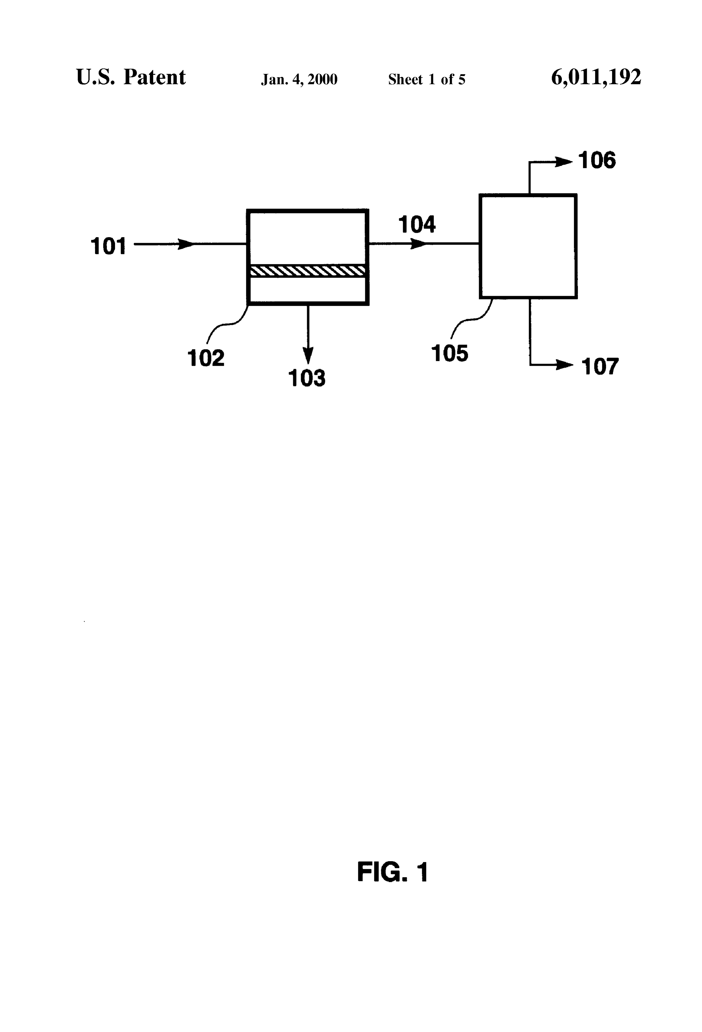
At intervals, the bed is regenerated and a waste light BRIEF DESCRIPTION OF THE DRAWINGS hydrocarbon Stream is removed. This stream typically, but 15 FIG. 1 is a Schematic drawing showing a basic embodi not necessarily, will be burnt as fuel. ment of the invention.
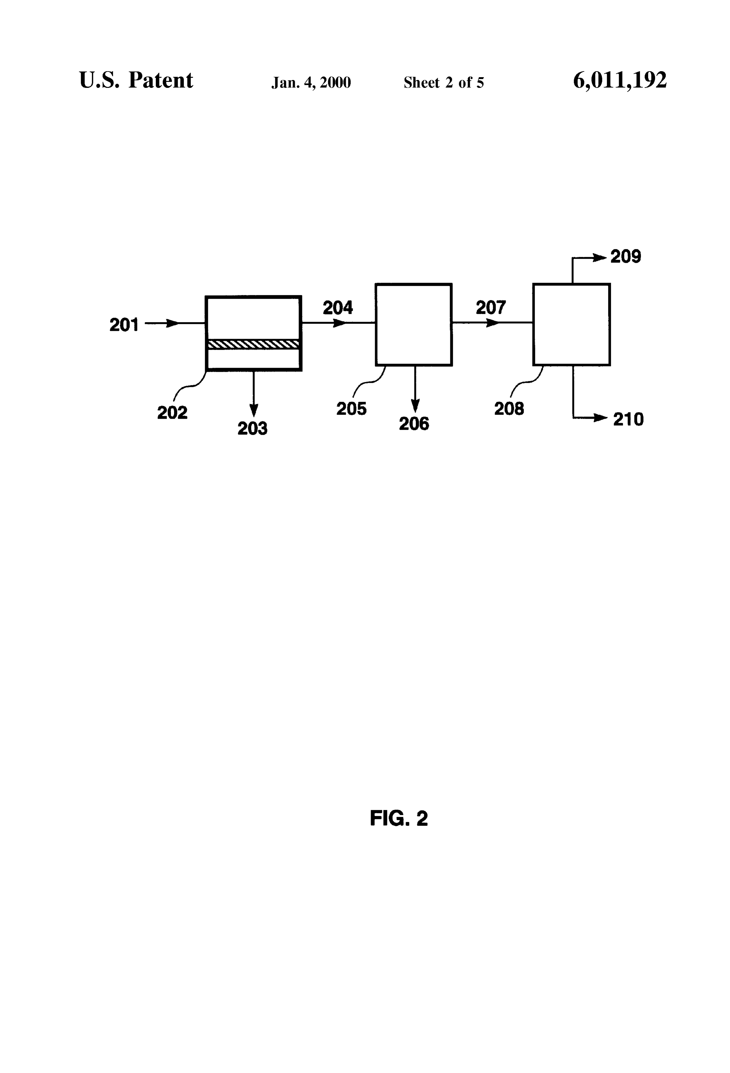
Additional Separation Steps may be carried out between the membrane Separation Step and the Selective adsorption theFIG. 2 is a Schematic drawing showing an embodiment of invention in which an ancillary treatment Step is included
Step as desired.
Specific exemplary Separations to which the process of between the membrane conditioning Step and the Selective adsorption Step.
the invention can be applied include, but are not limited to,
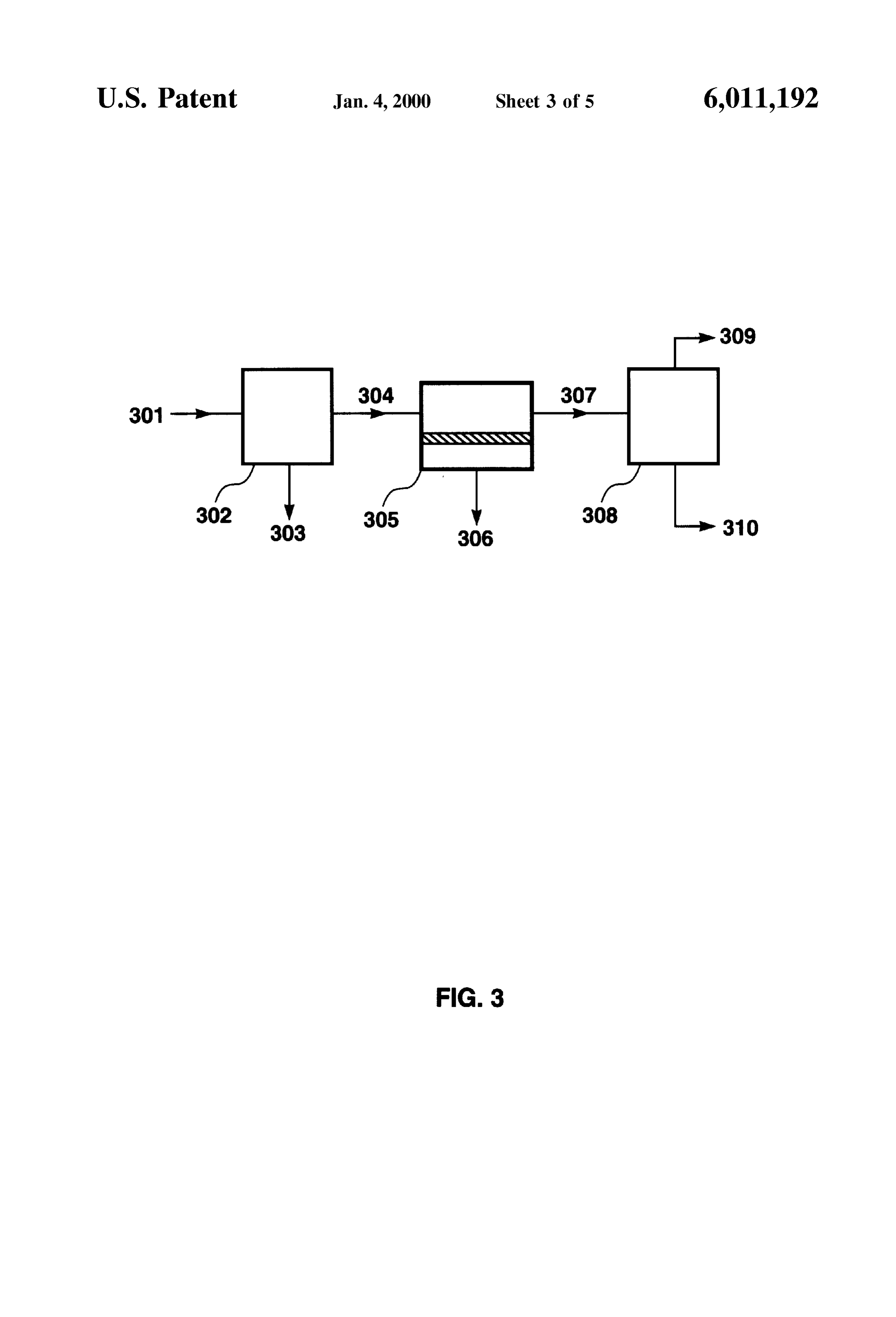
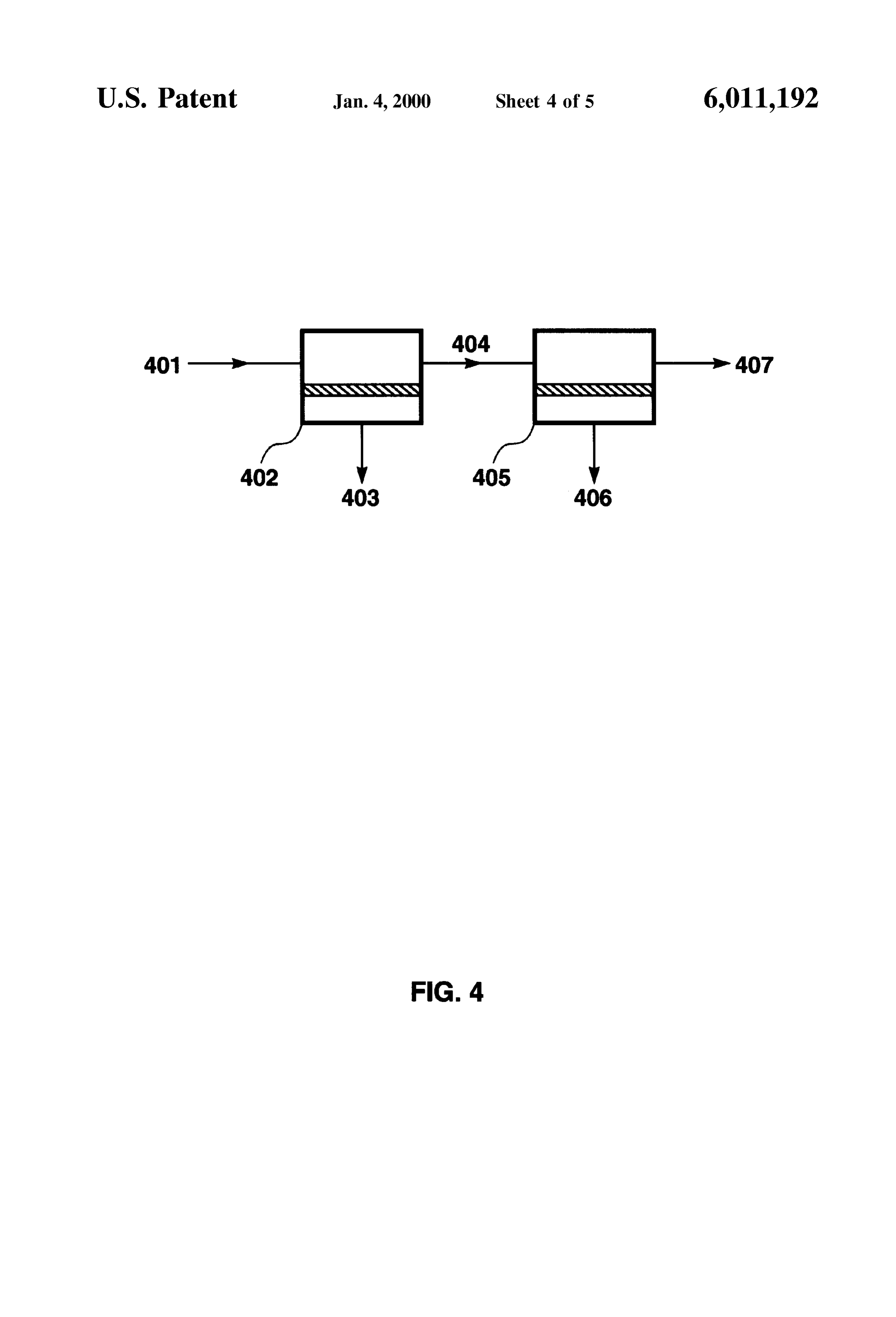
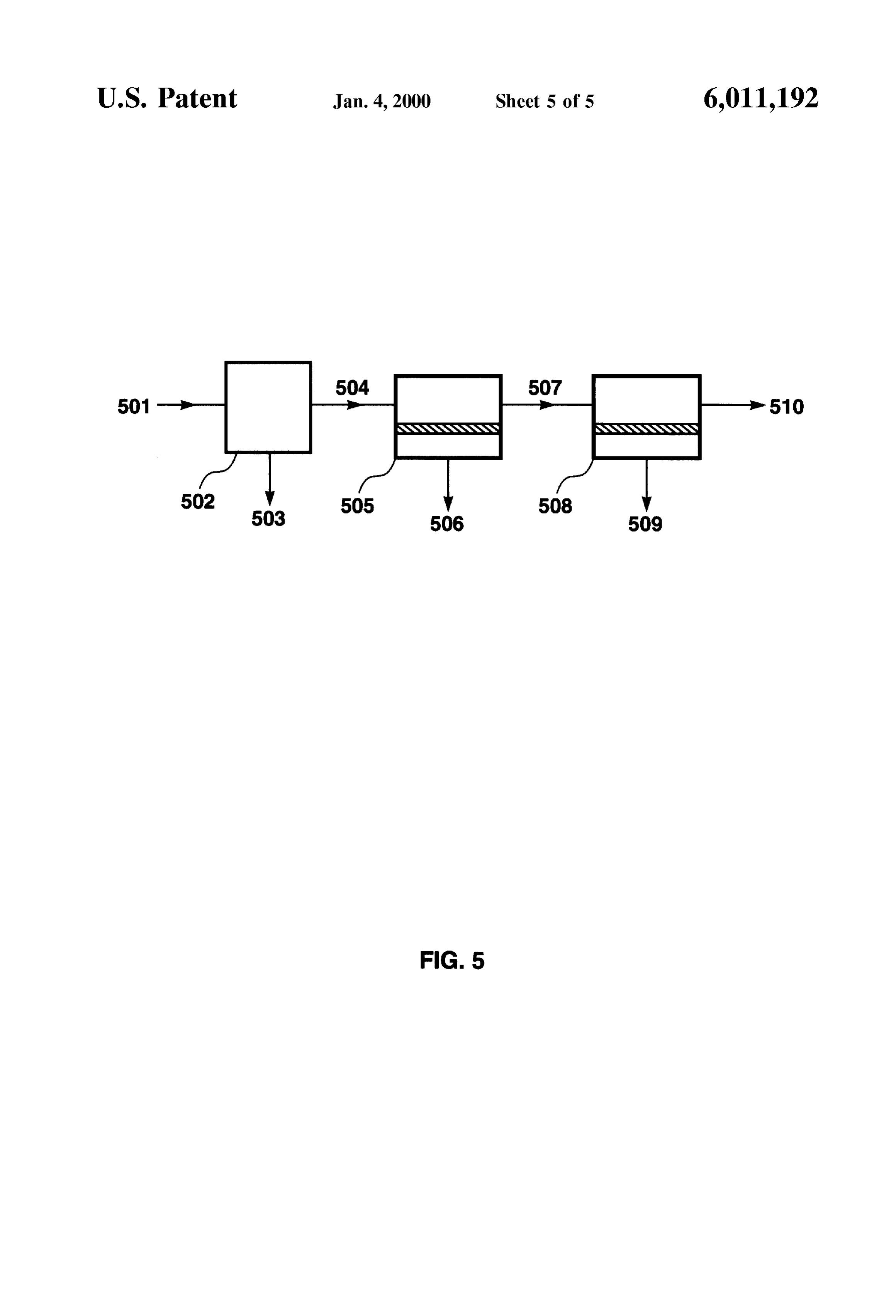
Separation of light hydrocarbons from hydrogen in off-gas FIG. 3 is a Schematic drawing showing an embodiment of Streams from: hydrocrackers, hydrotreaters of various kinds, the invention in which an ancillary treatment Step is included including hydrodeSulfurization units, coking reactors, cata upstream of the membrane conditioning Step. lytic reformers, catalytic crackers, specific isomerization, 25 FIG. 4 is a Schematic drawing showing an embodiment of alkylation and dealkylation units, Steam reformers, hydro the invention using two membrane Separation Steps. genation and dehydrogenation processes; and Steam crack FIG. 5 is a schematic drawing showing an embodiment of erS for olefin production. The invention can be applied to any the invention using two membrane Separation Steps, with an Streams containing hydrogen, methane and C-C hydro ancillary upstream treatment Step.
carbon in proportions to give rise to a dewpoint at 200 psia DETAILED DESCRIPTION OF THE of at least 10 C. The invention is especially useful, INVENTION however, for treating Streams that are neither very rich in heavier hydrocarbons nor very rich in hydrogen. By this, we The terms gas and vapor are used interchangeably herein. mean streams that contain no more than about 80% hydro The term dewpoint, unless otherwise explicitly Stated, gen and no more than about 10% Cs-Cs hydrocarbon. 35 means hydrocarbon dewpoint.
Absent the process of the invention, Such Streams are typically used as fuel gas. The invention provides Separation ingThe term C-C hydrocarbon means a hydrocarbon hav and recovery of the valuable hydrogen and heavier hydro atOmS. five carbon atoms and no more than eight carbon at least carbon components.
Furthermore, by recovering these components, the inven 40 noThe term light hydrocarbon means a hydrocarbon having more than four carbon atoms.
tion Substantially reduces the fuel gas load in the plant, in favorable cases by as much as 50% or more. In plants where The term heavier hydrocarbon means a hydrocarbon fuel gas generation is at capacity, the invention provides an having at least five carbon atoms. attractive debottlenecking capability, allowing throughput of The terms two-step and multistep as used herein mean an the unit operations generating the off-gas to be increased. 45 arrangement of membrane modules or banks of membrane In an alternative embodiment, the invention can be carried modules connected together Such that the residue stream out by using a hydrogen-Selective membrane instead of a from one module or bank of modules becomes the feed Selective adsorption Step for the hydrogen/methane Separa Stream for the next.
tion. In this case, the invention comprises the following The terms two-stage and multistage as used herein mean conditioning Step: 50 an arrangement of membrane modules or banks of mem (i) passing the gas as a feed stream across the feed side of brane modules connected together Such that the permeate a polymeric membrane having a feed side and permeate Stream from one module or bank of modules becomes the Side, and being Selective for hydrocarbons over hydro feedstream for the next.
gen, The term membrane array means a set of membrane (ii) withdrawing from the permeate side a permeate 55 modules or banks of modules connected in a multistep Stream enriched in C-C hydrocarbon compared with arrangement, multistage arrangement, or mixtures or com the gas, binations of these.
(iii) withdrawing from the feed side a conditioned residue The term product residue stream means the residue stream Stream comprising hydrogen and methane and having a exiting a membrane array when the membrane Separation dewpoint at 200 psia at least about 10 C. lower than 60 process is complete. This Stream may be derived from one the original dewpoint; and the following hydrogen/ membrane bank, or may be the pooled residue streams from methane Separation Step: Several membrane bankS.
(i) passing the conditioned gas as a Second feed Stream The term product permeate Stream means the permeate across the Second feed side of a Second polymeric Stream exiting a membrane array when the membrane Sepa membrane having a Second feed Side and a Second 65 ration process is complete. This Stream may be derived from permeate Side, and being Selective for hydrogen over one membrane bank, or may be the pooled permeate Streams hydrocarbons, from Several membrane banks.
Page 12
Percentages herein are by Volume unless otherwise Stated. these operations together, Such as in multi-stage reactors, The invention is a proceSS for treating a gas mixture where the first stage predominantly converts Sulfur com containing at least hydrogen, methane and a C-C hydro pounds and the Second Stage predominantly performs the carbon. Such gas mixtures are frequently encountered as cracking Step. In hydroprocessing, fresh feed is mixed with off-gas Streams from unit operations in oil refining, from hydrogen and recycle gas and fed to the reactor, where the petrochemical production, and Similar activities. The gas desired reactions take place in the presence of a Suitable mixture may contain these components in any proportions. catalyst. For example, hydrogen is consumed to form hydro AS non-limiting examples, the gas may be predominantly gen Sulfide from mercaptains and the like, to form paraffins hydrogen, Such as 80% hydrogen or more, with Small from olefins, and to open and Saturate aromatic rings. AS a result, light components formed include methane, ethane amounts of C and C. hydrocarbons, such as 10-20%, and and hydrogen Sulfide. The reactor effluent enters a separator, Smaller amounts of Cs-Cs hydrocarbons, Such as 1-5%; or usually at high pressure, from which a hydrogen-rich vapor may be predominantly a hydrocarbon mix, such as 80% or fraction is withdrawn and returned to the reactor. The more of C-C hydrocarbons, with 20% or less hydrogen. hydrogen demand varies, depending on the Specifics of the The gas mixture may also contain Secondary contaminants, operation being performed, and may be as low as 200 scf/bbl Such as hydrogen Sulfide, carbon dioxide, water vapor and 15 or less for desulfurization of naphtha or Virgin light other organic materials. The gas mixture has a hydrocarbon distillates, 500-1,000 scf/bbl for treating atmospheric resid, dewpoint, as measured at 200 psia, of at least about 10 C. upwards
This does not mean that the gas is at 200 psia before, during as high asof5,000-10,000 1,000 scf/bbl for treatment of vacuum resid, and scf/bl for hydrocracking.
or after treatment (although it could be), but merely serves Not all of this hydrogen is consumed in the reactions. to express the hydrocarbon content of the gas in a definite Reactors are generally run with an exceSS of hydrogen in the way. Many gas Streams to be treated by the invention have feed to protect the catalyst from coke formation, thereby higher dewpoints, such as 20° C., 30° C., 40° C. or 50° C., prolonging the cycle time of the reactor. Generous use of all as measured at 200 psia. hydrogen also promotes high levels of Sulfur removal and The primary goal of the process is to Separate the gas depresses the formation of unsaturated compounds, which mixture into three Streams: a purified hydrogen Stream, 25 tend to be of lower value in this context. useful as a hydrogen Source on-site or elsewhere; a heavier AS a function of these requirements, the light gas fraction hydrocarbon Stream, preferably recovered as increased prod recirculated uct or LPG, and a light hydrocarbon Stream, usable as a fuel hydrogen, andfrom the Separators to the reactorS is rich in Source, or for other treatment or disposal. Depending on the hydrogen. Other consist may of as much as 80 vol% or more components are typically C-C,
Specifics of the Stream and on economic, geographical and hydrocarbons, hydrogen Sulfide, heavier hydrocarbons, car other constraints, the proceSS may optionally be configured bon dioxide, nitrogen ammonia and other trace materials. If to emphasize the hydrogen recovery capability. In other certain of these components, such as the light hydrocarbons circumstances, the prime driver may be reducing the amount and hydrogen Sulfide, are allowed to build up in the reactor of fuel gas produced by a process. In yet other cases, 35 loop, they gradually change the composition of the reactor increased product yield or LPG production will be impor mix and adversely affect the product yield and the catalyst. tant. Those of skill in the art will appreciate Such consider To prevent this build-up, a portion of gas is usually purged ations and will be able to apply the teachings herein as from the reactor return loop. This gas is Submitted to one or appropriate to Specific gas mixtures and industrial circum more treatment Steps, typically further phase Separation and StanceS.
40 Stripping, and the light overhead gas from these operations
In its most basic aspect, the invention is a process that is pooled with other off-gas Streams and Sent to the gas involves a membrane Separation conditioning Step to reduce treatment plant or to the fuel line. The invention can be used the dewpoint of the gas by 10° C. or more, followed by a to treat these light ends to increase recovery of Cs-Cs Selective adsorption Step to Separate the methane and other hydrocarbons and/or hydrogen before the gas is burnt. light hydrocarbons from the hydrogen. The membrane Sepa 45 Another important exemplary application of the invention ration Step Serves as a gas conditioning Step to remove is in catalytic reforming, the primary goal of which is to components that may be harmful to the Selective adsorption improve the octane quality of gasoline feedstocks. The Step, particularly Cs-Cs hydrocarbons, and to reduce and reformer is a net hydrogen producer, and in most refineries change the nature of the load on the Selective adsorption hydrogen thus generated is used in other units, Such as the Step. 50 hydrotreaters. In the reformer, the n-paraffin components of In another aspect, the invention is apparatus for carrying Virgin or cracked naphthas are converted to higher octane out the process. iso-paraffins and aromatics. The proceSS is generally carried Although it can be used in any field where gas mixtures out in three reaction Zones, in each of which specific of hydrocarbons and hydrogen are found, the invention is reactions are favored. For example, the first Zone may expected to be of particular use in the fields of oil refining 55 perform, among other reactions, dehydrogenation of meth and petrochemical production. Those of skill in the art will ylcyclohexane to toluene, the Second Zone may perform appreciate that numerous opportunities exist for its employ dehydroisomerization, Such as conversion of heptane to ment in those areas, and that the brief discussion of a few toluene, and the third Zone may perform isomerization of applications that follows is intended to be exemplary rather normal to iso-heptane. Although the process is an overall than limiting. 60 producer of hydrogen, hydrogen is recycled back to the feed AS a first example, the major consumers of hydrogen in a to maintain the hydrogen-to-hydrocarbon ratio in the reac refinery are the hydroprocessing units. Hydroprocessing tors within a range to favor the desired reactions and to covers various refinery operations, including, but not limited prolong the catalyst life.
to, catalytic hydrodesulfurization (CHD), hydrotreating to The gaseous effluent from the reactor Series is cooled and remove other contaminants, pretreatment of reformer 65 Separated into liquid and vapor phases. The vapor phase may feedstocks, and hydrocracking to break down polycyclic be Subjected to other hydrogen purification Steps, and is aromatic compounds. Modern refineries often carry out divided into two streams, one for return to the reformer, the
Page 13
other for use elsewhere in the refinery. The invention can be The permeability of a gas or vapor through a membrane used as part of the vapor phase treatment, to enhance is a product of the diffusion coefficient, D, and the Henry's recovery of valuable products. law Sorption coefficient, k. D is a measure of the permeant's A third exemplary application is in isomerization, a broad mobility in the polymer; k is a measure of the permeant's term that covers a variety of Specific operations. In the Sorption into the polymer. The diffusion coefficient tends to refinery, isomerization is used to improve the quality of light decrease as the molecular size of the permeant increases, Straight-run gasoline by converting normal Cs and C par because large molecules interact with more Segments of the affins to iso-paraffins. Another important use is conversion polymer chains and are thus leSS mobile. The Sorption of n-butane to iso-butane for alkylate manufacture. Isomer coefficient depends, amongst other factors, on the condens ization is used in the petrochemical industry to convert 1O ability of the gas.
isomers of butene, pentene, hexene and other olefins to Depending on the nature of the polymer, either the dif preferred forms as feedstocks for other processes, Such as fusion or the Sorption component of the permeability may MTBE and TAME manufacture. Another important petro dominate. In rigid, glassy polymer materials, the diffusion chemical application of isomerization is the conversion of coefficient tends to be the controlling factor and the ability other Cs compounds into paraxylene, the starting feedstock 15 of molecules to permeate is very size dependent. As a result, for polyester manufacture. Although isomerization reactions glassy membranes tend to permeate Small, low-boiling themselves do not consume hydrogen, hydrogen is used in molecules, Such as hydrogen and methane, faster than larger, the isomerization reactor gas mix to protect the catalyst from more condensable molecules, Such as C organic mol coking, and Small amounts of hydrogen are consumed by ecules. For rubbery or elastomeric polymers, the difference Secondary reactions that take place. The layout of the in size is much less critical, because the polymer chains can process is often, therefore, Similar to those already be flexed, and Sorption effects generally dominate the per described; the effluent from the reactors is cooled and meability. Elastomeric materials, therefore, tend to permeate Separated into liquid and vapor phases, and, after purging as large, condensable molecules faster than Small, low-boiling necessary, the vapor phase is recirculated to the reactors. The molecules. Thus, most rubbery materials are Selective in invention can be used as described above to treat off-gases 25 favor of C3 hydrocarbons over hydrogen, and can be used from Separators or other treatment units to provide Selective in the invention.
additional recovery of hydrocarbons with little hydrogen However, for the Smallest, least condensable loSS. hydrocarbons, methane in particular, even rubbery polymers A fourth opportunity for our proce SS is in tend to be Selective in favor of hydrogen, because of the hydrodealkylation, principally benzene production from relative ease with which the hydrogen molecule can diffuse toluene. The toluene/benzene conversion is usually per through most materials. For example, neoprene rubber has a formed by cracking at high temperature, Such as above 600 Selectivity for hydrogen over methane of about 4, natural C., in the presence of hydrogen. Typically a molar ratio of rubber a selectivity for hydrogen over methane of about 1.6, hydrogen to hydrocarbon of about 4 is used, and the proceSS and Kraton, a commercial polystyrene-butadiene consumes as much as 1,500 Scf of hydrogen per barrel of 35 copolymer, has a Selectivity for hydrogen over methane of hydrocarbon processed. In the typical process, toluene, about 2.
make-up hydrogen and recycle hydrogen are heated and Any rubbery material that is Selective for C. hydrocar enter the reactor, where toluene and hydrogen react to form bons over hydrogen will provide Selective purging of these benzene and methane. The effluent is withdrawn from the components and can be used in the invention. Examples of reactor and passed through Separators that both cool and 40 polymers that can be used to make Such elastomeric reduce the pressure of the effluent. The hydrocarbon liquid membranes, include, but are not limited to, nitrile rubber, mixture that results is Stabilized, then the benzene product is neoprene, polydimethylsiloxane (Silicone rubber), chloro Separated from the heavier aromatics, at least part of which Sulfonated polyethylene, polysiliconecarbonate copolymers, is recycled to the reactor for further conversion. The vapor fluoroelastomers, plasticized polyvinylchloride, phase from the Separators is Subjected to additional hydro 45 polyurethane, cis-polybutadiene, cis-polyisoprene, poly gen purification if necessary and the remaining hydrogen is (butene-1), polystyrene-butadiene copolymers, Styrene/ returned for reuse in the reactor. AS can be seen, the butadiene/Styrene block copolymers, Styrene/ethylene/ opportunity again exists to apply our proceSS as part of the butylene block copolymers, and thermoplastic polyolefin treatment of overhead gases from the phase Separators or of elastomers.
the light ends from the stabilizer column. 50 The process of the invention is carried out using a The invention in a basic aspect is shown Schematically in membrane Selective for the C-C hydrocarbons over hydro FIG.1. It will be appreciated by those of skill in the art that gen. It is most preferred, although not essential, that the this, and the other figures described below, are very simple membrane be Selective for all hydrocarbons, including Schematic diagrams, intended to make clear the key aspects methane, over hydrogen, as this minimizes the loSS of of the invention, and that an actual process train will usually 55 hydrogen into the permeate Stream. include many additional components of a Standard type, To applicants knowledge, among the polymeric mem Such as heaters, chillers, condensers, pumps, blowers, other branes that perform gas Separation based on the Solution/ types of Separation and/or fractionation equipment, Valves, diffusion mechanism, Silicone rubber is the only material Switches, controllers, preSSure-, temperature-, level- and that is Selective in favor of methane over hydrogen, although flow-measuring devices and the like. 60 any polymeric membrane that is found to have a methane/ Referring now to FIG. 1, stream 101, the gas mixture hydrogen Selectivity greater than 1 can also be used as a containing hydrogen, methane and a C-C hydrocarbon, preferred membrane material. For example, other materials and having a dewpoint at 200 psia of at least 10 C., enters that might perhaps be found by appropriate experimentation the membrane separation step or unit, 102. The membrane to be methane/hydrogen Selective include other polysilox unit contains a membrane that exhibits a Substantially dif 65 CS.
ferent permeability for the C-C hydrocarbons than for Another class of polymer materials that has at least a few hydrogen. members that should be methane/hydrogen Selective, at least
Page 14
in multicomponent mixtures including other more condens as 30%, 40%, 50% or more higher than the feed, subject only able hydrocarbons, is the Superglassy polymers, Such as to the presence of any other slow-permeating components in poly(1-trimethylsilyl-1-propyne) IPTMSP) and poly(4- the feed. This can be accomplished by increasing the Stage methyl-2-pentyne)PMP). These differ from other polymeric cut of the membrane Separation Step, that is, the ratio of membranes in that they do not separate component gases by permeate flow to feed flow, to the point that little of anything Solution/diffusion through the polymer. Rather, gas transport except hydrogen is left in the residue stream. AS the Stage is believed to occur based on preferential Sorption and cut is raised, however, the permeate Stream becomes pro diffusion on the Surfaces of interconnected, comparatively gressively more diluted by the slower permeating compo long-lasting free-volume elements. Membranes and mod ules made from these polymers are less well developed to nents. limit,
This can be clearly Seen by considering that, in the if the stage-cut were allowed to go to 100%, all of the date; this class of materials is, therefore, less preferred than gas present in the feed would pass to the permeate side of the silicone rubber.
membrane
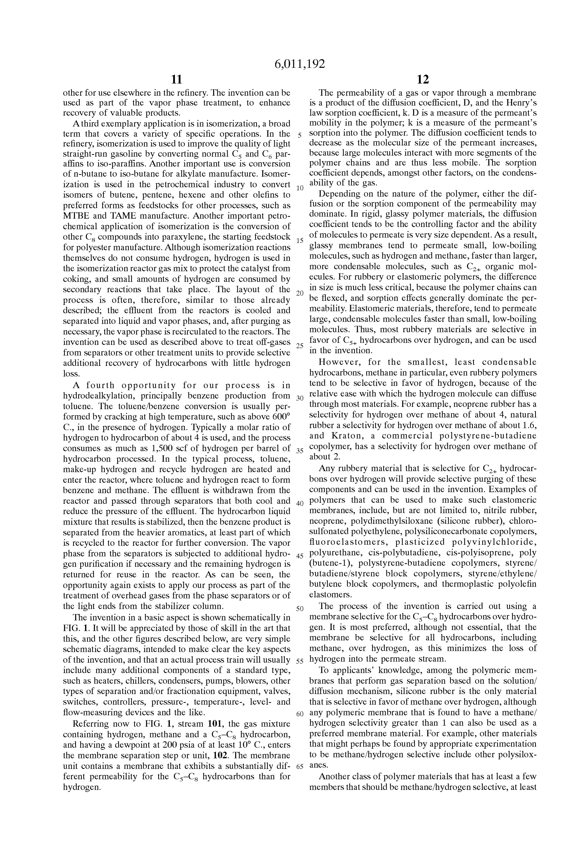
A third type of membrane that may optionally be used if Sition as the feed. and the permeate would have the same compo Since the purpose of the membrane the gas mixture contains hydrogen Sulfide is one in which the Separation Step is to condition
Selective layer is a polyamide-polyether block copolymers 15 ing certain components, while the gas by Selectively remov controlling the loSS of hydro having the general formula gen with those components, a very high Stage-cut, and hence a high hydrogen concentration in the residue, defeats the
purpose of the invention. Furthermore, it is not required for the membrane Separation Step to achieve any significant
Separation between the lightest hydrocarbons and hydrogen,
Since this separation is performed by the adsorption Step. It where PA is a polyamide Segment, PE is a polyether Segment is preferred, therefore, to keep the Stage-cut low, Such as and n is a positive integer. Such polymers are available below 50%, more preferably below 40% and most prefer commercially as Pebax(R) from Atochem Inc., Glen Rock, ably below 30%.
N.J., or as Vestamid(R) from Nuodex Inc., Piscataway, N.J. 25 On this basis, the residue stream, 104, will, generally, be These types of materials are described in detail in U.S. Pat. enriched in hydrogen compared with the feed, but typically No. 4,963,165, for example. Such membranes will remove only by a small amount, such as 1%, 2%, 5% or 10%. Thus, hydrogen Sulfide with a very high Selectivity, Such as 20 or the membrane conditioning Step provides only slight more, for hydrogen Sulfide over hydrogen. enhancement of the hydrogen content of the gas, and pro The membrane Separation Step is used to condition the gas vides little, if any, Significant Separation between the hydro mixture to facilitate the Selective adsorption Step that fol gen and the lightest hydrocarbons, Specifically methane. The lows; the purged materials are removed from the condition residue stream has a hydrocarbon dewpoint Substantially ing step as permeate stream 103. The membranes permeate below the dewpoint of the feed stream, 101. The lower the all Cs hydrocarbons, hydrogen Sulfide, carbon monoxide, hydrocarbon dewpoint, the easier will the gas be to treat in carbon dioxide, water vapor and ammonia faster than hydro 35 the Subsequent Selective adsorption Step, because compo gen. Thus, permeate Stream 103 is Substantially enriched in nents that are difficult to desorb have been reduced or hydrocarbons, and the other components mentioned above, removed. By substantially below, we mean that the dewpoint if they are present, and depleted in hydrogen, compared with of stream 104 at 200 psia is at least about 10 C. lower than feed stream 101. the dewpoint of stream 101 at 200 psia, preferably at least Those of skill in the art will appreciate that the membrane 40 about 20° C. lower, more preferably at least about 30° C. area and membrane conditioning Step operating conditions lower and most preferably at least about 40 C. lower. The can be varied depending on the components of interest to be amount of C-C hydrocarbon removal that this represents removed by the conditioning Step. For example, the con will depend, of course, on the Specific components present centration of Cs-Cs hydrocarbon components might be in the feed. AS a non-limiting example, in a stream contain raised from 2 vol% in the feed to 10 vol% in the permeate, 45 ing Cs, C, C, and Cs components, all at concentrations of and/or the hydrogen Sulfide concentration might be raised less than 1%, a 10° C. reduction in dewpoint might represent from 5% to 20%. Correspondingly, the hydrogen content removal of Cs only, a 20° C. reduction in dewpoint might may drop from 75 vol% in the feed to 50 vol% or less in represent removal of most Co-Cs, and a 40 C. reduction in the permeate. Keeping the hydrogen content in the permeate dewpoint might represent removal of essentially all C-C, low is desirable, because hydrogen lost here is not available 50 hydrocarbon components, plus Some lighter components. for recovery later in the Selective adsorption Step. Typically, Expressing the preferences for the residue stream charac it is possible, as illustrated in the examples Section below, to teristics in terms if removal of Cs-C hydrocarbons, it is meet the conditioning target of at least 10 C. dewpoint most preferred to remove at least 99% of all C-C, reduction, and at the same time keep the hydrogen loSS to no hydrocarbons, insofar as this will provide the most more than 20%, 10% or less of the total hydrogen content of 55 conditioning, and hence the most protection for the follow the feed Stream. ing Selective adsorption Step. However, depending on the The permeate Stream is withdrawn from the proceSS and composition of the feed Stream, in particular the proportions Subjected to further treatment or used as desired. Frequently, of the individual Cs-C hydrocarbons and the proportions of it will be convenient to cool and condense at least a portion hydrogen, this may result in undesirable hydrogen loSS into of the permeate for use as LPG (liquid petroleum gas), or to 60 the permeate. The tradeoff between acceptable levels of add it to the reactor product Stream. conditioning, acceptable levels of hydrogen in the permeate By Selectively removing non-hydrogen components, the and acceptable costs can be established by those of skill in proceSS results in a membrane residue Stream, 104, that is the art having regard to the teachings herein. In general, we enriched in hydrogen content compared with stream 101. Of prefer to run the membrane conditioning Step So as to course, the membrane Separation unit can be configured and 65 remove at least about 80%, more preferably at least about operated to provide a residue stream that has a significantly 90% of all C-C hydrocarbons in the feed to the selective higher hydrogen concentration compared with the feed, Such adsorption Step.
Page 15
A benefit of using rubbery or Superglassy membranes is An advantage of using a hydrogen-rejecting membrane is that they provide much higher transmembrane fluxes than that the Stream containing the hydrogen and light hydrocar conventional glassy membranes. For example, the perme bons remains on the high-pressure Side of the membrane. ability of silicone rubber to methane is 800 Barrer, compared Thus, residue Stream, 104, remains at or close to the preSSure with a permeability of less than about 10 Barrer for 6FDA 5 of Stream 101, Subject only to a slight pressure drop along polyimide or cellulose acetate. the feed Surface of the membrane modules. This means that The membrane may take any convenient form known in in many cases, Stream 104 can pass directly to the Selective the art. The preferred form is a composite membrane includ adsorption Step, 105, without additional compression, as ing a microporous Support layer for mechanical Strength and shown in FIG. 1. Alternatively, a compressor can be a Silicone rubber coating layer that is responsible for the included in line 104 to boost the pressure as necessary. Separation properties. Additional layerS may be included in The Selective adsorption Step may be carried out in any the Structure as desired, Such as to provide Strength, protect convenient manner known in the art, Such as by thermal the Selective layer from abrasion, and So on. Swing adsorption or pressure Swing adsorption (PSA). PSA The membranes may be manufactured as flat sheets or as is preferred. Selective adsorption Systems usually comprise fibers and housed in any convenient module form, including 15 a series of beds of a zeolite or similar material that will Spiral-wound modules, plate-and-frame modules and potted Selectively Sorbone or more components of the gas mixture. hollow-fiber modules. The making of all these types of The beds are connected in Such a way that each bed can be membranes and modules is well known in the art. Flatsheet Switched periodically from adsorption mode to regeneration membranes in Spiral-wound modules are our most preferred mode. As one bed or set of beds is taken off-line for choice. Since conventional polymeric materials are used for regeneration, another bed or Set of beds is Switched in So that the membranes, they are relatively easy and inexpensive to gas can be processed continuously. In the Sorption mode, prepare and to house in modules, compared with other types which is typically carried out at elevated pressure, Such as of membranes that might be used as hydrogen-rejecting 200 psia, 300 psia, 500 psia or above, light hydrocarbons are membranes, Such as finely microporous inorganic adsorbed onto the active beds. The gas exiting the bed, membranes, including adsorbent carbon membranes, 25 stream 106, has a high hydrogen content, such as 99 vol% pyrolysed carbon membranes and ceramic membranes. hydrogen or higher and can be used as a Source of hydrogen To achieve a high flux of the preferentially permeating as desired.
hydrocarbons, the Selective layer responsible for the Sepa When the adsorbing beds have been charged to the desired ration properties should be thin, preferably, but not level, they are Switched into desorption/regeneration mode. necessarily, no more than 30 um thick, more preferably no The desorption/regeneration Step can be carried out by any more than 20 um thick, and most preferably no more than 5 convenient techniques known in the art. Such techniques tim thick. If Superglassy materials are used, their perme include, but are not limited to, passing a displacement gas abilities are So high that thicker membranes are possible. cocurrently through the bed to Sweep out unadsorbed gas Depending on the composition of the membrane feed from the Void spaces, cocurrent depressurization of the bed Stream 101, a Single-stage membrane Separation operation 35 to position the mass transfer front appropriately, counter may condition the feed Stream adequately. However, if current depressurization to remove previously adsorbed gas, needed, membrane unit 102 may contain an array of mod and countercurrent purging to complete regeneration of the ules. If the residue Stream requires further conditioning, it bed for reuse.
may be passed to a Second bank of membrane modules for Depressurization of the bed during these Steps may take a Second processing Step. If the permeate Stream requires 40 place by multiple reductions in pressure, as is known in the further concentration, Such as to facilitate recovery of LPG, art. Preferably, the adsorption Step is carried out at a pressure it may be passed to a Second bank of membrane modules for no higher than about 500 psia, and more preferably in the a Second-stage treatment. Such multistage or multistep range 50-500 psia. Removal of Void Space gas and posi processes, and variants thereof, will be familiar to those of tioning of the mass transfer front is preferably carried out at skill in the art, who will appreciate that the membrane 45 a pressure in the range 50-250 psia, and countercurrent Separation Step may be configured in many possible ways, desorption is preferably carried out at a preSSure no lower including Single-stage, multistage, multistep, or more com than 15 psia, more preferably in the range 15-75 psia, yet plicated arrays of two or more units in Serial or cascade more preferably no lower than about 30 psia and most arrangements. If an array of membrane modules is used, the preferably no lower than about 50 psia. Stage-cut preferences cited above for obtaining good Cs-Cs 50 By way of non-limiting example, a typical bed cycle may hydrocarbon removal and low loss of hydrogen refer to the be: (i) adsorption at 500 psia; (ii) depressurization to 200 overall Stage-cut of the array. In other words, the Stage-cut psia under cocurrent flow conditions; (iii) depressurization is the ratio of the total product permeate flow to raw feed to 50 psia under countercurrent flow conditions; (iv) purging flow to the first membrane bank in the array. at 50 psia, (v) repressurization. A driving force for transmembrane permeation is pro 55 Since the heavier hydrocarbon components and other Vided by a pressure difference between the feed and perme relatively condensable components are removed by the ate Sides of the membrane. At least Some of the gas Streams conditioning Step, operation of the desorption/regeneration to be treated by the invention, Such as those emerging from Step at Subatmospheric pressure, while optional, is not various refinery operations, will be at elevated pressure, generally necessary. It is normally possible, by following the such as 100 psia, 200 psia, 500 psia or above. Feed pressures 60 teachings herein, to operate with the lowest pressure in the at this level will be adequate in many instances to provide desorption/regeneration Step no lower than 15 psia, more acceptable membrane performance. In favorable cases Such preferably no lower than 25 psia, and most preferably no as this, the membrane Separation unit requires no additional lower than about 50 psia.
compressors or other pieces of rotating equipment. If the The gases that are removed during the desorption/ preSSure of Stream 101 is insufficient to provide adequate 65 regeneration Steps are shown generally in FIG. 1 as Stream driving force, a compressor may be included in line 101, as 107. Stream 107 may be a single stream, as shown, or more discussed in more detail below. commonly will be several streams from the individual steps.
Page 16
This stream or Streams typically comprise mostly methane not required. If desired, however, an ancillary treatment and other light hydrocarbons, and are Sent to the fuel gas prior to the membrane conditioning Step may be added as line, but can optionally pass to other destinations on a convenient to Specific circumstances. As a non-limiting case-by-case basis as the composition of the gas renders it example, the Stream may be Saturated with water vapor, and Suitable. it may be preferred to remove the water in an upstream Step, Depending on the original gas composition, the process of So that the membrane permeate Stream is dry. In this case the FIG. 1 can reduce the gas sent to the fuel line by 50% or ancillary treatment Step may be a dehydration Step, Such as more as shown in the Examples. A useful result is that Some glycol absorption, Silica gel adsorption or adsorption onto a plants that were previously bottlenecked by fuel gas pro molecular Sieve. Of these, dehydration by molecular Sieve is duction are able to increase throughput in the reactors, preferred, as the Sieves are highly Selective and can be thereby increasing product yield. regenerated easily using a hot gas stream. It will be appreciated by those of skill in the art that AS a Second non-limiting example, the feed Stream to the ancillary treatments can be included to enhance the perfor process may be at comparatively low preSSure, Such as mance of the invention. An alternative embodiment of the atmospheric pressure (15 psia) or just a little above atmo invention in this aspect is shown in FIG. 2. Referring to this 15 Spheric pressure, Such as 20 psia, 30 psia or 50 psia. The figure, Stream 201, containing hydrogen, methane and a treatment of Such a stream will be aided by compressing the Cs-C hydrocarbon, and having a dewpoint at 200 psia of at Stream to a higher preSSure, Such as 100 psia, 200 psia, 300 least about 10 C., enters the membrane separation step or psia or 500 psia, before passing the gas into the membrane unit, 202. AS before, the membrane unit contains a mem conditioning Step. In Situations where the gas contains brane that exhibits selectivity in favor of Cs-C hydrocar Significant amounts of the Cs-C hydrocarbons, Such as a bons over hydrogen, and all the issues, considerations, few percent or more, compression may raise the dewpoint choices and preferences discussed above with regard to the temperature considerably. Thus, the ancillary treatment Step membrane Separation Step of FIG. 1 apply equally to this could include compression followed by cooling, resulting in embodiment. Optionally, a compressor may be installed in condensation of a portion of the heavier hydrocarbon com line 201 to raise the gas pressure to any desired pressure. The 25 ponents in liquid form. To condense the heavier hydrocarbon Cs+ hydrocarbons permeate the membrane and are removed fraction, it is usually possible, and is preferred, to use only as Cs+ hydrocarbons concentrated stream 203. The remain modest cooling of the Stream, Such as to no lower than about ing gas is withdrawn from the feed Side of the unit as residue 20° C. or 10° C.
Stream 204. This stream passes as feed into ancillary treat An embodiment in which an ancillary treatment is pro ment unit, 205. This unit carries out separation of hydrogen Vided prior to the membrane conditioning Step is shown in from the remaining hydrocarbons in stream 204 to form two FIG. 3. Referring to this figure, stream 301, containing streams, 206, which is withdrawn, and 207, which passes to hydrogen, methane and Cs-Cs hydrocarbons, and having a the Selective adsorption Step. Any treatment that is able to dewpoint at 200 psia of at least 10 C., passes as feed to perform a separation of hydrogen from hydrocarbons may ancillary treatment unit, 302, adapted to perform any desired be used for step 205. Such treatments include, but are not 35 treatment of the raw gas, including dehydration, removal of limited to, absorption of the hydrocarbons into a suitable heavy hydrocarbon liquid, and removal of other contami medium, Such as a hydrocarbon liquid or the like, further nants. The step results in a stream 303, which is withdrawn. Separation by a hydrocarbon-Selective membrane, and mem In the case of dehydration, stream 303 comprises water. In brane Separation by a hydrogen-Selective membrane, Such as the case of compression/condensation, Stream 303 com a cellulose acetate membrane, a polyimide membrane or the 40 prises C-C hydrocarbons. This stream can be directed to like. Treatments of this type are very familiar to those of skill any appropriate destination, depending to Some extent on the in the art. For example, if the ancillary treatment is Separa Source of the gas being treated. Frequently it is possible to tion by a hydrogen-Selective membrane, the membrane unit direct stream 303 to a fractionator, stabilization column, can be configured to recover a permeate Stream of high debutanizers or the like that is already in use in the plant. For hydrogen purity, leaving a residue stream that Still has a 45 example, if the gas is from a catalytic reformer, the Cs-Cs comparatively high hydrogen content. In this case, the hydrocarbon components recovered here can be added to the residue stream will pass on as stream 207 for treatment in the reforrnate and will increase overall product yield. selective adsorption step, 208, and stream 206 will form an The remainder of the stream passes on as stream 304 to additional high purity hydrogen product Stream. the membrane separation step or unit, 305. In the case of Alternatively, but less preferably, the residue light hydro 50 compression/condensation, Stream 304 is now Saturated with carbon stream is withdrawn as stream 206, and the hydrocarbons under the prevailing preSSure and temperature hydrogen-enriched Stream, 207, passes on for further treat conditions. Even though the Stream is Saturated, however, it ment. can be passed Safely to the membrane conditioning Step, Stream 207 passes into selective adsorption step 208, because the membranes used are able to handle Such which may be carried out in any convenient manner, Such as 55 StreamS.
described in relation to FIG. 1 above. The purified hydrogen AS before, the membrane unit contains a membrane that product stream, 209, is withdrawn for use as desired, and the exhibits selectivity in favor of Cs hydrocarbons over desorbed light hydrocarbons are withdrawn as stream 210. hydrogen, and all the issues, considerations, choices and Embodiments of this type are particularly useful and pre preferences discussed above with regard to the membrane ferred for treating gases with an initially low hydrogen 60 Separation Step of FIG. 1 apply equally to this embodiment. content, Such as less than about 40% hydrogen, to boost the The Cs hydrocarbons permeate the membrane and are hydrogen content of the feed to the Selective adsorption Step, removed as Cs hydrocarbons concentrated stream 306. The such as to 60% hydrogen or above. remaining gas is withdrawn from the feed side of the unit as AS Stated above, the preferred membranes used in the residue stream 307, and passes to the Selective adsorption invention permeate hydrocarbons, hydrogen Sulfide and 65 step, 308. which may be carried out in any convenient water vapor preferentially, So pretreatment Steps before the manner, Such as described in relation to FIG. 1 above. The membrane Separation Step to remove these components are purified hydrogen product stream, 309, is withdrawn for use
Page 17
as desired, and the desorbed light hydrocarbons are with membrane separation step, 405, without additional drawn as stream 310. compression, as shown in FIG. 4. Alternatively, a compres When the ancillary treatment Step is compression/ Sor can be included in line 404 to boost the pressure as condensation, the scheme shown in FIG. 3 will produce two neceSSary.
Cs hydrocarbon Streams, liquid Stream 303 and permeate The second membrane separation step, 405, is used to vapor stream 306. In this case, it is preferred to return Separate hydrogen from methane and other light hydrocar permeate vapor stream 306 to the inlet of the compression/ bons. The membranes used in this Second Step are different condensation Step, So that all of the Cs hydrocarbon is from the membranes used in the conditioning Step in that recovered in stream 303. Arrangements of this type in which they are Selective in favor of hydrogen over hydrocarbons. a compression/condensation Step and a membrane Separa AS explained above, the permeability of a gas or vapor tion Step are integrated together are described, for example, through a membrane is a product of the diffusion coefficient, in U.S. Pat. No. 5,199,962, incorporated herein by reference. D, and the Henry's law Sorption coefficient, k, and the In another aspect, the invention can be carried out by diffusion coefficient tends to decrease as the molecular size using a hydrogen-Selective membrane instead of a Selective of the permeant increases.
adsorption Step for the light hydrocarbon/hydrogen Separa 15 In glassy polymers, the diffusion coefficient tends to tion. In this case, the first membrane Separation Step Serves dominate, and glassy membranes tend to be Selective in as a conditioning Step to protect the hydrogen-Selective favor of Small, low-boiling molecules. Thus for this step, the membrane used for the hydrogen/light hydrocarbon Separa preferred membranes are made from glassy polymer mate tion from damage caused by exposure to heavier rials that will pass hydrogen preferentially over methane and hydrocarbons, acid gases or water vapor. A Schematic draw the other light hydrocarbons. Such membranes are well ing of this embodiment of the invention is shown in FIG. 4. known in the art and are described, for example, in U.S. Pat. Referring to this figure, Stream 401, the gas mixture con Nos. 4,230,463, to Monsanto, and 3,567,632 to DuPont. taining hydrogen, methane and a C5 is hydrocarbon, and Suitable membrane materials include, but are not limited to, having a dewpoint at 200 psia of at least 10 C., enters the cellulose esters, polysulfone and polyimide. It is preferred membrane Separation Step or unit, 402. If the preSSure of 25 that the membranes exhibit a hydrogen/methane Selectivity Stream 401 is insufficient to provide adequate driving force, of at least about 5, more preferably at least about 10, and a compressor may be included in line 401. The membrane most preferably at least about 50. Selectivities at least as unit contains a membrane that is Selective in favor of the high as this can be provided by modern commercial poly Cs-C hydrocarbon Over hydrogen. This membrane Separa imide membranes, for example. It is also preferred that the tion Step corresponds to the membrane Separation Step in membranes exhibit a hydrogen flux of at least about 1x10 FIG. 1, and all the issues, considerations, choices and cm (STP)/cm’s cmHg, more preferably at least about preferences discussed above with regard to the membrane 10x10 cm (STP)/cm’s cmHg, and most preferably at Separation step of FIG. 1 apply equally to this embodiment. least about 100x10 cm (STP)/cm's cmHg. In particular, it is most preferred that the membrane be The hydrogen/methane Separation membranes may take Selective for all hydrocarbons, including methane, over 35 any form known in the art. The preferred glassy materials hydrogen, as this minimizes the loss of hydrogen into the that provide good hydrogen/methane Selectivity tend to have permeate Stream. low permeabilities compared with the conditioning The preferred membranes for use in this step are rubbery membranes, Such as a hydrogen permeability of only 10 membranes and Superglassy membranes, and the most pre Barrer. The preferred form for the membranes is, therefore, ferred membrane material is silicone rubber. AS before, the 40 integrally Skinned asymmetric hollow fibers, which can polyamide-polyether block copolymerS may be particularly provide both a very thin Selective skin layer and a high Suitable if the gas mixture contains hydrogen Sulfide. packing density, to facilitate use of large membrane areas. Since the conditioning membranes permeate all Cs AS an alternative to polymeric membranes, hydrogen hydrocarbons, hydrogen Sulfide, carbon monoxide, carbon Selective membranes may also be chosen from inorganic dioxide, water vapor and ammonia faster than hydrogen, the 45 membranes, including ceramic membranes, described in permeate Stream, 403, is Substantially enriched in U.S. Pat. No. 366,081, and subsequently in many more hydrocarbons, and the other components mentioned above, recent patents, and metal membranes, described in U.S. Pat. if they are present, and depleted in hydrogen, compared with No. 1,174,631, and more recently in U.S. Pat. No. 4,857, feed stream 401. Permeate stream 403 is withdrawn and sent 080, incorporated herein by reference, which describes to any appropriate destination as discussed above. 50 particularly preferred metal membranes. The conditioning membrane area and conditioning Step AS with the conditioning Step, the hydrogen/methane operating conditions can be varied to Suit the Specific Separation Step may include a single-stage membrane unit or circumstances of the Separation, as discussed above, and the an array of modules in a multistage, multistep or combina result will be that the permeate Stream has a much higher tion design.
Cs-C hydrocarbon content and a much lower hydrogen 55 The permeate Stream, 406, is the hydrogen product content than the feed. The residue stream, 404, has a much stream. The concentration of hydrogen in stream 406 lower C-C hydrocarbon content, and a slightly enriched depends on the composition of Stream 404 and the Specifics hydrogen content, such as 1%, 2%, 5% or 10% higher than of the membrane Separation Step. It is preferred to operate the feed stream 401. the hydrogen/methane Separation Step to achieve a hydrogen AS before, the membranes and modules may take any 60 product Stream containing at least 90% hydrogen, more convenient forms, and the membrane Separation Step may be preferably at least 95% hydrogen and most preferably at configured to include a single-stage operation, or an array of least 98% hydrogen. Those of skill in the art will appreciate multiple Stages and/or Steps. that the highest permeate hydrogen concentration is Residue stream 404 remains at or close to the pressure of achieved with the lowest hydrogen recovery from feed to Stream 401, Subject only to a slight pressure drop along the 65 permeate and Vice versa, and that the optimum balance feed Surface of the membrane modules. This means that in between recovery and purity will vary from circumstance to many cases, Stream 404 can pass directly to the Second circumstance.
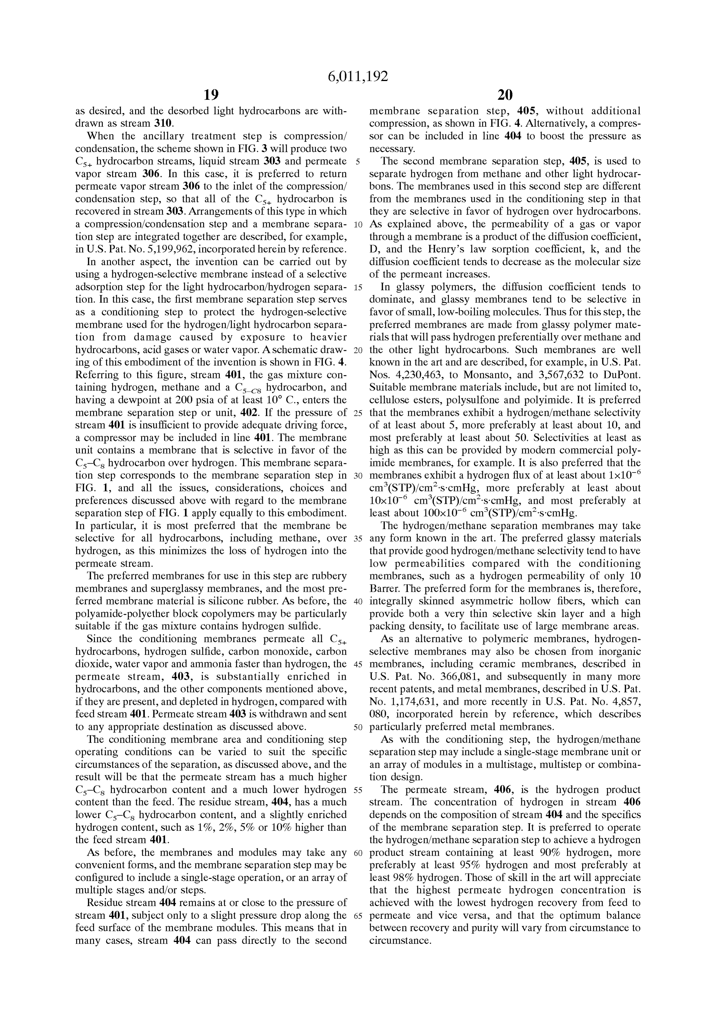
Page 18
The residue stream, 407, is enriched in light hydrocarbons -continued and depleted in hydrogen compared with Stream 404 and is usually directed to the fuel gas line. The same considerations Component Content (vol%) and benefits in terms of product recovery and reduction in Cs hydrocarbons 0.5 Cs-C hydrocarbons content = fuel gas generation as discussed above with respect to the C. hydrocarbons 0.4 1.5% embodiment of FIG. 1 apply to this embodiment. C, hydrocarbons O.3
It is also possible to incorporate ancillary treatments, Cs hydrocarbons O.3 upstream, downstream or between the membrane condition ing Step and the membrane hydrogen/methane Separation The dewpoint of such a stream at 50 psia is 21 C. It was Step, following the same general principles as in the embodi then assumed that the Stream was compressed to 200 psia. ments that use a Selective adsorption Step. FIG. 5 shows a This raises the dewpoint to 48 C.
representative embodiment of this type, using an upstream A computer calculation was performed to model a mem treatment Step. Referring to this figure, Stream 501, passes as brane feed to ancillary treatment unit, 502, adapted to perform any Stream conditioning Step applied to the treatment of this desired treatment of the raw gas, including dehydration, 15 formedtousing reduce the dewpoint. The calculation was per a modeling program, ChemCad III removal of heavy hydrocarbon liquid, and removal of other (ChemStations, Inc., contaminants. The step results in a stream 503, which is membrane SeparationHouston, modeling
Tex.), modified by in-house programs. The membrane withdrawn. Choices of treatment, Stream compositions and used for the conditioning was assumed to be a Silicone disposition are as discussed above with respect to FIG. 3. rubber membrane providing the following pressure The remainder of the stream passes on as stream 504 to the normalized fluxes:
membrane separation step or unit, 505. In the case of compression/condensation, Stream 504 is now Saturated with hydrocarbons under the prevailing pressure and temperature Hydrogen 100 x 10 cm (STP)/cm’ sec cmHg conditions. Even though the Stream is Saturated, however, it Methane 140 x 10 cm (STP)/cm2 sec cmHg can be passed Safely to the membrane conditioning Step, 25 Ethane 350 x 10 cm (STP)/cm2 sec cmHg because the membranes used are able to handle Such Propane 600 x 10 cm (STP)/cm’ sec cmHg StreamS.
AS before, the membrane unit contains a membrane that n-Hexane 2,500 x 10 cm (STP)/cm sec cmHg exhibits selectivity in favor of Cs hydrocarbons over n-Heptane 3,000 x 10 cm (STP)/cm’ sec cmHg hydrogen, and all the issues, considerations, choices and in-Octane 3,000 x 10 cm (STP)/cm’ sec cmHg preferences discussed above with regard to the membrane
Separation Step of FIG. 1 apply equally to this embodiment. The results of the calculations are shown in Table 1. The The Cs hydrocarbons permeate the membrane and are stream numbers correspond to FIG. 1. removed as Cs hydrocarbons concentrated stream 506. The remaining gas is withdrawn from the feed Side of the unit as 35 TABLE 1. residue stream 507, and passes to the membrane hydrogen/ methane separation step, 508. which may be carried out in Stream
Flow (scfm)
any convenient manner, Such as described in relation to FIG. Mass flow (Ib/h) 131 67 64 4 above. The purified hydrogen product stream, 509, is Temp. (C.) 47.8 47 47 withdrawn for use as desired, and the light hydrocarbon fuel 40 Pressure (psia) 2OO 2OO 2O gas stream is withdrawn as stream 510. Component (mol%):
When the ancillary treatment Step is compression/ Hydrogen 8OO 85.O 64.65 condensation, the scheme shown in FIG. 5 will produce two Methane 1OO 982 10.57 Cs hydrocarbon Streams, liquid Stream 503 and permeate Ethane 5.0 3.46 9.72 vapor stream 506. It is preferred to return permeate vapor 45 Propane 2.0 1.02 5.02
stream 506 to the inlet of the compression/condensation n-Pentane 0.5 O.11 1.70 Step, So that all of the Cs hydrocarbon is recovered in n-Hexane 0.4 O.08 1.39 Stream 503. n-Heptane O.3 O.05 1.06 The invention is now further described by the following in-Octane O.3 O.05 1.08 examples, which are intended to be illustrative of the 50 invention, but are not intended to limit the Scope or under The conditioned stream, 104, has a total Cs-C hydro lying principles in any way. carbon content of only 0.29%, and was calculated to have a EXAMPLE 1. dewpoint of 12 C. The C-C hydrocarbon flow in the
conditioned Stream is 0.21 Scfm, compared with 1.5 Scfm in
Calculations were performed to show the effect of com the feed. This represents a C-C hydrocarbon removal of pressing a low-pressure fuel gas Stream to facilitate hydro 86%. The hydrogen loss into the permeate in this case is gen recovery. The Stream was assumed to be at a pressure of about 20%.
50 psia and to have the following Volume composition: The conditioned Stream is Suitable for passing into the 60 selective adsorption step, 105.
Component Content (vol%) EXAMPLE 2 Hydrogen 8O The calculations of Example 1 were repeated, this time C. hydrocarbons 1O
C. hydrocarbons 5 assuming that the feed stream is cooled to 25 C. before Cs hydrocarbons 2 65 passing it into the conditioning membrane unit, according to C. hydrocarbons 1.5 the scheme of FIG. 3. The ancillary treatment step, box 302, now represents simple air or water cooling, and box 305
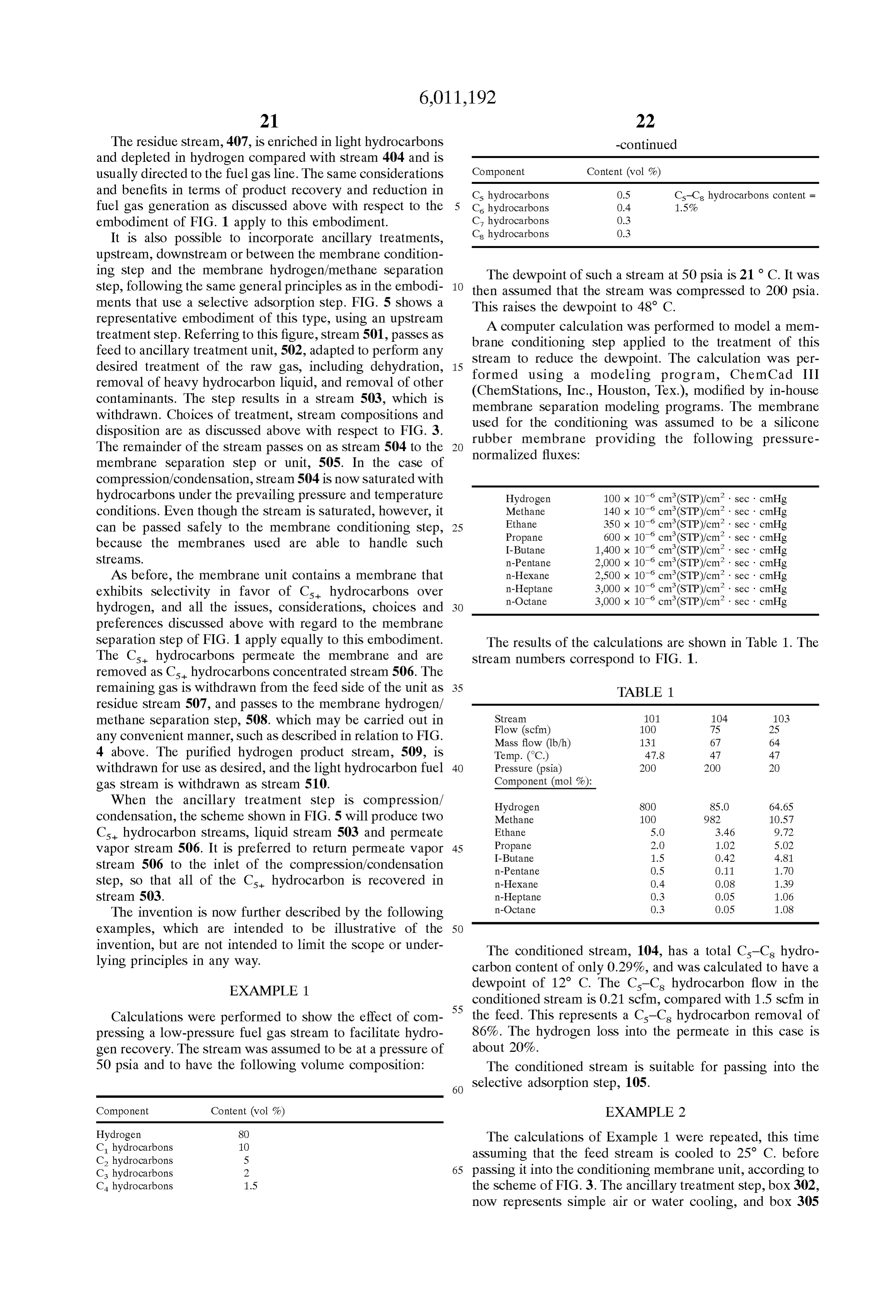
Page 19
represents the membrane conditioning step. Cooling to 25
C. condenses a portion of the feed Stream, represented by TABLE 3 stream 303, leaving an uncondensed portion, 304, which is Stream 101 104 103 at 200 psia and 25 C., and saturated with hydrocarbons. The membrane conditioning Step was again assumed to be car Flow (scfm) 1OO 88 11 ried out using a Silicone rubber membrane providing the Mass flow (Ib/h) 115 88 28
Same permeation properties as in Example 1. The results of Pressure (psia) 2OO 2OO 2O the calculations are shown in Table 2, where Stream numbers Component (mol%):
correspond to FIG. 3. Hydrogen 80.8 83.O 63.75
TABLE 2 Ethane 5.0 4.31 10.65
Stream 301 304 3O3 307 306 I-Butane 1.4 O.84 6.O7
Flow (scfm) 1OO 99 1. 76 23 15 n-Hexane O.18 O.09 O.91 Mass flow (Ib/h) 131 121 1O 66 55 n-Heptane O.O6 O.O3 O.29 Temp. (C.) 170 25 25 24 24 in-Octane O.O2 O.O1 O.10 Pressure (psia) 2OO 2OO 2OO 2OO 2O
Component (mol%):
Hydrogen 8O.O 80.5 O.84 85.0 66.O
Methane 1.O.O 1.O.O O.75 9.83, 17.79 EXAMPLE 4 Ethane 5.0 5.0 2.12 3.50 9.92
Propane 2.0 2.0 2.99 1.03 5.1
I-Butane 1.5 1.47 5.41 O.43 4.83 The calculations were repeated, assuming a Stage-cut of n-Pentane 0.5 O.45 8.09 O.10 1.57 n-Hexane 0.4 O.29 16.98 O.O6 1.05 17%, provided by a membrane area of 6.5 mi. The results of n-Heptane O.3 O.14 25.71 O.O2 O.49 25 the calculations are shown in Table 4. The stream numbers in-Octane O.3 O.O6 37.11 O.O1 O.23 correspond to FIG. 1.
TABLE 4
In this case, the conditioned membrane residue Stream, Stream 101 104 103 307, has a C-C hydrocarbon content of 0.19% and a calculated dewpoint of -5° C. The removal of C-C, Flow (scfm) 1OO 82 17
hydrocarbons by the conditioning is 91% and the combined Temp. (C.) 1O 9.4 9.4 hydrogen loss into the condensate stream and the permeate Pressure (psia) 2OO 2OO 2OO stream is about 19%. The conditioned stream would again be 35 Component (mol%):
Suitable for treatment by a Selective adsorption Step. Hydrogen 80.8 84.O 95.29
EXAMPLES 3-7 Propane 2.O 1.26 5.48
A set of calculations was performed to show the effect of 40 n-Hexane O.18 O.O6 O.78 membrane Stage-cut (the percentage of the feed gas perme n-Heptane O.O6 O.O2 O.25
ating the membrane). The feed Stream was assumed to be at a pressure of 200 psia, at its dewpoint temperature of 10°C., and to have the following composition: 45
EXAMPLE 5
Component Content (vol%)
Hydrogen 80.8 The calculations were repeated, assuming a Stage-cut of C. hydrocarbons 1.O.O
23%, provided by a membrane area of 9 m. The results of
C. hydrocarbons 5.0 the calculations are shown in Table 5. The stream numbers Cs hydrocarbons
C. hydrocarbons
correspond to FIG. 1.
Cs hydrocarbons O.38 Cs-C hydrocarbons content =
C. hydrocarbons O.18 O.64% TABLE 5 C, hydrocarbons O.O6
Cs hydrocarbons O.O2 55 Stream 101 104 103
The membrane and its properties were assumed to be as Temp. (C.) 1O 9 9
in Example 1. Component (mol%):
EXAMPLE 3 Methane 10.1 9.85 10.93
The calculations were performed assuming an 11% stage I-Butane 1.4 O.43 4.76 cut provided by a membrane area of 4.5 m. The results of 65 n-Pentane O.38 O.09 1.34 the calculations are shown in Table 3. The stream numbers n-Hexane O.18 O.04 O.67 correspond to FIG. 1.
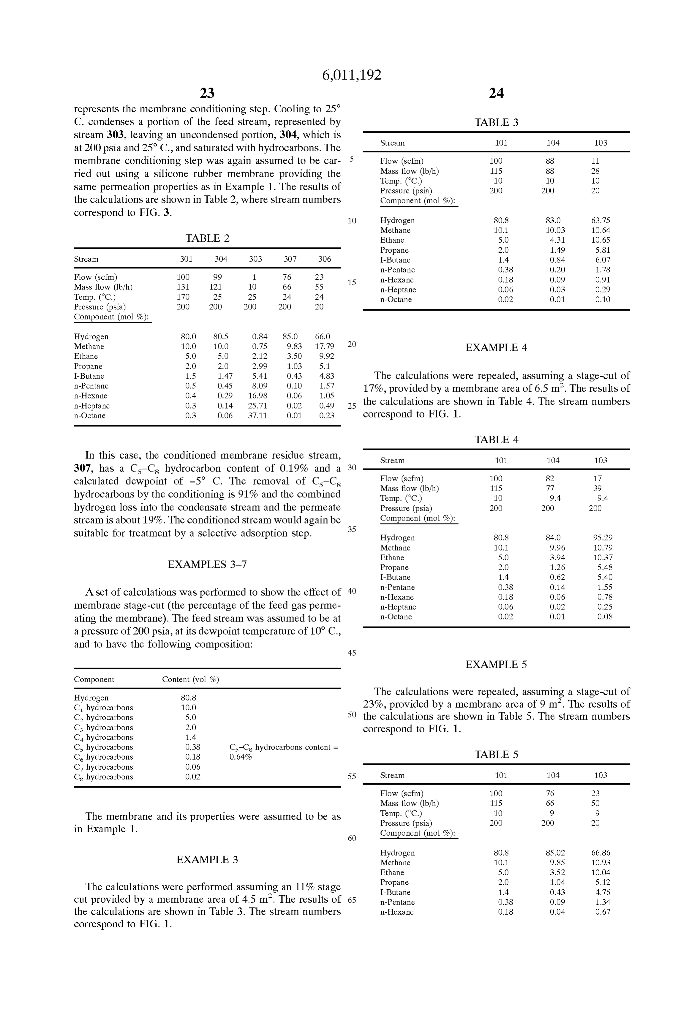
Page 20
TABLE 5-continued
Component Content (vol%)
n-Heptane O.O6 O.O1 O.21 C. hydrocarbons 1.O.O in-Octane O.O2 O.O7 C. hydrocarbons 5.0
--- = less than 0.01 C. hydrocarbons 1.4 Cs hydrocarbons O.38 Cs-C hydrocarbons content =
EXAMPLE 6 1O C, hydrocarbons O.O6
The calculations were repeated, assuming a Stage-cut of 29%, provided by a membrane area of 12 mi. The results of EXAMPLE 8 the calculations are shown in Table 6. The stream numbers correspond to FIG. 1. 15 (not in accordance with the invention)
TABLE 6
The gas was assumed to be introduced at 35 C. into a
System containing hydrogen-Selective membranes, as shown
Stream 101 104 103 by box 405 in FIG. 4. For the purposes of this comparative calculation, the conditioning Step, box 402, was assumed to
Flow (scfm) 1OO 70 29 be absent. The hydrogen-Selective membranes were Mass flow (Ib/h) 115 56 59 assumed to provide the following transmembrane fluxes:
Component (mol%):
Hydrogen 80.8 85.99 68.38 25
Methane 10.1 9.70 11.04 Ethane 0.5 x 10 cm (STP)/cm2 sec cmHg Ethane 5.0 3.10 9.67 Propane 0.3 x 10 cm (STP)/cm2 sec cmHg Propane 2.0 O.83 4.75 I-Butane 0.2 x 10 cm (STP)/cm2 sec cmHg I-Butane 1.4 O.29 4.19 n-Pentane 0.2 x 10 cm (STP)/cm’ sec cmHg n-Pentane O.38 O.O6 1.16 n-Hexane 0.2 x 10 cm (STP)/cm2 sec cmHg n-Hexane O.18 O.O2 0.57 n-Heptane 0.1 x 10 cm (STP)/cm2 sec cmHg n-Heptane O.O6 O.O1 O.18 in-Octane 0.1 x 10 cm (STP)/cm’ sec cmHg
--- = less than 0.01 The results of the calculations are shown in Table 8. The stream numbers correspond to FIG. 4.
TABLE 8
Comparison of Examples 3-6 Stream 404 4O7 4O6
The calculations of Examples 3-6 were compared. Key Flow (scfm) 1OO 27 72 differences are Summarized in Table 7. 40
TABLE 7 Component (mol%):
Membrane Hydrogen Hydrogen Hydrogen 80.8 3O.OO 99.5 Example Area Dewpoint Loss in Residue A Dewpoint Methane 1.O.O 36.60 O.39 No. (m2) (°C.) (%) (%) (°C.) 45 Ethane 5.0 18:47 O.10 Propane 2.O 7.29 O.O3
O 1.O.O O 80.8 O I-Butane 1.4 5.28 O.O2 3 4.5 -2.6 8.9 83.O 12.6 n-Pentane O.38 140 4 65 -9.1 13.6 84.O 19.1 n-Hexane O.18 O.68 5 9 -16.5 19.1 85.O 26.5 n-Heptane O.O6 O.21 6 12 -24.1 24.5 86.O 34.1 50 in-Octane O.O2 O.O7
AS can be seen, there is a tradeoff as expected between dewpoint lowering and hydrogen loSS. However, very low AS hydrogen is Selectively withdrawn into the permeate dewpoints can be reached if required with very modest 55 Stream, the residue stream hydrocarbon content increases membrane areas. The lower the dewpoint, the higher is the Substantially. AS can be seen, the residue stream as it exits level of conditioning and the easier is the Subsequent Selec the modules has a C-C hydrocarbon content of 2.36% and tive adsorption Step. a total hydrocarbon content of 70%. This stream has a dewpoint of 37 C. at 200 psia. Thus, even operating the
EXAMPLES 8-9
membrane separation Step at 35 C., as was assumed, is not
Sufficient to protect the unit from condensation of liquid
A Set of calculations was performed to evaluate the effect hydrocarbons on the membrane surface. To be sure of if gas Streams containing Cs is hydrocarbons are introduced avoiding Such condensation, the feed Stream would have to into hydrogen-Selective membrane Separation units. For the be heated to 40° C. or above.
calculations, the same gas Stream was assumed as in EXAMPLE 9
Examples 3–7, that is, a stream at a pressure of 200 psia, 65 having a dewpoint temperature at 200 psia of 10 C., and The calculations were repeated, this time assuming that having the following composition: the feed Stream is first conditioned by membrane condition
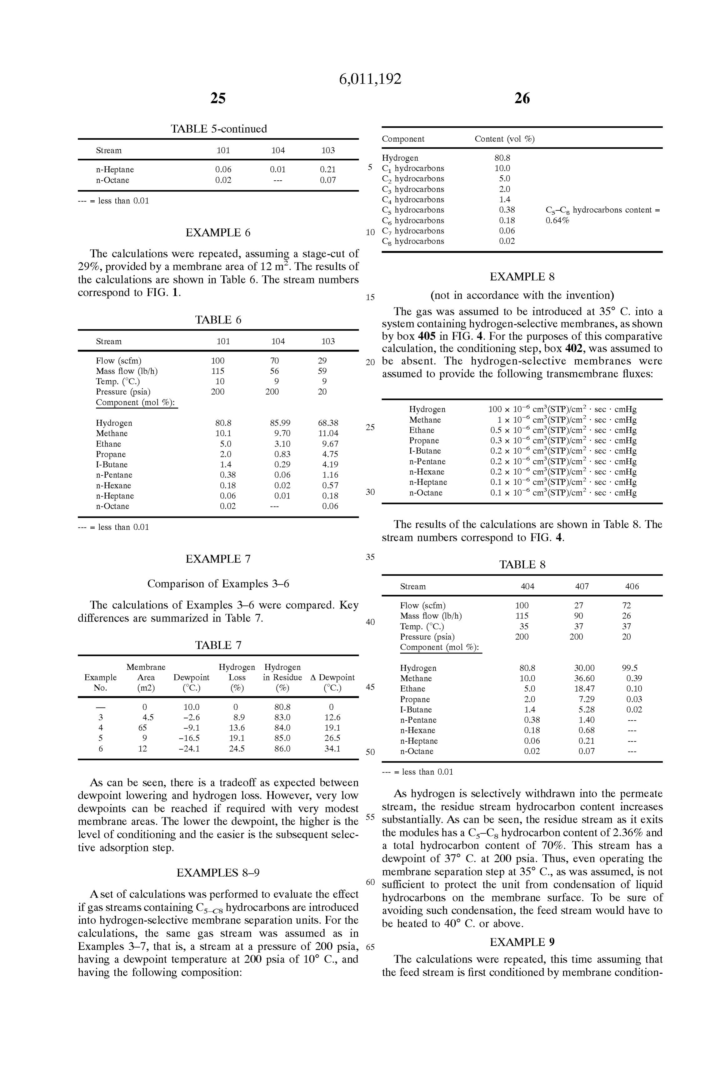
Page 21
ing Step 402. The membranes used for the conditioning Step to 25 C., then passed into the hydrogen/methane separation were assumed to be Silicone rubber membranes providing membranes. The results of the calculations are shown in transmembrane fluxes as in Example 1. In this case, the gas Table 10. The stream numbers correspond to FIG. 5.
was assumed to be introduced into the membrane unit at 10
C. The results of the calculations are shown in Table 9. The 5 TABLE 11 stream numbers correspond to FIG. 4.
Stream SO1 504 503 506 507 510 509
TABLE 9
Flow (scfm) 100 95 5 11 85 60 25
Mass flow 316 259 57 54 205 195 1O
Stream 4O1 403 404 4O7 4O6
Flow (scfm) 1OO 23 76 16 60 Temp. (C.) 50 25 25 24 25 26 26 Mass flow (Ib/h) 115 50 66 45 21 Pressure 2OO 2OO 2OO 2O 2OO 2OO 2O Temp. (C.) 1O 9 1O 11 11 (psia)
Pressure (psia) 2OO 2O 2OO 2OO 2O Component (mol%):
Component (mol%): Hydrogen 45.O 47.11 O.56 24.08 S.O.O2 3O.O1 98.56 15 Methane 25.O 26.09 2.02 18.11 27.10 37.84 1.05
Hydrogen 80.8 66.7 85.O2 3O.OO 99.51
Methane 1.O.O 10.93 9.85 45.76 O.39 Ethane 12.O 1233 5.11 18.47 11.55 16.22 O.22 Ethane 5.0 10.04 3.52 16.62 O.O7 Propane 1.O.O 9.81 13.94 21.65 8.32 11.69 O.13 Propane 2.O 5.12 1.04 4.90 O.O2 I-Butane 3.0 2.71 9.18 9.55 1.84 2.59 O.O3 I-Butane 1.4 4.76 O.43 2.05 O.O1 n-Pentane 2.5 1.50 23.67 6.09 O.92 1.29 OO1 n-Pentane O.38 1.14 O.09 O.43 2O n-Hexane 1.O O31 15.49 1.37 O.18 0.25 --- n-Hexane O.18 O.67 O.04 O.18 n-Heptane 1.O O.12 1946 0.57 O.O7 0.10 --- n-Heptane O.O6 O.21 O.O1 O.OS in-Octane 0.5 O.O2 10.58 O.11 O.O1 0.02 --- in-Octane O O2 O.O7 O.O2 O.O
By conditioning the gas stream, the dewpoint is lowered After cooling to 25 C., the stream obviously has a dewpoint of 25 C. Passage of this saturated stream through to -17 C., a reduction of 27 C. As the gas passes through the hydrogen-Selective the hydrogen-Selective membrane modules, the residue point to 32 C. Thus, the membrane modules raises the dew
Stream C-C hydrocarbon concentration rises to only 0.7% stream would have to be heated and the total hydrocarbon content to 70%. This stream is above this temperature to avoid membrane damage by much lighter than the previous residue Stream in Example 8, 30 hydrocarbon condensation.
and has a dewpoint of 9 C. Although this represents a dewpoint temperature increase of 25 C. compared with the EXAMPLE 11 feed, stream 404, to these modules, it is just below the operating temperature of the System, So no condensation will The calculation of Example 10 was repeated, including
OCC. Obviously, operating at a few degrees higher would 35 the silicone rubber membrane conditioning step as in FIG. 5.
be Safer in a real System. The results of the calculations are shown in Table 11. The
EXAMPLE 10-11 stream numbers correspond to FIG. 5.
A Set of calculations was performed to illustrate the effect TABLE 10 of the conditioning treatment on a fuel gas Stream with a hydrogen content of 45% and a Cs-Cs hydrocarbon content Stream 5O1 507 503 510 509 of 5%. The full gas composition was assumed to be as follows: Flow (scfm) 1OO 95 5 71 24 Mass flow (Ib/h) 316 259 57 250 9
Temp. (C.) 70 25 25 27 27
Pressure (psia) 2OO 2OO 2OO 2OO 2O
Component Content (vol%) 45 Component (mol%):
Hydrogen 45 Hydrogen 45.O 47.11 O.56 3O.OO 98.51 C. hydrocarbons 25 Methane 25.0 26.09 2O2 34.43 1.03 C. hydrocarbons 12 Ethane 12.O 12.33 5.11 16.35 O.24 Cs hydrocarbons 1O Propane 1.O.O 9.81 13.94 13.03 O.16 C. hydrocarbons 3.0 50 I-Butane 3.0 2.71 9.18 3.59 O.04 Cs hydrocarbons 2.5 Cs-C hydrocarbons content = 5% n-Pentane 2.5 1.50 23.67 2.OO O.O1 C. hydrocarbons 1.O n-Hexane 1.O O.31 15.49 O.42 C, hydrocarbons 1.O n-Heptane 1.O O.12 1946 0.17 Cs hydrocarbons 0.5 in-Octane 0.5 O.O2 10.58 O.O3
This gas has a dewpoint at 200 psia of 68°C. The gas was assumed to be at 200 psia and to be subjected to treatment as in FIG. 5, by cooling to 25 C. in step 502, then passing 14The membrane conditioning Step reduces the dewpoint to
C. In this case, passage through the hydrogen/methane to a membrane unit, 505, containing silicone rubber mem branes with permeation properties as in Example 1. Finally, Separation membrane unit raises the dewpoint of the residue the hydrogen/methane Separation was assumed to be carried 60 gas to 21 C. Since this is below the operating temperature out using a conventional hydrogen-Selective membrane hav of the membrane unit, no condensation will occur.
ing permeation properties as in Examples 8–9.
EXAMPLE 10 EXAMPLES 12-13
(not in accordance with the invention) 65 A Set of calculations was performed, based on the same
For this calculation, it was assumed that the membrane assumptions as for Examples 10–11, but this time assuming conditioning Step is absent; that is, the gas is simply cooled a fuel gas Stream with a hydrogen content of only 20%, a
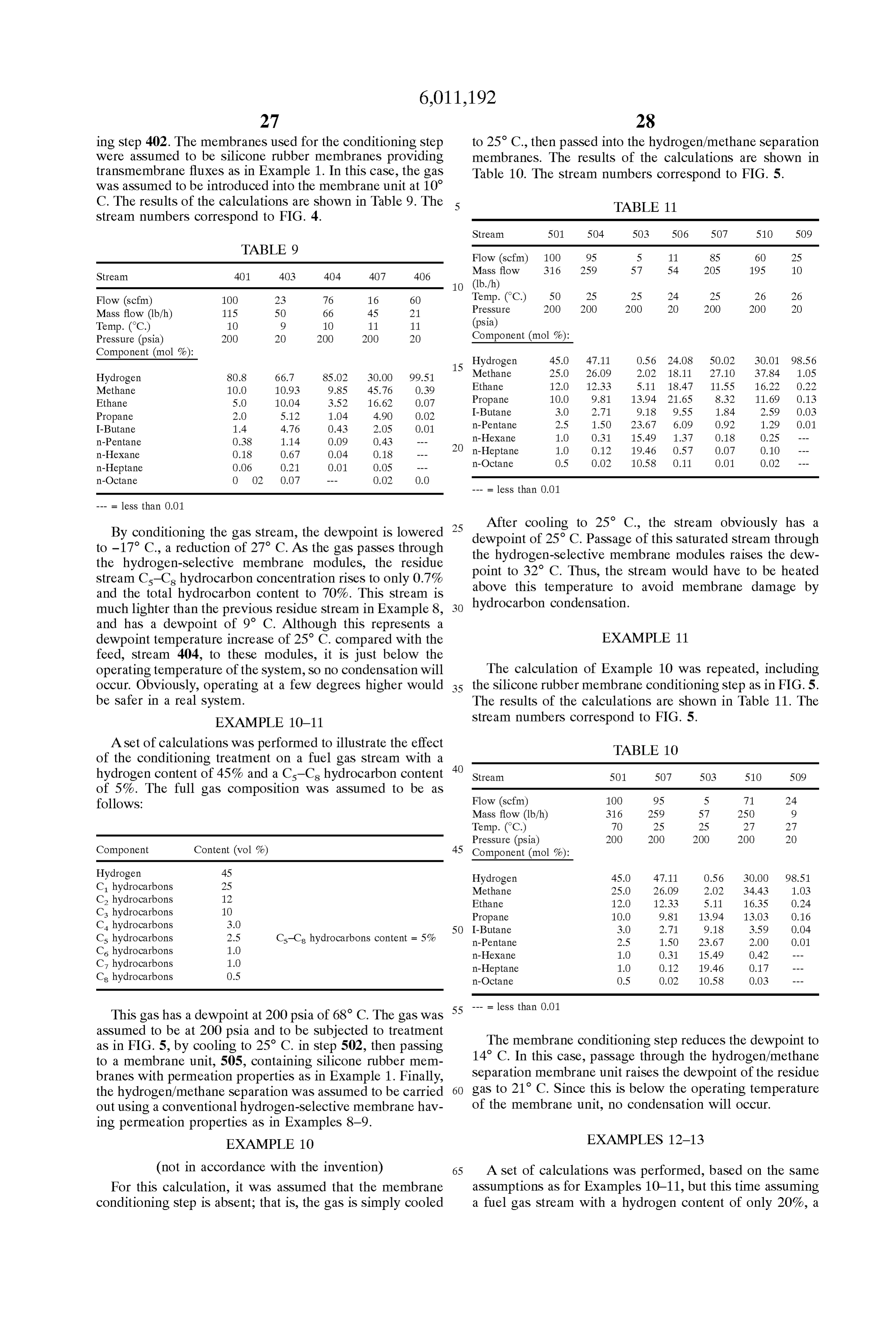
Page 22
propane content of 40%, and a C-C hydrocarbon content of 4%. The full gas composition was assumed to be as TABLE 13-continued follows:
Stream SO1 504 503 506 507 510 509
Pressure 2OO 2OO 2OO 2O 2OO 2OO 2O
Component Content (vol%) (psia)
Component (mol%):
C. hydrocarbons 15 Hydrogen 2O.O 22.84 O.38 7.OS 26.O1 1.O.OO 93.41 C. hydrocarbons 15 Methane 15.O. 16.96 1.49 7.17 18.92 22.73 2.90 C. hydrocarbons 40 Ethane 15.0 16.18 6.84 15.37, 16.34 19.92 1.28 C. hydrocarbons 6.O Propane 4O.O 38.29 51.83 55.56 34.82 42.57 2.18 Cs hydrocarbons 2.O Cs-C hydrocarbons content = 4% I-Butane 6.O 4.74 14.72 1182 3.31 4.05 0.21 C. hydrocarbons 1.O n-Pentane 2.O O.78 10.40 2.32 O.47 O.58 O.O2 C, hydrocarbons 0.5 n-Hexane 1.O 0.17 6.73 O.S6 O.09 O.11 Cs hydrocarbons 0.5 n-Heptane 0.5 O.O3 3.73 0.11 O.O2 0.02 --- 15 in-Octane 0.5 O.O1 3.88 O.O4 O.O1 O.O1
The gas was assumed to be at 200 psia and to be Subjected --- = less than 0.01 to treatment as in FIG. 5, by cooling to 25 C. in step 502, then passing to a membrane unit, 505, containing Silicone EXAMPLE 1.4 rubber membranes with permeation properties as in
Example 1. Finally, the hydrogen/methane Separation was The effect on the dewpoint of a gas of the weight of the assumed to be carried out using a conventional hydrogen individual hydrocarbons that it contains was calculated. The Selective membrane having permeation properties as in first gas composition was assumed to be as follows: Examples 8-9.
EXAMPLE 12 25 Component Content (vol%)
(not in accordance with the invention) C. hydrocarbons 11.0
For this calculation, it was assumed that the membrane Cs hydrocarbons 2.O
conditioning Step is absent; that is, the gas is simply cooled Cs hydrocarbons O.38 to 25 C., then passed into the hydrogen/methane separation C. hydrocarbons O.18 membranes. The results of the calculations are shown in C, hydrocarbons O.O6 Table 12. The stream numbers correspond to FIG. 5. Cs hydrocarbons O.O2
This gas has a dewpoint at 200 psia of 10° C. The gas
Stream 5O1 507 503 510 509 dewpoint was recalculated, first assuming that all the Cs hydrocarbon had been removed, then all the C7 and Cs
Flow (scfm) 1OO 87 13 74 14 hydrocarbons, then all the C, C, and Cs, and So on. The Mass flow (Ib/h) 532 415 117 4O6 1O calculations are Summarized in Table 14. Temp. (C.) 50 25 25 28 28 40
Pressure (psia) 2OO 2OO 2OO 2OO 2O
Component (mol%): TABLE 1.4 Hydrogen 2O.O 22.84 O.38 1O.OO 92.54 Total Methane 15.O 16.96 1.49 19.54 2.94 Hydrocarbon Hydrocarbon New Total Ethane 15.O 16.18 6.84 18.90 1.43 45 Removed Removed Dewpoint A Dewpoint Propane 40.O 38.29 51.83 44.84 2.71 Hydrocarbon (%) (%) (°C) (°C.) I-Butane 6.O 4.74 14.72 5.55 O.34 n-Pentane 2.0 0.78 10.40 O.92 O.O3 Octane O.O2 O.O2 3.0 7.0 n-Hexane 1.O 0.17 6.73 O.2O O.O1 Heptane O.O6 O.08 -6.8 16.8 n-Heptane 0.5 O.O3 3.73 O.04 Hexane O.18 O.26 -22.8 32.8 in-Octane 0.5 O.O1 3.88 O.O1 Pentane O.38 O.64 -42.6 52.6
The Table shows the disproportionate effect of the heavier hydrocarbons on gas dewpoint. By removing as little as
EXAMPLE 13 0.64% of the feed stream in the form of Cs-Cs
The calculation of Example 12 was repeated, including 55 53°hydrocarbons, the dewpoint of the gas is changed by almost
the silicone rubber membrane conditioning step as in FIG. 5. We claim:
The results of the calculations are shown in Table 13. The stream numbers correspond to FIG. 5. 1. A proceSS for treating a gas containing at least hydrogen, methane and a C-C hydrocarbon and having a 60 first dewpoint of at least 10 C. at 200 psia, said process
TABLE 13 comprising a membrane conditioning Step and a hydrogen/
Stream SO1 504 503 506 507 510 509 methane Separation Step;
wherein the membrane conditioning Step comprises
Mass flow S32 415 117 97 319 310 9 removing at least a portion of the Cs-C hydrocarbon (1b/h) 65 from the gas by:
Temp. (C.) 50 25 25 22 25 27 27 (i) passing the gas as a feed stream across the feed side of a polymeric membrane having a feed Side and
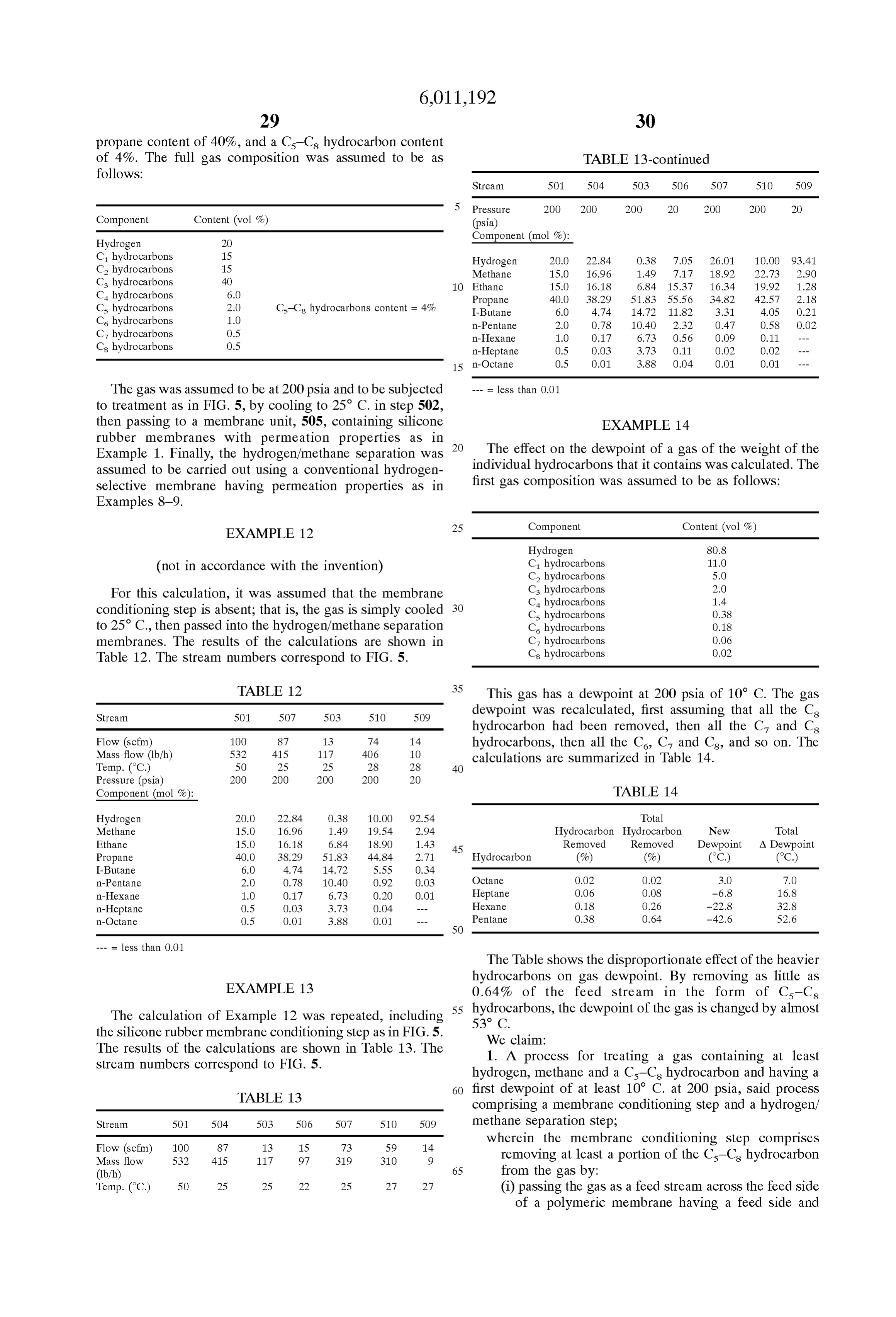
Page 23
permeate Side, and being Selective for the C-Cs 23. A process for treating a gas containing at least hydrocarbon over hydrogen; hydrogen, methane and a C-C hydrocarbon and having a (ii) withdrawing from the permeate side a permeate first dewpoint of at least 10 C. at 200 psia, said process Stream enriched in C-C hydrocarbon compared comprising a membrane conditioning Step and a hydrogen/ with the gas, (iii) withdrawing from the feed side a conditioned methane Separation Step;
residue stream comprising hydrogen and methane wherein the membrane conditioning Step comprises and having a Second dewpoint at 200 psia at least removing at least a portion of the Cs-C hydrocarbon about 10 C. lower than the first dewpoint; from the gas by:
and wherein the hydrogen/methane Separation Step com 1O (i) passing the gas as a feed stream across the feed side prises: of a polymeric membrane having a feed Side and (i) passing the conditioned residue stream to a selective permeate Side, and being Selective for the Cs-Cs adsorption System, thereby Selectively adsorbing hydrocarbon Over hydrogen;
methane from the gas, (ii) withdrawing from the permeate side a permeate (ii) withdrawing a purified hydrogen product stream 15 Stream enriched in Cs-C hydrocarbon compared from the adsorption System;
(iii) desorbing and withdrawing a waste gas Stream with the gas, from the adsorption System. (iii) withdrawing from the feed side a conditioned 2. The process of claim 1, wherein the Selective adsorp residue stream comprising hydrogen and methane tion Step is pressure-Swing adsorption. and having a Second dewpoint at 200 psia at least 3. The process of claim 1, wherein the membrane condi about 10 C. lower than the first dewpoint; tioning Step is carried out using a Silicone rubber membrane. and wherein the hydrogen/methane Separation Step com 4. The process of claim 1, wherein the membrane condi prises a membrane Separation Step, comprising: tioning Step is carried out using a Superglassy membrane. (i) passing the conditioned residue stream as a second 5. The process of claim 1, wherein the membrane condi feed Stream acroSS the Second feed side of a Second tioning Step is carried out using a polyamide-polyether block 25 polymeric membrane having a Second feed side and copolymer membrane.
6. The process of claim 1, wherein the gas is an off-gas a Second permeate Side, and being Selective for from a hydrotreater. hydrogen over hydrocarbons, 7. The process of claim 1, wherein the gas is an off-gas ii) withdrawing from the Second permeate side a puri from a hydrocracker. fied hydrogen product Stream; 8. The process of claim 1, wherein the gas is an off-gas (iii) withdrawing from the Second feed side a residue from a catalytic reformer. waste gas Stream enriched in methane and depleted 9. The process of claim 1, wherein the gas is an off-gas in hydrogen compared with the conditioned gas. from an isomerization process. 24. The process of claim 23, wherein the membrane 10. The process of claim 1, wherein the gas is an off-gas 35 conditioning Step is carried out using a Silicone rubber from a dealkylation process. membrane.
11. The process of claim 1, wherein the gas is an off-gas 25. The process of claim 23, wherein the membrane from a catalytic cracker. conditioning Step is carried out using a Superglassy mem 12. The process of claim 1, wherein the gas is an off-gas brane.
from a coker. 40 26. The process of claim 23, wherein the membrane 13. The process of claim 1, wherein the waste gas Stream conditioning Step is carried out using a polyamide-polyether is used as fuel. block copolymer membrane.
14. The process of claim 1, further comprising passing the 27. The process of claim 23, wherein the second poly gas through an additional treatment Step between the mem meric membrane has a Selectivity for hydrogen over meth brane conditioning Step and the Selective adsorption Step. 45 ane of at least about 10.
15. The process of claim 1, further comprising passing the 28. The process of claim 23, wherein the membrane gas through an additional treatment Step before the mem Separation Step is carried out using a polyimide membrane. brane conditioning Step. 29. The process of claim 23, wherein the gas is an off-gas 16. The process of claim 15, wherein the additional from a hydrotreater.
treatment Step comprises compressing and cooling the gas, 50 30. The process of claim 23, wherein the gas is an off-gas thereby condensing a liquid C-C hydrocarbon fraction, from a hydrocracker.
which is removed from the gas prior to passing the gas 31. The process of claim 23, wherein the gas is an off-gas acroSS the feed Side. from a catalytic reformer.
17. The process of claim 16, wherein the permeate stream 32. The process of claim 23, wherein the gas is an off-gas is recirculated to the additional treatment Step. 55 from an isomerization process.
18. The process of claim 1, wherein the second dewpoint 33. The process of claim 23, wherein the gas is an off-gas is at least about 20° C. lower than the first dewpoint. from a dealkylation process.
19. The process of claim 1, wherein the second dewpoint 34. The process of claim 23, wherein the gas is an off-gas is at least about 30° C. lower than the first dewpoint. from a catalytic cracker.
20. The process of claim 1, wherein the second dewpoint 60 35. The process of claim 23, wherein the gas is an off-gas is at least about 40 C. lower than the first dewpoint. from a coker.
21. The process of claim 1, wherein the membrane 36. The process of claim 23, wherein the waste gas Stream conditioning step removes at least about 80% of the C-C, is used as fuel.
hydrocarbon from the gas. 37. The process of claim 23, further comprising passing 22. The process of claim 1, wherein the membrane 65 the gas through an additional treatment Step between the conditioning step removes at least about 90% of the C-C, membrane conditioning Step and the membrane Separation hydrocarbon from the gas. Step.
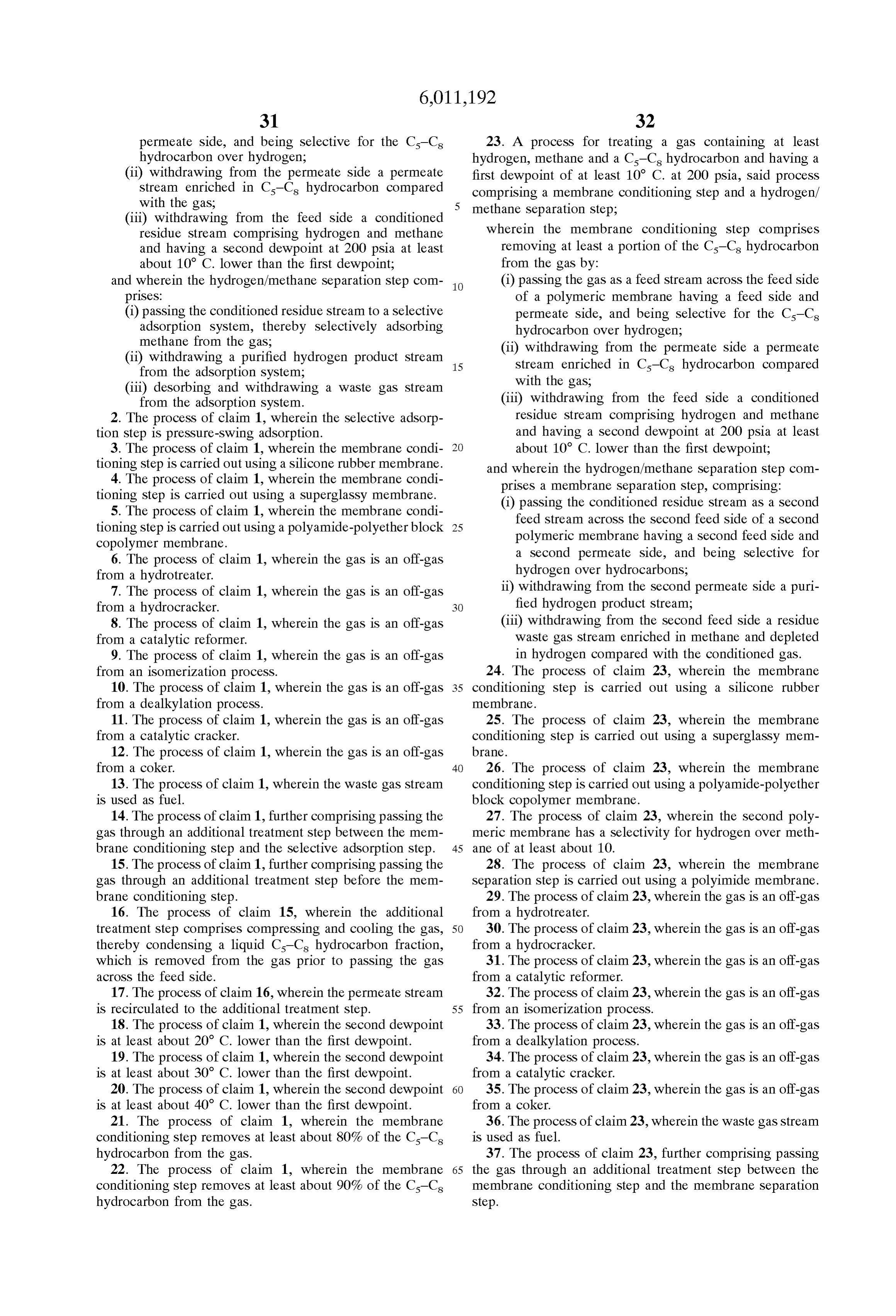
Page 24
38. The process of claim 23, further comprising passing 42. The process of claim 23, wherein the second dewpoint the gas through an additional treatment Step before the is at least about 30° C. lower than the first dewpoint. membrane conditioning Step. 43. The process of claim 23, wherein the second dewpoint 39. The process of claim 38, wherein the additional is at least about 40 C. lower than the first dewpoint. treatment Step comprises compressing and cooling the gas, 44. The process of claim 23, wherein the membrane thereby condensing a liquid C-C hydrocarbon fraction, conditioning Step removes at least about 80% of the Cs-Cs which is removed from the gas prior to passing the gas hydrocarbon from the gas.
acroSS the feed Side. 45. The process of claim 23, wherein the membrane 40. The process of claim 39, wherein the permeate stream conditioning step removes at least about 90% of the C-C, is recirculated to the additional treatment Step. 10 hydrocarbon from the gas.
41. The process of claim 23, wherein the second dewpoint is at least about 20° C. lower than the first dewpoint. k k k k k
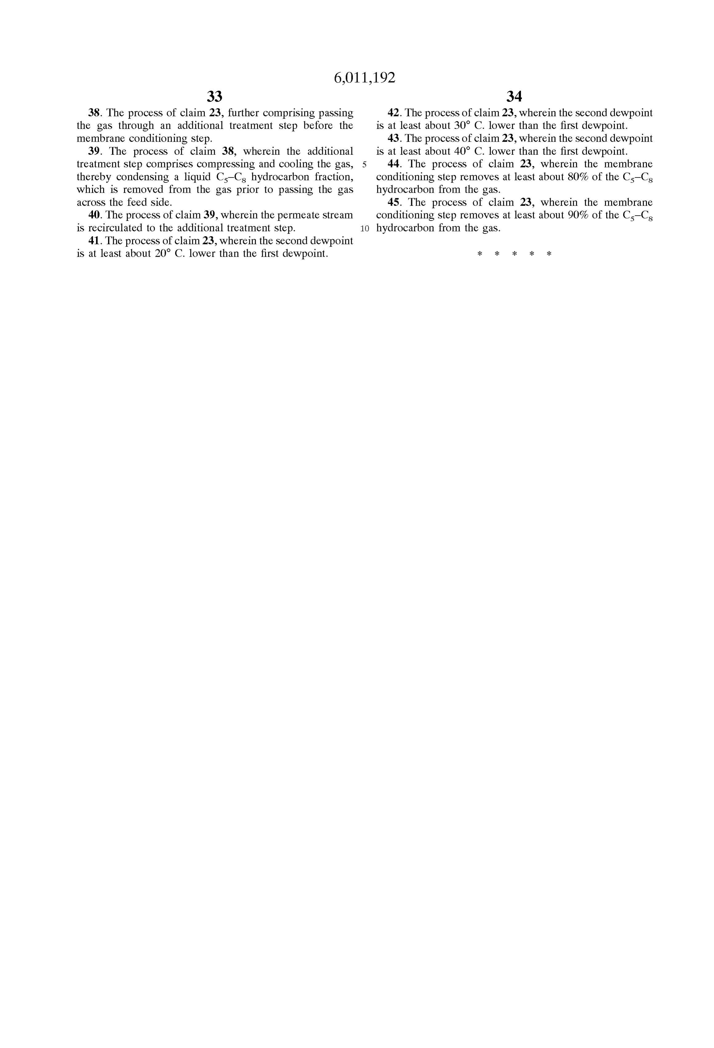
Provenance
- Collection
- Cited prior art
- Original PDF
- patentimages.storage.googleapis.com →
- Filed
- 1998-05-22
- Pages
- 24
- Method
- pdftotext (the PDF's own text layer) + pdftoppm 300dpi page scans
- Source
- Google Patents bibliographic record
- Granted
- 2000-01-04
- Inventors
- Richard W. Baker; Kaaeid A. Lokhandwala; Membrane Technology and Research Inc
- Transcribed from
- patentimages.storage.googleapis.com →