patent · US3694770
Liquid fuel gas dynamic mixing laser
26 September 1972
Page 1 — bibliographic record
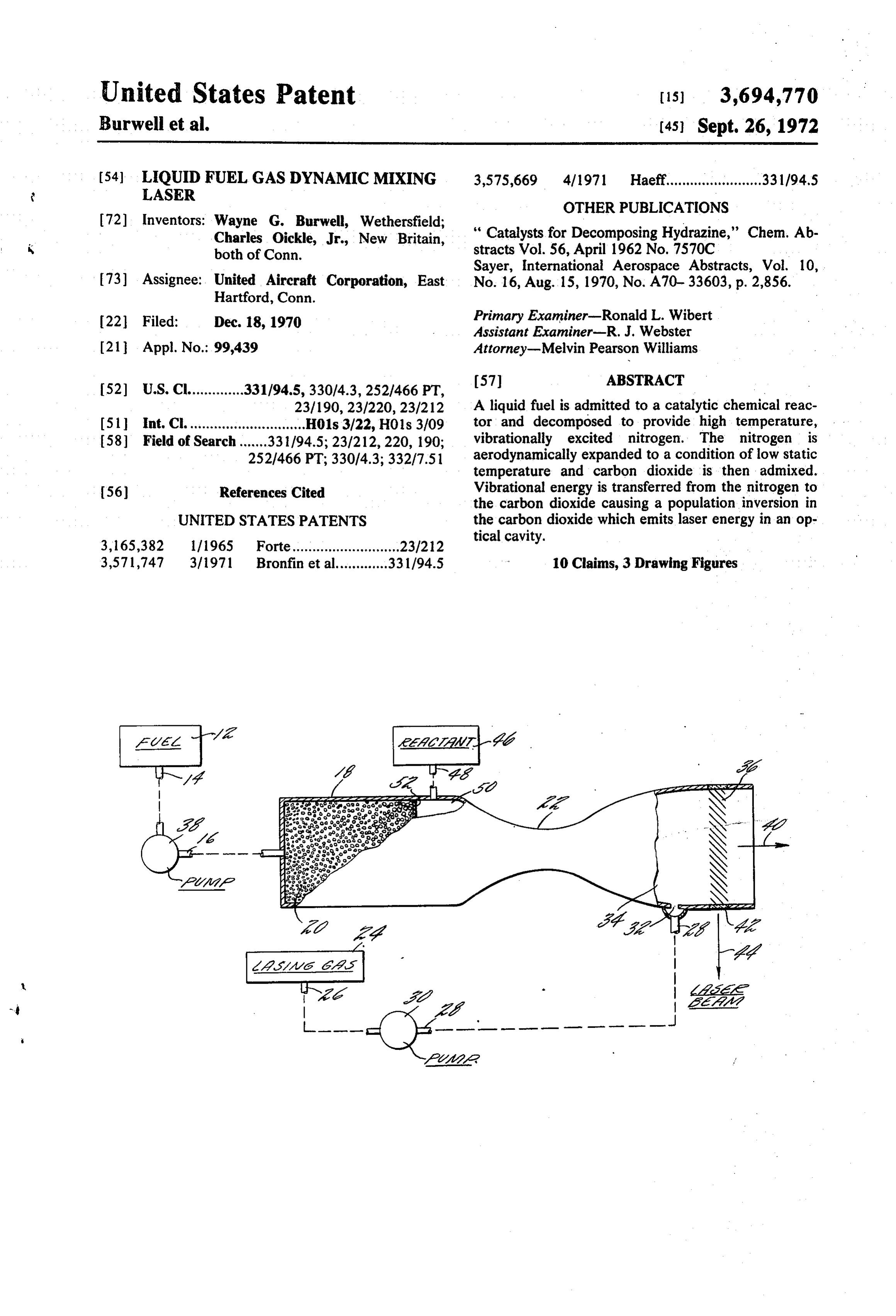
United States Patent is 3,694,770 Burwell et al. (45) Sept. 26, 1972 (54) LIQUID FUEL GAS DYNAMICMXING 3,575,669 4/1971 Haeff........................ 33 1/94.5
LASER
OTHER PUBLICATIONS
72) Inventors: Wayne G. Burwell, Wethersfield;
Charles Oickle, Jr., New Britain, “Catalysts for Decomposing Hydrazine," Chem. Ab both of Conn. stracts Vol. 56, April 1962 No. 7570C
Sayer, International Aerospace Abstracts, Vol. 10, 73) Assignee: United Aircraft Corporation, East No. 16, Aug. 15, 1970, No. A70-33603, p. 2,856. Hartford, Conn.
22 Filed: Dec. 18, 1970 Primary Examiner-Ronald L. Wibert Assistant Examiner-R. J. Webster 21 Appl. No.: 99,439 Attorney-Melvin Pearson Williams
23/190, 23/220, 23/212 A liquid fuel is admitted to a catalytic chemical reac 51 int. Cl.............................. H01s 3/22, HO1s 3/09 tor and decomposed to provide high temperature, 58 Field of Search....... 33 1/94.5; 23/212, 220, 190; vibrationally excited nitrogen. The nitrogen is 252/466 PT; 330/4.3; 332/7.51 aerodynamically expanded to a condition of low static temperature and carbon dioxide is then admixed.
56) References Cited Vibrational energy is transferred from the nitrogen to the carbon dioxide causing a population inversion in
UNITED STATES PATENTS the carbon dioxide which emits laser energy in an op
tical cavity.
3,571,747 3/1971 Bronfin et al............. 33 1/94.5 10 Claims, 3 Drawing Figures
Page 2
Drawing sheet — no readable text.
Page 3
Drawing sheet — no readable text.
Page 4
Drawing sheet — no readable text.
Page 5
LIQUIDFUEFL GAS DYNAMICMXNG LASER ing gas such as nitrogen is vibrationally excited. In BACKGROUND OF THE INVENTION some of the more desirable working systems, a nitrogen 1. Field of invention gas is heated from a thermal source, allowing the molecules to assume an equilibrium distribution ap
This invention relates to lasers and more particularly 5 propriate for the elevated temperature, and distribu to gas dynamic mixing lasers. tion containing a small amount of vibrationally excited 2. Description of the Prior Art nitrogen. The gas molecules are then rearranged in a The continued investigation of laser concepts and nonequilibrium distribution by dynamic means by devices in the past several years has resulted in sophisti passing them through an aerodynamic expansion noz cation of various laser apparatus currently under O zle whereby some of the molecules are transferred to development. The gas dynamic laser which has grown the ground vibrational level and some other molecules out of the initial laser effort, is representative of one of remain in the first vibrational level due to their relative the more sophisticated laser techniques and has the ly long natural relaxation time. The nitrogen which is at potential of providing very high power radiation out supersonic velocity in the nozzle is immediately mixed put, due primarily to the large gas handling capability 15 with carbon dioxide thereby ensuring that the vibra characteristic of such a system and to the large quantity tionally excited nitrogen does not revert to the ground of energy which can be added to the gases flowing in state before colliding with and transferring this vibra such systems. tional energy to the carbon dioxide. The carbon diox Gas laser operation requires that a population inver ide, in turn, has sion be established between upper energy levels and cavity while stillsufficient velocity to reach the optical vibrationally excited. The ability to lower energy levels of the lasing medium. In a sim provide vibrationally excited nitrogen plified functional description of the carbon dioxide manner makes possible large populationin inversions a gas dynamic and nitrogen laser, carbon dioxide molecules are excited in turn the lasing of carbon dioxide.
from the ground vibrational energy level (000) to an 25 The gas dynamic laser is a relatively inefficient upper vibrational energy level (001) - the upper las device, having a thermal energy to laser energy overall ing level - by collision with vibrationally (V-1) conversion efficiency of approximately three fourths of excited nitrogen and then stimulated to emit elec 1 percent; however, if the temperature of the thermally tromagnetic radiation. The emission causes the carbon dioxide to assume an intermediate vibrational energy 30 excited gases can be raised sufficiently, the overall con version efficiency can be increased by a factor of up to level (100) - the lower lasing level - for a period of approximately 4. Conversion efficiencies much higher time before returning to the ground (000) level, than this are unlikely in a simple system because of the passing through a non-laser emitting (010) level in the inherent characteristic of the various energy transfer process. Successfully maintaining the population inver processes involved in the production of laser energy sion necessary to laser output requires controlling the 35 with a hot gas in the gas dynamic process. In a typical rates at which the carbon dioxide molecules pass current system, the extraction efficiency of an optical through all the various energy levels, and unless the cavity is approximately 50 percent, the quantum effi 010level can receive all the 100-010 transitions, the number of carbon dioxide molecules producing laser ciency for the transition of carbon dioxide gas from the energy (undergoing the 001-100 transition) is 40 001 level to the 100 level is 41 percent and the tem reduced. peratures of combustion raise about 3 percent of the The non-emitting 010 level which exists between the population of the exciting nitrogen gas to the first lower lasing (100) level and the ground level has a rela vibrational V-1 level, resulting in an overall thermal tively long natural relaxation time and presents a natu to-laser energy conversion efficiency no higher than ral bottleneck in the overall carbon dioxide energy 45 about three fourths of 1 percent.
exchange process. However, certain relaxant gases Mixtures of carbon dioxide and nitrogen are desira such as water vapor, helium or hydrogen readily couple ble for the system described due primarily to the physi with carbon dioxide at the 010 level producing an al cal characteristics of these gases. For a laser applica ternate energy release mechanism sufficient to avoid tion, carbon dioxide is generally provided by the com the described bottlenecking in the energy exchange SO bustion of a limited number of sources, preferably car processes. bon monoxide or cyanogen, and subsequent admixing The 001 energy level of a carbon dioxide molecule is of nitrogen is required to provide the correct gas mix preferentially pumped by collision with vibrationally ture prior to expansion through the nozzle. Laser excited nitrogen, due to a naturally occuring match of beams of substantial power at a wavelength of approxi energy levels between these two gases. In addition to 5 5 mately 10.6 microns have been produced with the type the matched energy level characteristic, nitrogen has a gas dynamic laser described, however, the gas-handling relatively long lifetime in the first vibrational (VFl) equipment required is large and a troublesome disad level (compared to a short lifetime of the carbon diox vantage. Gas dynamic lasers inherently consume a ide at the corresponding 001 level), and when vibra large amount of gas and therefore require a substantial tionally excited nitrogen is mixed with carbon dioxide, 60 array of high pressure gas bottles, gages and associated the nitrogen preferentially transfers its vibrational equipment to produce a laser beam for any sustained energy to carbon dioxide molecules upon collision duration. A solution to the current problem of bulki therewith, the nitrogen reverting to the ground (VF0) ness would appear to be the combustion in air of a car state and the carbon dioxide assuming an excited or 65 bon containing liquid fuel. Theoretically, the only con lasable state having a relatively short lifetime. sumable required in such a system would be the liquid The gas dynamic laser terminology refers to an ex fuel, the air being freely available at the operation site; citation or pumping technique whereby tee laser pump the carbon in the fuel could provide the necessary car
Page 6
bon dioxide by combustion with the oxygen component vide an energy exchange mechanism beneficial to the of air, and the necessary nitrogen would be una lasing of carbon dioxide.
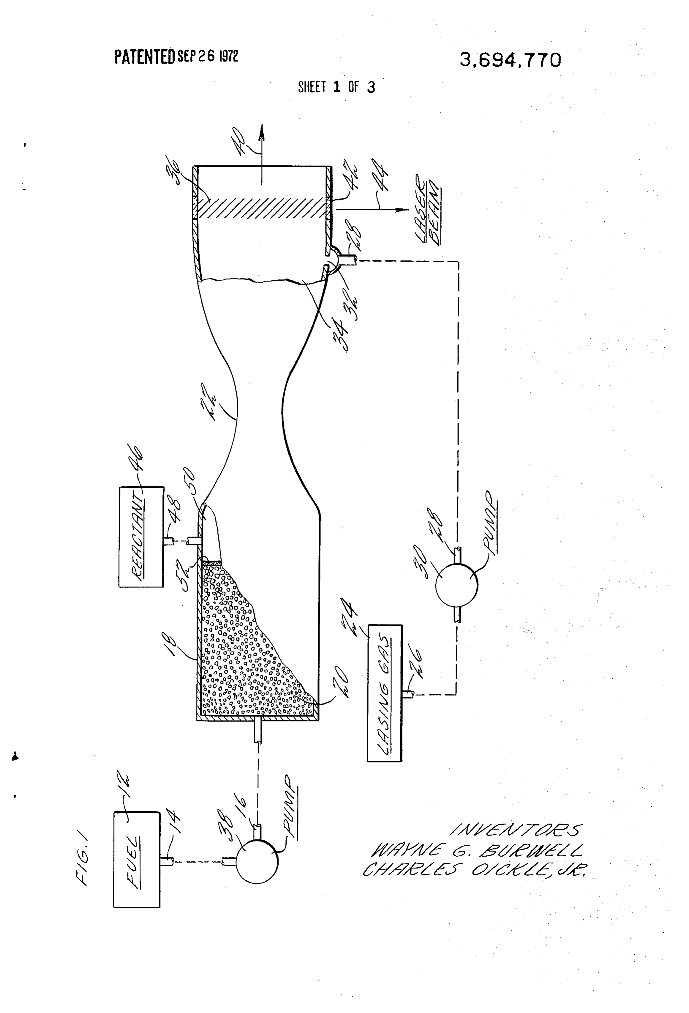
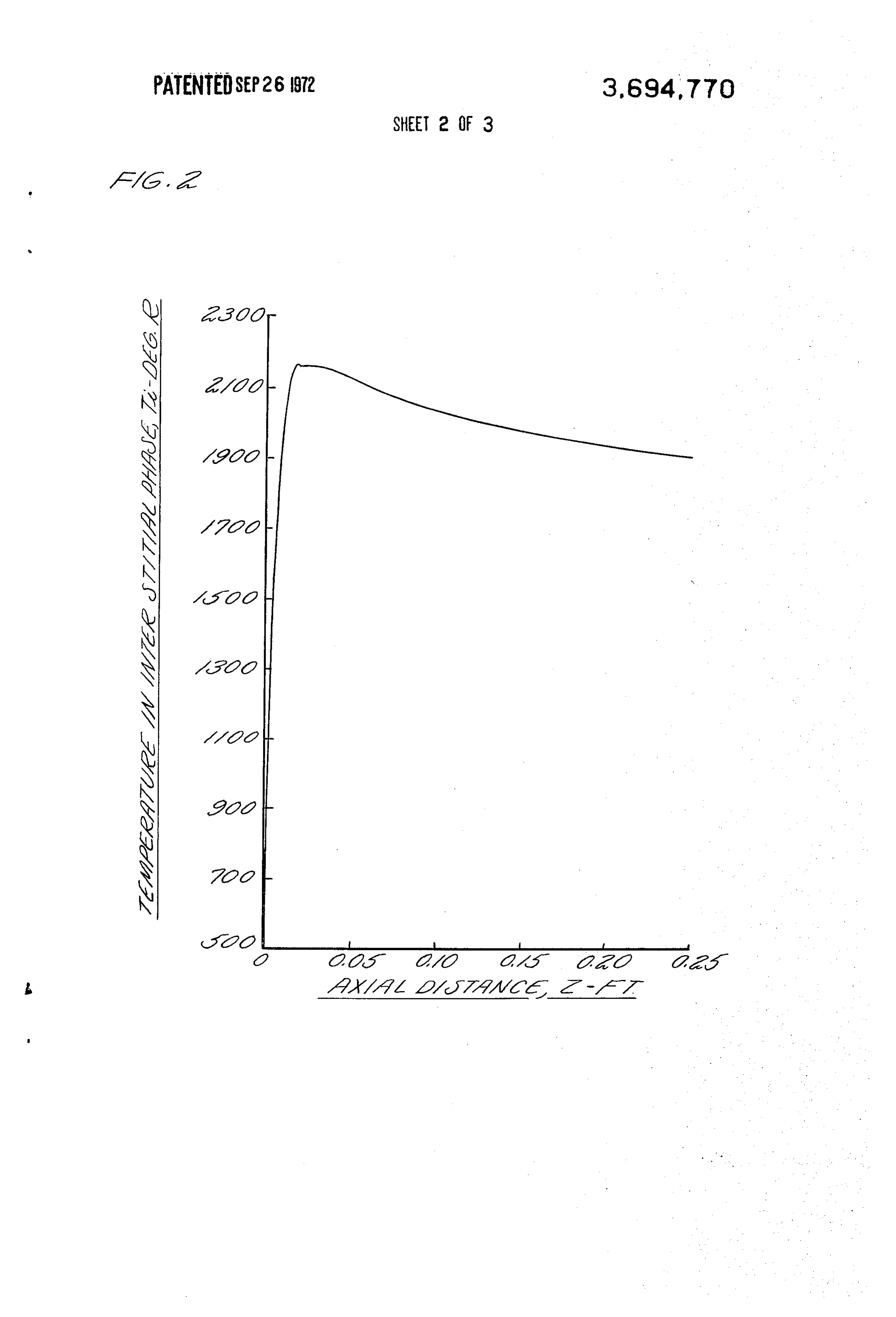
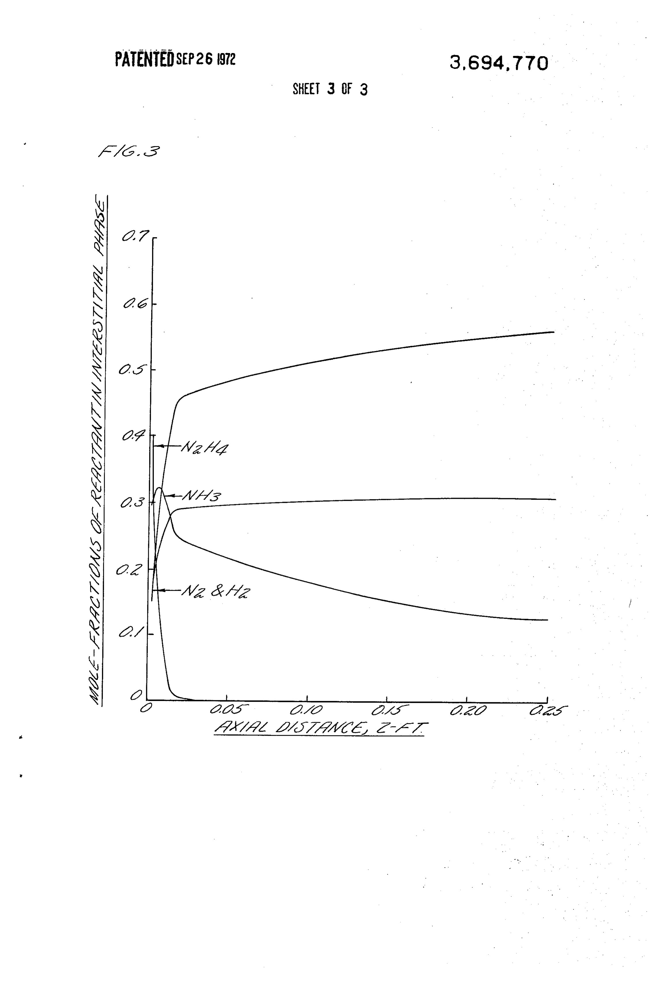
voidably present due to its natural occurrence as the predominant component of air. However, the com BRIEF DESCRIPTION OF THE DRAWING bustion of any fuel with air introduces a number of un FIG. 1 is a simplified, sectioned, plan view of one em desired by-products in amounts sufficient to compete bodiment of a gas dynamic mixing laser having a cata with the gas molecule energy transfer required to lytic reactor in accordance with the present invention; produce a lasing of the gas mixture. Interference of FIG. 2 is a graph illustrating the effect of catalytic fered by these contaminants reduces the conversion ef. 10 reactor length on the temperature of the decomposed ficiency of available energy to laser energy. In addition, products;
the nitrogen-carbon dioxide molecule ratio is not op FIG. 3 is a graph illustrating the effect of catalytic timum further reducing the overall performance of reactor length on the mole fraction of decomposition such a system; even if a preferred fuel such as carbon products.
monoxide or cyanogen is burned with air, the amount 15 of nitrogen present in the combustion products if below DESCRIPTION OF THE PREFERRED optimum, resulting in a substantial reduction in the EMBODIMENT amount of lasing energy extractible from such a system. Referring to FIG. 1, a liquid hydronitrogen fuel In order to circumvent the suggested inefficient source 12 communicates by suitable means, such as the systems, carbon monoxide and cyanogen gaseous fuels 20 connecting pipes 14 and 16 with a chemical catalytic have been combusted with pure oxygen to provide a reactor 18 filled with a packed bed 20 comprised of highly energized source of carbon dioxide or carbon porous alumina substrate which has been impregnated dioxide-nitrogen mixture, and subsequently a con with noble metal. A two dimensional aerodynamic noz trolled quantity of nitrogen is admixed such that the zle 22 is attached directly to the reactor 18 in commu total gas expanded in the gas dynamic laser nozzle is 25 nication with a source 24 of carbon dioxide by suitable one of the proper proportions to produce the maximum means such as pipes 26 and 28. The carbon dioxide power laser output beam. However, an optimize high may be stored as a high pressure gas in which case there output power laser system requires a nitrogen-to-car is no need for pump 30. The carbon dioxide is admitted bon dioxide molecule ratio of approximately 6 to 1 and to the nozzle through a slot 32 located in the nozzle it is apparent that a system, particularly a carbon 30 wall 34 at a location along the nozzle wall where full ex monoxide fuel system, relying on the combustion of a pansion of the gases passing therethrough has not yet fuel in oxygen, requires that an enormous amount of occurred. An optical cavity 36 is attached to the low bottled nitrogen accompany the system and be availa pressure side of the nozzle 22 as used herein optical ble during operation. Further, the combustibles typi cavity is defined as means for providing amplification cally are exhausted to atmosphere after lasing and a 35 of electromagnetic radiation by stimulated emission of new charge of gases is required if subsequent lasing ac radiation from a medium having a suitable population tion is desired. inversion of energy levels.
SUMMARY OF THE INVENTION In the operation of the present invention, the liquid 40 fuel hydrazine is removed from the fuel source 12
A principal object of this invention is the production through the pipe 14 by pump 38 and transported of high power laser energy utilizing nitrogen gas through the pipe 6 to the chemical reactor 18. In produced by the catalytic decomposition of a liquid steady state operation, the hydrazine interacts with the fuel. catalytic packed bed 20 thereby releasing heat while According to the present invention, a mixture of high 45 forming nitrogen, hydrogen and ammonia gases. These temperature nitrogen and other gases is produced by hot gases are lowered in pressure and temperature by the decomposition of a liquid hydronitrogen fuel in a an expansion across the nozzle 22, and carbon dioxide catalytic reactor, the gases being expanded in a super from the source 24 is admixed with the nitrogen and sonic nozzle and admixed with cooler carbon dioxide to hydrogen in the nozzle, the carbon dioxide entering the provide a population inversion of vibrational energy 50 nozzle 22 through slot 32. The gas admixture passes levels in the carbon dioxide capable of being stimulated through the optical cavity 36 and discharges as exhaust to emit laser radiation. gas 40, laser energy having been released by the admix The present invention eliminates the voluminous ture in the optical cavity and removed therefrom storage and handling equipment required for the gase through the laser coupling device 42 as laser beam 44. ous fuel and energizing gas in a gas dynamic laser; the 55 A reactants source 46 communicates by suitable means necessity of storing toxic and difficult to handle feed such as a connecting pipe 48 with a reaction chamber gases is avoided also. An additional advantage of this 50 which is located between the packed bed 20 and the invention is that the energy required to raise the tem aerodynamic nozzle 22. A porous grid 52 separates the perature of the nitrogen is inherently provided by the packed bed from the reaction chamber. catalytic decomposition process of the liquid fuel 60 Hydrazine is a preferred fuel, although other providing the nitrogen gas. The decomposition of a hydronitrogen compounds are suitable. A group of hydronitrogen compound produces molecular fuels comprising hydrogen azide (NH), hydrazine hydrogen, as well as the nitrogen gas, providing still azide (NHs) and ammonium azide (NH) is suitable other advantages; these gases can be chemically 65 for use in this invention since they provide large reacted with a reactant, releasing heat and raising the amounts of nitrogen at even higher temperature than temperature of the nitrogen above the temperature of does hydrazine. An additional group of fuels compris decomposition. Further, the reaction products can pro ing diimide (N2H2), triazine (NH3), diiminohydrazine
Page 7
S 6
(NH2), bisdiazoamine (NH), hexazodiazene (NH), expansion, the higher the potential conversion efficien heptazodiazene (NHs) and octazotriene (NH) is also cy of the system.
suitable for use with this invention since each fuel in In the present invention with hydrazine fuel, am this group provides a larger proportion of nitrogen at monia and hydrogen product gases are present during higher temperature than does hydrazine. the nitrogen expansion, however, they do not interact A reduction of one hundred degrees Rankine in the with the nitrogen in exactly the same manner as does temperature of the nitrogen gas leaving the reactor has carbon dioxide. Actually, these product gases can pro been found to produce a one half percent reduction in vide certain advantages to the mixing laser concept. the number of vibrationally excited nitrogen gas 10 For example, they can be reacted in the chamber 50 molecules. Under the best catalytic conditions, the with a reagent such as hydrogen peroxide, chlorine products of hydrazine are formed as a gas at a peak trifluoride or chlorine pentafluoride, thereby decreas temperature of about 2,100 R. This temperature is ing the amount of product gas and increasing the tem ample to ensure a laser device of acceptable output perature of the nitrogen stream. Also, some of the reac power, however, if the temperature were to be reduced 15 tions produce water molecules which promote relaxa significantly, the practicality of the system would be tion of the 010 (bottleneck) level of carbon dioxide. questionable; the temperature condition below which The presence of some water in the lasing gas mixture is this system will produce essentially no useful power is advantageous, however, too much water is undesirable. about 1,200 R. If the catalytic reactor is forced, that is, There is no sharp upper limit on the tolerable amount the reactor length is increased to ensure complete con 20 of water, but if the lasing gases comprise more than version of the input fuel to the end products theoreti about 10 percent by volume of water vapor, the system cally attainable, the temperature of the gases would be power output decreases appreciably. On the other lower than the peak temperature, perhaps as much as hand, ammonia in particular, accepts vibrational ener 300R lower. gy from the carbon dioxide and can put a constraint on There are distinct advantages to the operation of a 25 the overall system design. The presence of ammonia in gas dynamic mixing laser as contrasted with a gas amounts of up to about one percent of the total gas dynamic laser. For example, in the former, the gas ex flow through the nozzle is acceptable; in higher propor panded is largely nitrogen having a relatively long tions, the ammonia begins to significantly reduce the relaxation time for the vibrationally excited (V-1) output power from the lasing cavity. In this invention, level, and the population inversion established during 30 the amount of ammonia in the gas can exceed one per expansion can therefore be maintained over relatively cent, however, the energy loss mechanism described is long linear distances downstream of the nozzle for a avoided in much the same manner as the gas dynamic given gas velocity. In the gas dynamic laser, however, laser system avoids loss of the vibrational energy in the the gas expanded is a mixture of nitrogen and carbon carbon dioxide molecules. The optical cavity is placed dioxide, the latter having a relatively short relaxation 35 at a short distance from the nozzle exit such that the time for the vibrationally excited (V-1) level and ammonia does not deplete a substantial amount of the therefore requiring that the optical cavity be physically excited carbon dioxide molecules before said near the expansion nozzle. Unless the transit time for molecules have entered the cavity region. The azide the expanded gases from the nozzle to the optical cavi 40 fuels produce relatively less ammonia at elevated tem ty is less than the decay time for the 100 level carbon perature than hydrazine fuel and they are desirable in dioxide, the population inversion is lost before the gas this respect.
enters the optical cavity and the depleted gas does not The design of the chemical reactor wherein the cata lase. Also, in the mixing configuration the carbon diox lytic decomposition of the hydrazine takes place ide is injected at a relatively cold temperature, resulting 45 represents an engineering compromise. The break in only a minimal population of the carbon dioxide down of hydrazine theoretically produces pure lower energy levels before lasing activity is initiated. hydrogen and nitrogen; as a practical matter, ammonia Mixing the carbon dioxide at a temperature of approxi is also formed since the reaction does not go to comple mately 550 R avoids having the lower vibrational tion, and the amount of ammonia so formed can be levels of the carbon dioxide occupied due to the ther 50 substantial if the catalytic reactor is overly short. The mal activity of the gas. Perhaps more importantly, the independent variable in the reactor design is the length mixing laser inherently is a higher efficiency device; in of the catalytic bed through which the hydrazine fuel is a non-mixing system, all the gases are premixed prior to allowed to pass in the process of decomposing into its expansion and the pumping gas, typically nitrogen, is constituent elements; dependent variables are the tem subjected to energy loss mechanisms by collision with 55 perature of the gases produced and the mole fraction of the other gases present. These collisions result in a the gases hydrogen, nitrogen, ammonia, and hydrazine. decrease in overall conversion efficiency since energy A curve of the temperature of the decomposed gases which would otherwise be available for lasing is trans as a function of the catalytic reactor length is shown in ferred from the nitrogen by the collision processes be 60 FIG. 2. From these data, temperature considerations fore expansion occurs. There is an optimum tempera indicate that a relatively short reactor approximately ture above which the amount of energy which is being three tenths of an inch in length would be preferred lost by the collision processes is greater than the since an effluent gas having a temperature of approxi amount of additional vibrational energy which is being mately 2,150 R would be provided. However, from transferred to the nitrogen pumping gas. In a mixing 65 FIG. 3 it is apparent that a reactor of this length would system, however, the pumping gas is heated while still produce an effluent gas mixture having an undesirably segregated from the remaining gases and theoretically high ammonia mole fraction. The data of FIG. 3 in the higher the temperature of the pumping gas prior to dicates further that as the reactor length is increased,
Page 8
the ammonia content in the gases is decreased. There to the optical cavity region where the laser energy can fore, from a gas composition point of view, a reactor be extracted.
much longer than three tenths of an inch is desired. As The injection of the carbon dioxide gas should not a practical matter, the reactor length is established by occur until the static temperature (the actual tempera selecting a maximum temperature which does not allow ture of the gas not considering the kinetic energy of the the reactor to yield an unacceptably high mole fraction molecule) of the nitrogen is at a level (approximately of ammonia. ambient temperature) that ensures the carbon dioxide An additional consideration in the reactor design, is will not be thermally heated to the 100 level. As a prac the pressure drop introduced by the catalytic bed in the flowing hydrazine stream. The longer the bed becomes O tical matter, the static temperature is about the same as the carbon dioxide gas injection temperature. The sub for a given set of conditions, the greater is the pump ject is discussed more fully in Bronfin, B. R., Boedeker, work required to overcome this pressure drop. The L. R., and Cheyer, J. R., Thermal Laser Excitation by porous bed, comprised of a commercial catalyst ob Mixing in a Highly Convective Flow, Applied Physics tained under the name of Shell 405, has been found to 15 Letters, Vol. 16, No. 5, March 1, 1970, p. 214. perform satisfactorily in the reactor. This catalyst Although the invention has been shown and comes in a variety of sizes and shapes; cylindrical pel described with respect to preferred embodiments lets one eighth inch in both diameter and length have thereof, it should be understood by those skilled in the been found to be a practical selection. When the art that the foregoing and various changes and omis catalyst size becomes smaller than one eighth inch, the 20 sions in the form and detail thereof may be made fuel is decomposed very efficiently but there is a rela therein without departing from the spirit and the scope tively large pressure drop across the packed bed of the of the invention.
reactor; alternatively, larger size pellets tend to result Having thus described typical embodiments of our in inefficient use of the fuel and a low pressure drop. invention, that which we claim as new and desire to The composition and method of manufacturing the 25 secure by Letters Patent of the United States is: Shell 405 catalyst is proprietary, however, the material 2. The method of providing laser energy in a gas is substantially a porous alumina substrate covered by dynamic mixing laser utilizing nitrogen as an excitation metal which is essentially iridium. Any of the noble gas and carbon dioxide as a lasing gas, comprising the metals should function as an effective catalyst. steps of:
The nozzle design required in the operation of this 30 decomposing a liquid hydronitrogen fuel by an ex invention must meet a few simple criteria. It has been othermic reaction in a catalytic chemical reaction found, for example, that the length of the nozzle must chamber to form a gas mixture including nitrogen be such that, having considered the velocity of the gas molecules which are at thermal equilibrium; gases being expanded through the nozzle, the relaxa 35 rapidly expanding the gas mixture in an aerodynamic tion time of the vibrational mode for the gas must be nozzle from a static temperature not less than greater than the residence time of the gas in the nozzle. about 1,200 R to a static temperature of approxi Failure to satisfy this criterion allows the gas to relax mately 550 R to establish a nonequilibrium condi before exiting the nozzle and since the relaxed or de tion in the vibrational energy levels of the nitrogen excited gas is unable to selectively pump the lasing gas, gaS;
no lasing action occurs. This subject is discussed more 40 admixing carbon dioxide which is at a temperature fully in Anderson, John D. Jr., Time-Dependent Analy no greater than about 550 R to the expanded gas sis of Population Inversions in an Expanding Gas, The mixture in the nozzle to form a gas admixture in Physics of Fluids, Vol. 13, No. 8, August 1970, p. which energy contained in the vibrational energy 1983. 45 levels of the nitrogen is transferred by collision It has been found also that if the nozzle expansion processes to the carbon dioxide, to establish a surfaces are not continued (in the direction of the gas population inversion in the vibrational energy flow) beyond the point at which the carbon dioxide las levels of the carbon dioxide molecules; ing gas is injected, admixing carbon dioxide to the flow passing the gas admixture through an optical ing gas stream causes the stream temperature to rise; 50 chamber stimulating emission of radiation from without expansion after injection, some of the carbon said inolecules while in said chamber; dioxide becomes thermally excited into the 010 level, exhausting the gas admixture from the optical an undesirable condition for lasing of the carbon diox chamber.
ide gas. 2. The method according to claim a further compris A third limitation upon the nozzle design requires a 55 ing, between the step of admixing carbon dioxide and short physical separation between the point of admix the step of passing the gas admixture through an optical ing and the optical cavity. When ambient temperature chamber, the additional step of:
carbon dioxide is admixed with a flowing stream of expanding the gas admixture in a nozzle sufficiently nitrogen having a population inversion consisting of to ensure a static temperature of the gases exiting vibrationally excited molecules, the carbon dioxide un 60 the nozzle of approximately 550 R. dergoes a rapid energy exchange with the nitrogen, the 3. The method according to claim 2 wherein the fuel carbon dioxide being selectively pumped into the upper is selected from the group consisting of hydrazine, lasing 001 level. The lifetime for carbon dioxide at this hydrogen azide, hydrazine azide, ammonium azide, dii energy condition is very short and unless a short nozzle 65 mide, triazine, diminohydrazine, bisdiazoamine, hex is used together with very high velocity gas streams azodiazene, heptazodiazene and octazotriene. through the nozzle, much of the 001 carbon dioxide gas 4. The method according to claim 2 wherein the fuel relaxes before this gas is passed from the mixing region is hydrazine.
Page 9
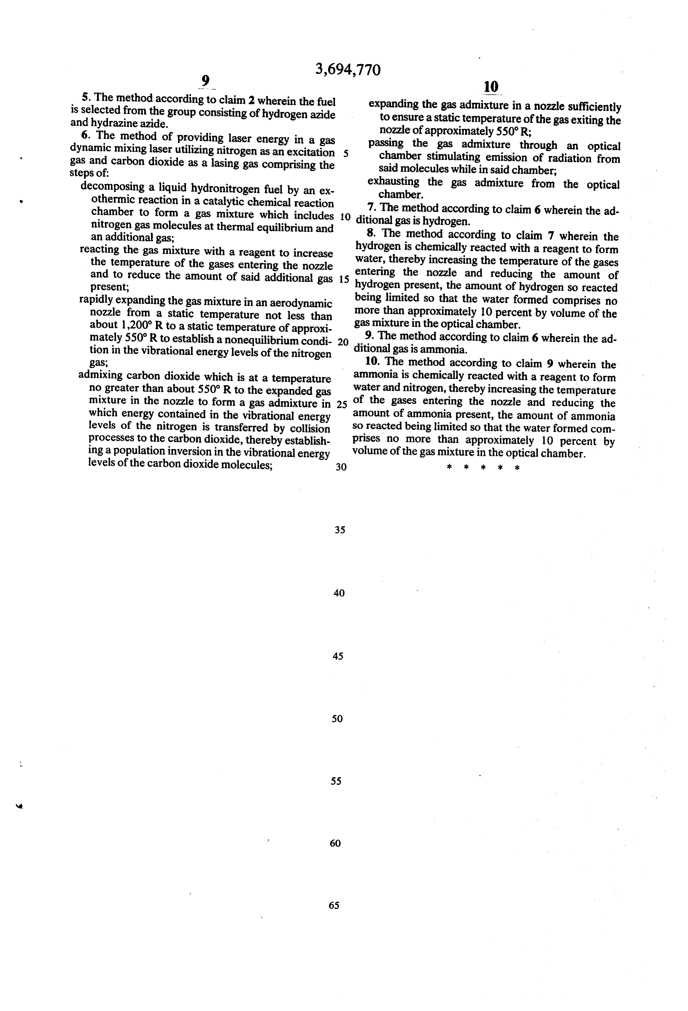
5. The method according to claim 2 wherein the fuel
is selected from the group consisting of hydrogen azide expanding the gas admixture in a nozzle sufficiently and hydrazine azide. to ensure a static temperature of the gas exiting the 6. The method of providing laser energy in a gas nozzle of approximately 550'R; dynamic mixing laser utilizing nitrogen as an excitation 5 passing the gas admixture through an optical gas and carbon dioxide as a lasing gas comprising the chamber stimulating emission of radiation from steps of: said molecules while in said chamber; decomposing a liquid hydronitrogen fuel by an ex exhausting the gas admixture from the optical chamber.
othermic reaction in a catalytic chemical reaction 7. The method according to claim 6 wherein the ad chamber to form a gas mixture which includes O ditional gas is hydrogen.
nitrogen gas molecules at thermal equilibrium and an additional gas; 8. The method according to claim 7 wherein the hydrogen is chemically reacted with a reagent to form reacting the gas mixture with a reagent to increase water, the temperature of the gases entering the nozzle thereby increasing the temperature of the gases and to reduce the amount of said additional gas 15 hydrogen the present;
entering nozzle and reducing the amount of present, the amount of hydrogen so reacted rapidly expanding the gas mixture in an aerodynamic being limited so that the water formed comprises no nozzle from a static temperature not less than more than approximately 10 percent by volume of the about 1,200 R to a static temperature of approxi gas mixture in the optical chamber. mately 550 R to establish a nonequilibrium condi 20 9. The method according to claim 6 wherein the ad tion in the vibrational energy levels of the nitrogen ditional gas is ammonia.
gas 10. The method according to claim 9 wherein the admixing carbon dioxide which is at a temperature ammonia is chemically reacted with a reagent to form no greater than about 550 R to the expanded gas water and nitrogen, thereby increasing the temperature mixture in the nozzle to form a gas admixture in 25 of the gases entering the nozzle and reducing the which energy contained in the vibrational energy amount of ammonia present, the amount of ammonia levels of the nitrogen is transferred by collision so reacted being limited so that the water formed com processes to the carbon dioxide, thereby establish prises no more than approximately 10 percent by ing a population inversion in the vibrational energy volume of the gas mixture in the optical chamber. levels of the carbon dioxide molecules; 30 2k xk k k sk
Page 10
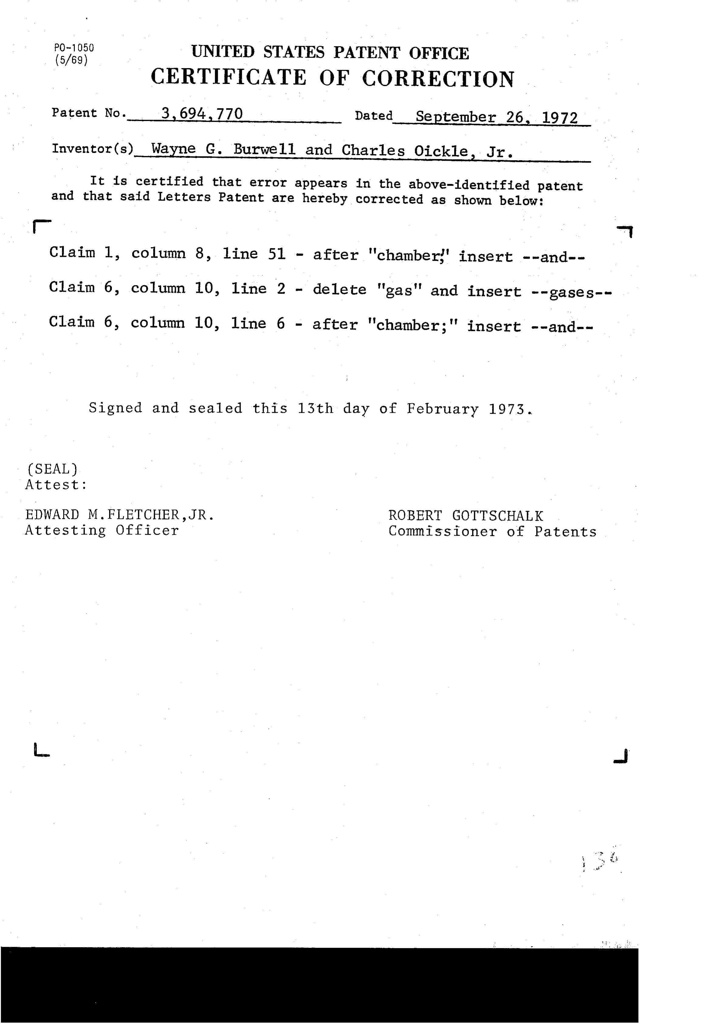
(5/69) UNITED STATES PATENT OFFICE
5/69 CERTIFICATE OF CORRECTION
Patent No. 3, 694,770 Dated September 26, 1972 Inventor(s). Wayne G. Burwell and Charles Oickle, Jr. It is certified that error appears in the above-identified patent and that said Letters Patent are hereby corrected as shown below: - - Claim 1, column 8, line 51 - after 'chamber' insert --and-- Claim 6, column 10, 1ine 2 - delete "gas" and insert --gases-- Claim 6, column 10, 1ine 6 - after 'chamber;' insert --and--
Signed and sealed this 13th day of February 1973.
(SEAL)
At test :
EDWARD M. FLETCHER, JR. ROBERT GOTTSCHALK Attesting Officer Commissioner of Patents
Page 11
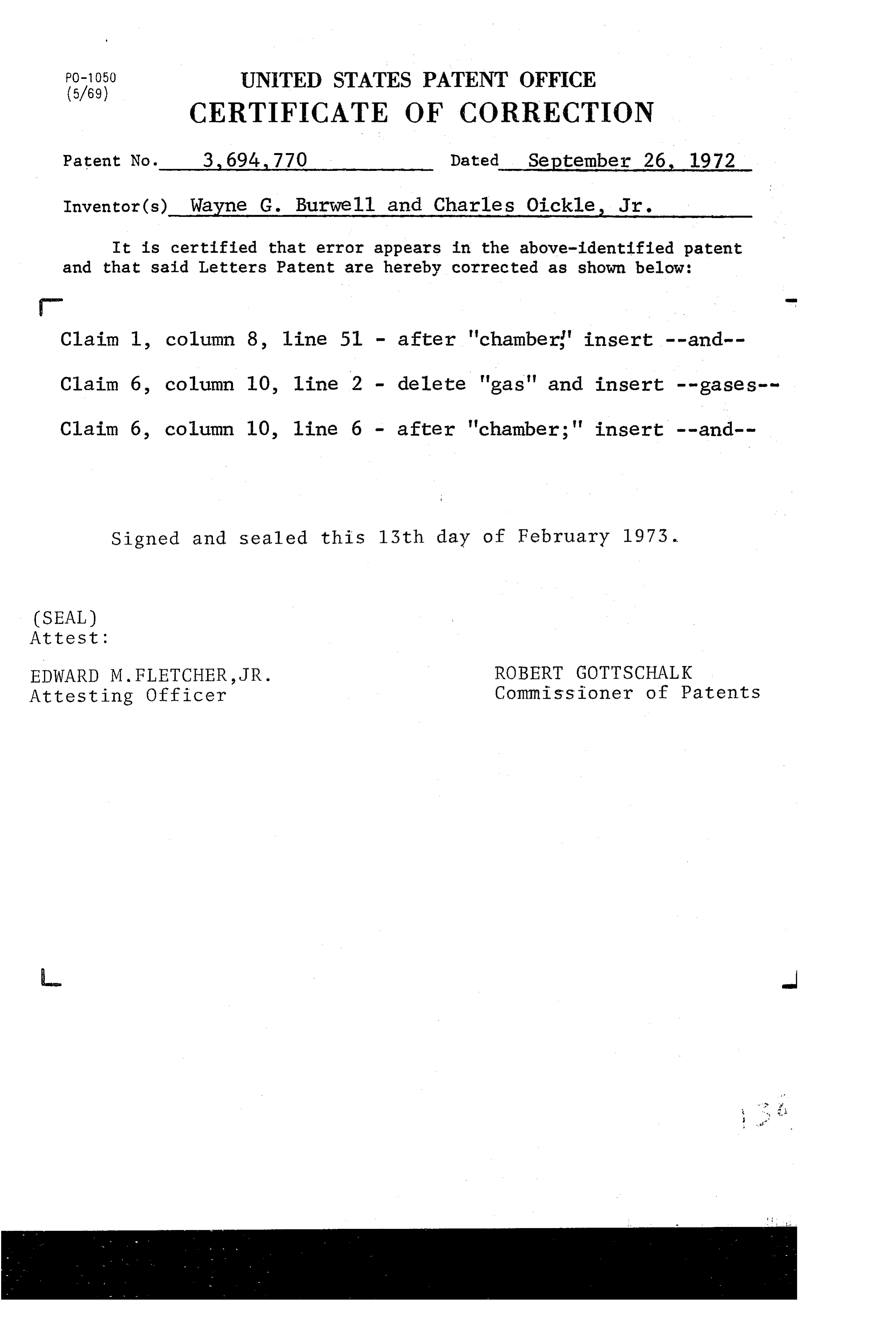
PO-1050 UNITED STATES PATENT OFFICE
" CERTIFICATE OF CORRECTION
Patent No. 3. 694,770 Dated September 26, 1972 Inventor(s) Wayne G. Burwell and Charles Oickle, Jr. It is certified that error appears in the above-identified patent and that said Letters Patent are hereby corrected as shown below: - m Claim 1, column 8, 1ine 51 - after 'chamberg" insert --and-- Claim 6, column 10, 1ine 2 - delete 'gas' and insert --gases-- Claim 6, column 10, line 6 - after 'chamber;' insert --and--
Signed and sealed this 13th day of February 1973.
(SEAL)
At test :
EDWARD M. FLETCHER, JR. ROBERT GOTTSCHALK Attesting Officer Commissioner of Patents
Provenance
- Collection
- Cited prior art
- Original PDF
- patentimages.storage.googleapis.com →
- Filed
- 1970-12-18
- Pages
- 11
- Method
- pdftotext (the PDF's own text layer) + pdftoppm 300dpi page scans
- Source
- Google Patents bibliographic record
- Granted
- 1972-09-26
- Inventors
- Wayne G Burwell; Charles Oickle Jr; United Aircraft Corp
- Transcribed from
- patentimages.storage.googleapis.com →