patent · US5752157
Liquid fuel reforming apparatus
12 May 1998
Page 1 — bibliographic record
United States Patent (19) 11 Patent Number: 5,752,157 Yamashita et al. 45 Date of Patent: May 12, 1998
54) LIQUID FUEL REFORMINGAPPARATUS 4,716.024 12/1987 Pera ................................... 422/186.0 5.236,670 8/1993 Iwata 422.86.04 75 Inventors: Takeshi Yamashita, Nakatsugawa; Hiro 5,348.050 9/1994 Ashton . ... 1377827 Yamashita, 4580-59, Naegi, Gifu, both 5,368,705 1 1/1994 Cassidy ................................... 204/136 of Japan Primary Examiner-Charles T. Jordan
Assistant Examiner-John R. Hardee 73) Assignees: Centerfield Kabushiki Kaisha, Aichi; Attorney, Agent, or Firm-Koda and Androlia Hiro Yamashita, Gifu, both of Japan
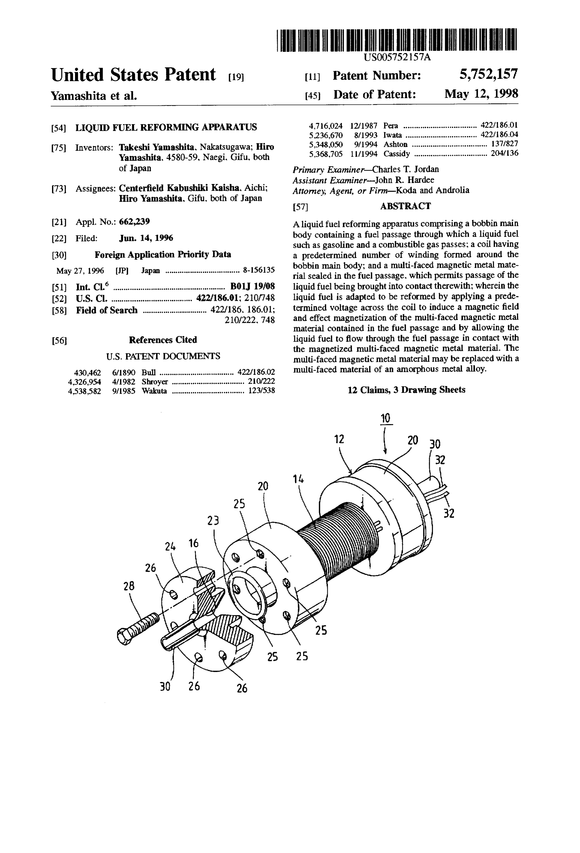
21 Appl. No.: 662,239 A liquid fuel reforming apparatus comprising a bobbin main (22 Filed: Jun. 14, 1996 body containing a fuel passage through which a liquid fuel such as gasoline and a combustible gas passes; a coil having (30) Foreign Application Priority Data a predetermined number of winding formed around the May 27, 1996 JP Japan .................................... 8-156135 bobbin main body; and a multi-faced magnetic metal mate rial sealed in the fuel passage. which permits passage of the (51) Int. Cl. ... B01J 19/08 liquid fuel being brought into contact therewith: wherein the 52 U.S. Cl. ..................................... 422/186.01: 210/748 liquid fuel is adapted to be reformed by applying a prede 58) Field of Search ............................... 422/186, 186.01; termined voltage across the coil to induce a magnetic field 210/222, 748 and effect magnetization of the multi-faced magnetic metal material contained in the fuel passage and by allowing the 56 References Cited liquid fuel to flow through the fuel passage in contact with the magnetized multi-faced magnetic metal material. The
430,462 6/1890 Bull .................................... 422/18602 multi-faced material of an amorphous metal alloy. 4.326,954 4/1982 Shroyer ................................... 20/222 4.533,582 9/1985 Wakuta ................................... 123/538 12 Claims, 3 Drawing Sheets
Page 2
Drawing sheet — no readable text.
Page 3
Drawing sheet — no readable text.
Page 4
Drawing sheet — no readable text.
Page 5
LIQUID FUEL REFORMINGAPPARATUS invention, the liquid fuel reforming apparatus according to BACKGROUND OF THE INVENTION the present invention comprises a bobbin main body con taining a fuel passage through which a liquid fuel such as 1. Field of the Invention gasoline and a combustible gas passes; a coil having a The present invention relates to a liquid fuel reforming 5 predetermined number of winding formed around the bobbin apparatus, more particularly to a liquid fuel reforming main body; and a multi-faced magnetic metal material apparatus which can reform, for example, liquid fuels to be sealed in the fuel passage, which permits passage of the employed in internal combustion engines such as gasoline liquid fuel being brought into contact therewith; wherein the engine, combustion apparatuses for boilers, etc. or gaseous liquid fuel is adapted to be reformed by applying a prede fuels such as liquefied natural gases (LNG) so as to improve 10 termined voltage across the coil to induce a magnetic field combustion efficiency in the internal combustion engines and effect magnetization of the multi-faced magnetic metal and combustion apparatuses, as well as, to reduce nitrogen material contained in the fuel passage and by allowing the compounds (NOx) contained in the exhaust gases. liquid fuel to flow through the fuel passage in contact with 2. Description of the Related Art the magnetized multi-faced magnetic metal material. Various means for achieving substantially complete com 15 Likewise, in order to overcome the problems inherent in bustion of gasoline in a gasoline engine loaded on an the prior art and suitably attain the intended objective of the automobile have so far been proposed. These means are present invention, the liquid fuel reforming apparatus intended to improve fuel consumption efficiency and to according to the present invention comprises a bobbin main decrease nitrogen compounds (NOx) contained in the body containing a fuel passage through which a liquid fuel exhaust gases. For example, there is known a fuel consump such as gasoline and a combustible gas passes; a coil having tion improving apparatus consisting of a plurality of perma a predetermined number of winding formed around the nent magnet pieces arranged annularly at predetermined bobbin main body; and a multi-faced amorphous metal intervals around a fuel feeding pipe through which gasoline material sealed in the fuel passage, which permits passage of is force-fed from a tank by a pump to a carburetor. Accord the liquid fuel being brought into contact therewith; wherein ing to this fuel consumption improving apparatus, the 25 the liquid fuel is adapted to be reformed by applying a molecular arrangement of gasoline flowing through the pipe predetermined voltage across the coil to induce a magnetic is modified by the magnetic field induced by these perma field and effect magnetization of the multi-faced amorphous nent magnet pieces to effect so-called activation of the metal material contained in the fuel passage and by allowing gasoline whereby to achieve improvement of fuel consump the liquid fuel to flow through the fuel passage in contact tion. Meanwhile, there are some other means appearing on 30 with the magnetized multi-faced amorphous metal material. the market advertising that they can give excellent ignition sparking and can improve gasoline combustion efficiency by BRIEF DESCRIPTION OF THE DRAWINGS merely winding a special band around the joint between a The features of the present invention that are believed to high-tension cord extended from an ignition coil and an be novel are set forth with particularity in the appended engine ignition plug. 35
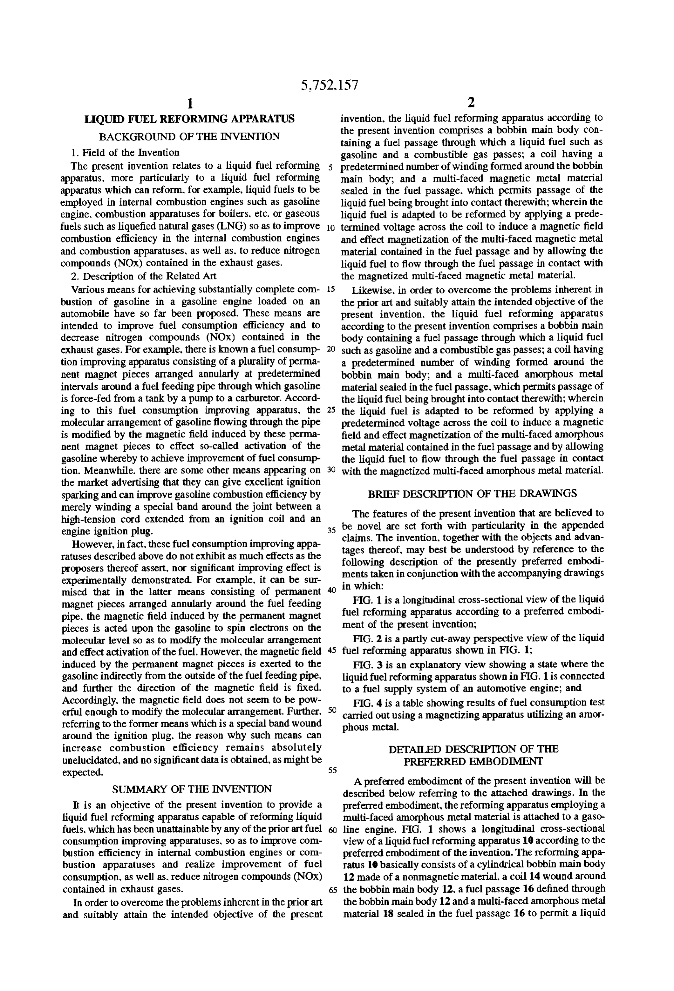
However, in fact, these fuel consumption improving appa claims. The invention, together with the objects and advan ratuses described above do not exhibit as much effects as the tages thereof, may best be understood by reference to the proposers thereof assert, nor significant improving effect is following description of the presently preferred embodi experimentally demonstrated. For example, it can be sur ments taken in conjunction with the accompanying drawings in which:
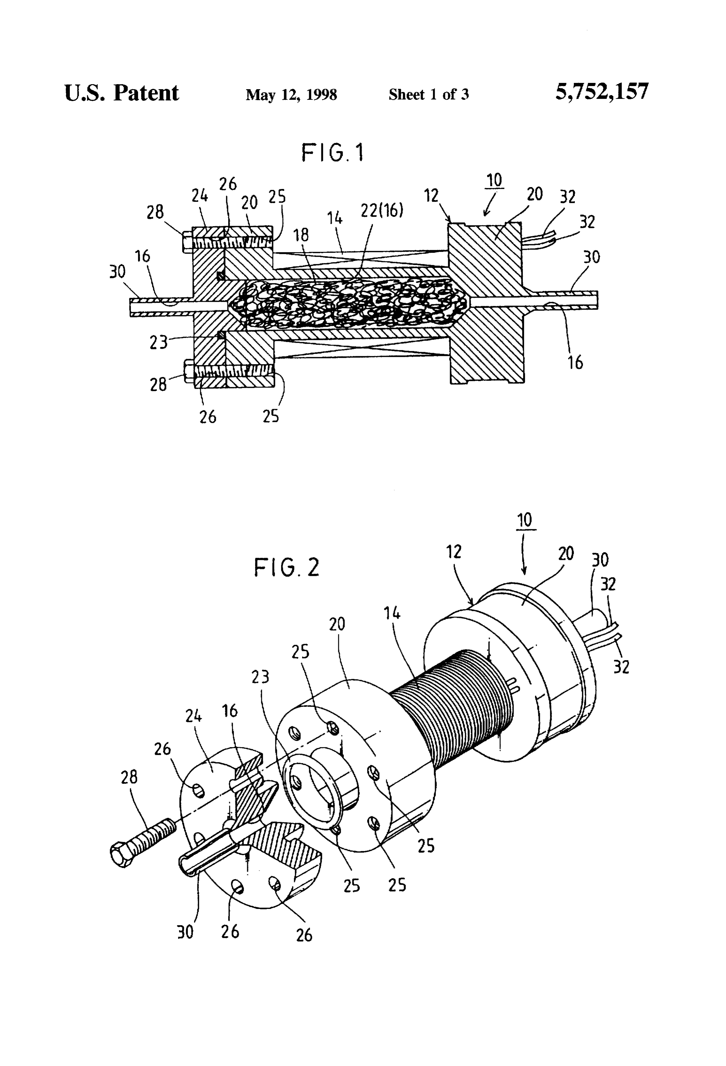
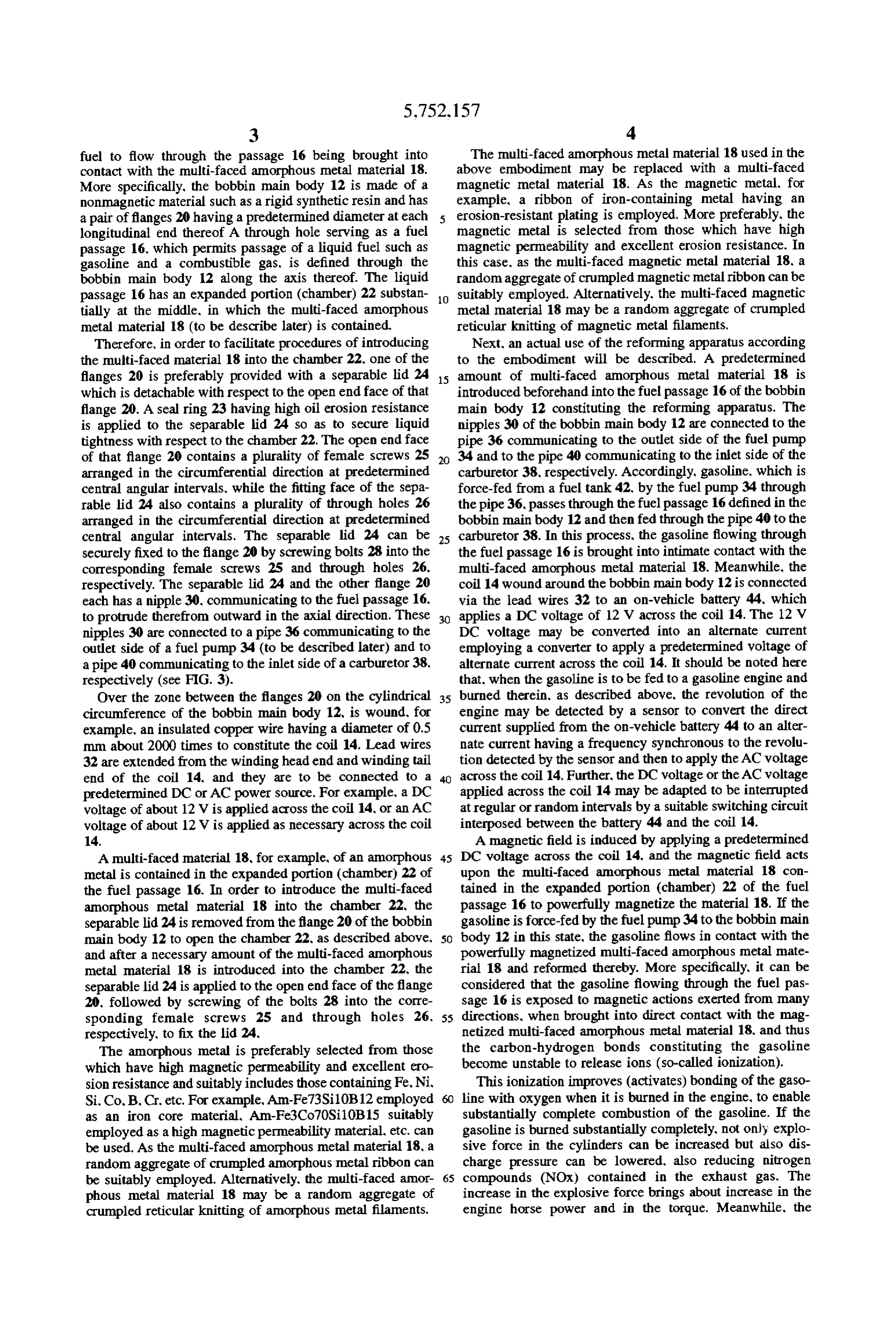
mised that in the latter means consisting of permanent magnet pieces arranged annularly around the fuel feeding FIG. 1 is a longitudinal cross-sectional view of the liquid pipe, the magnetic field induced by the permanent magnet fuel reforming apparatus according to a preferred embodi pieces is acted upon the gasoline to spin electrons on the ment of the present invention;
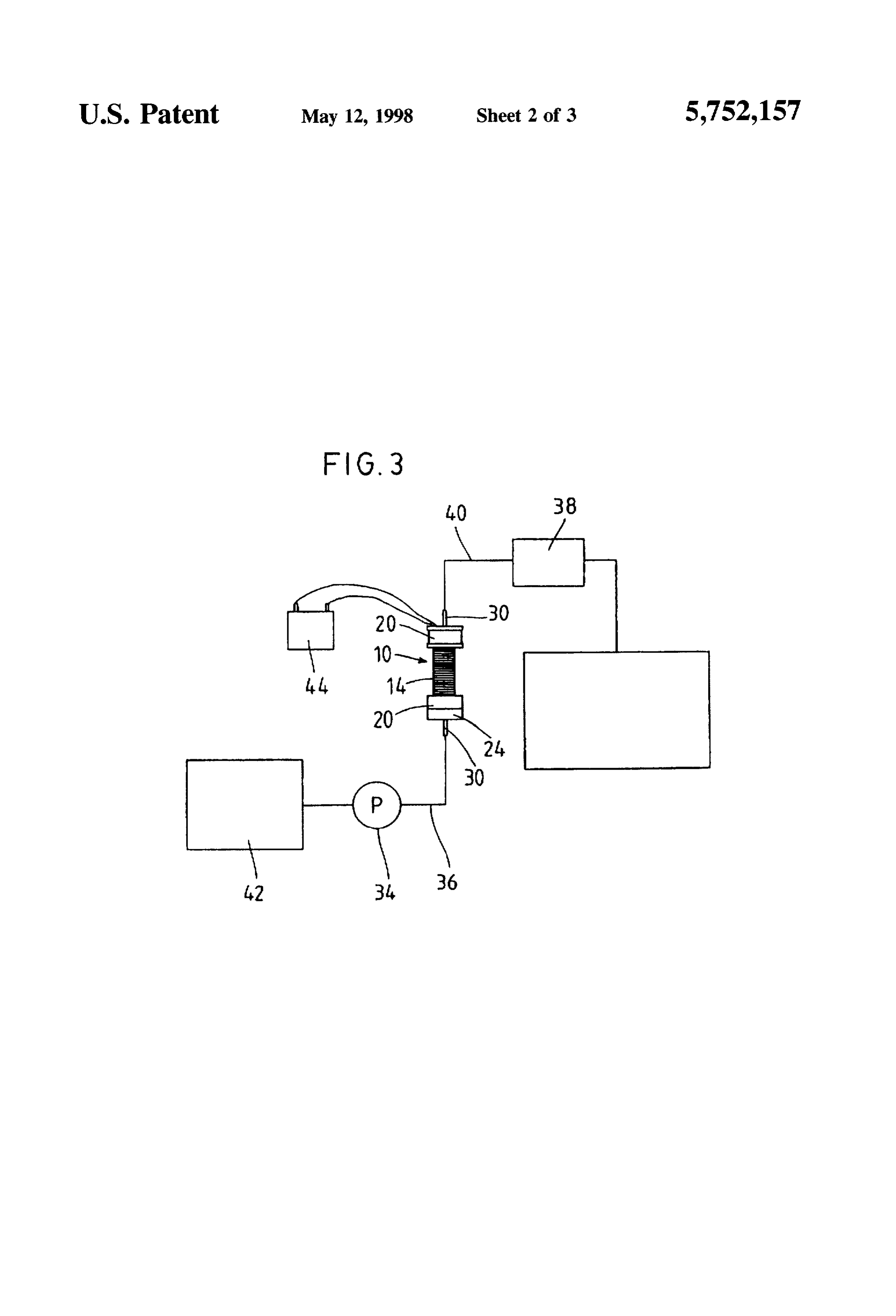
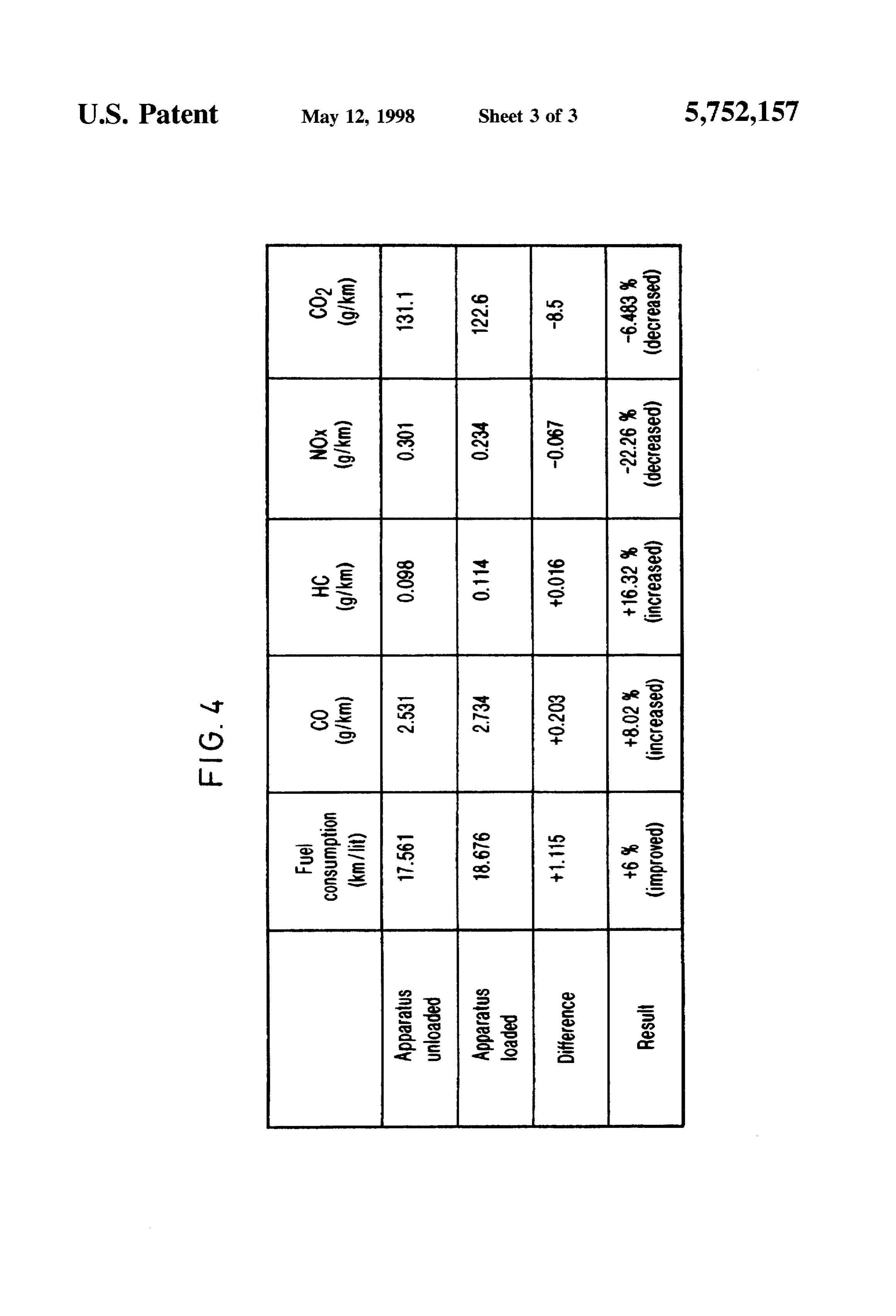
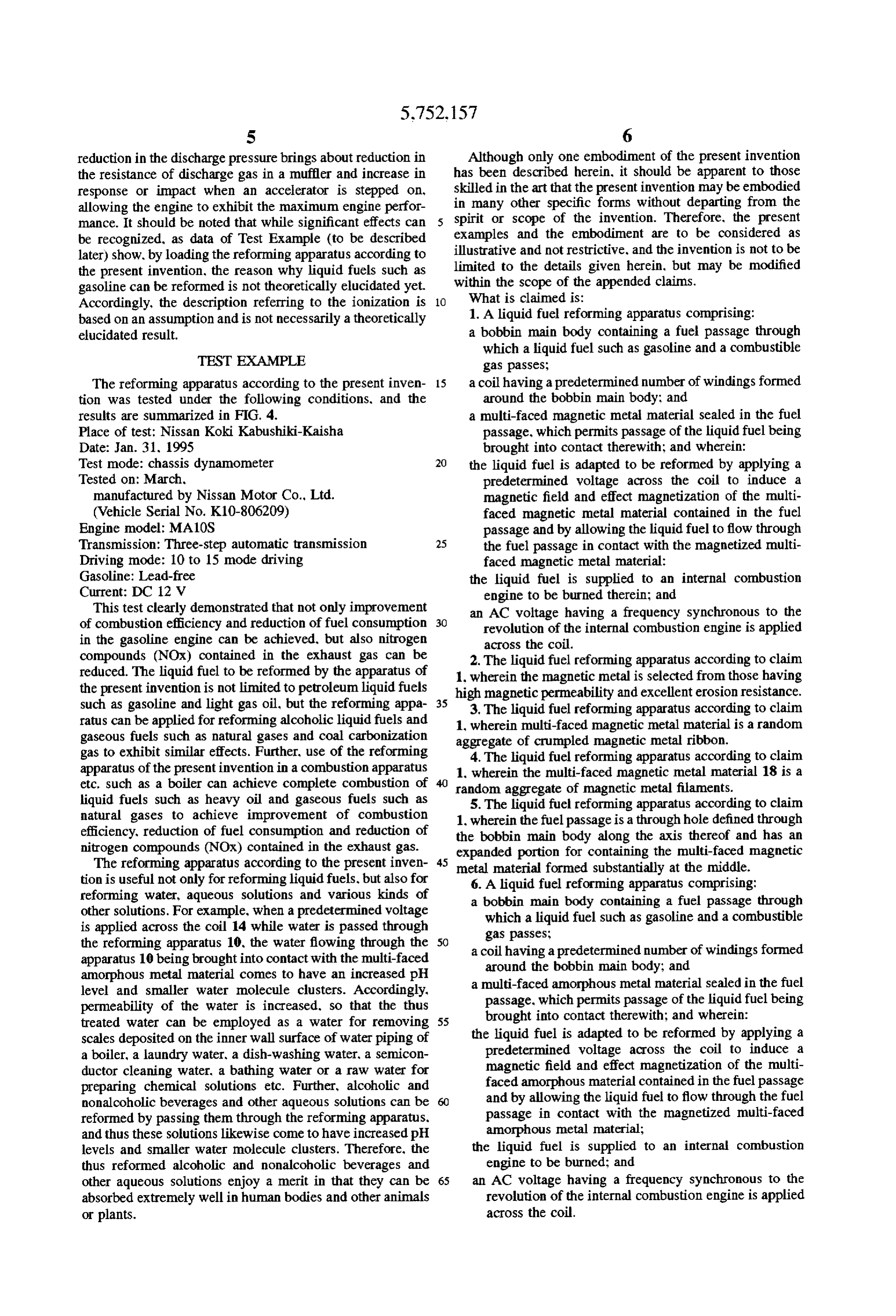
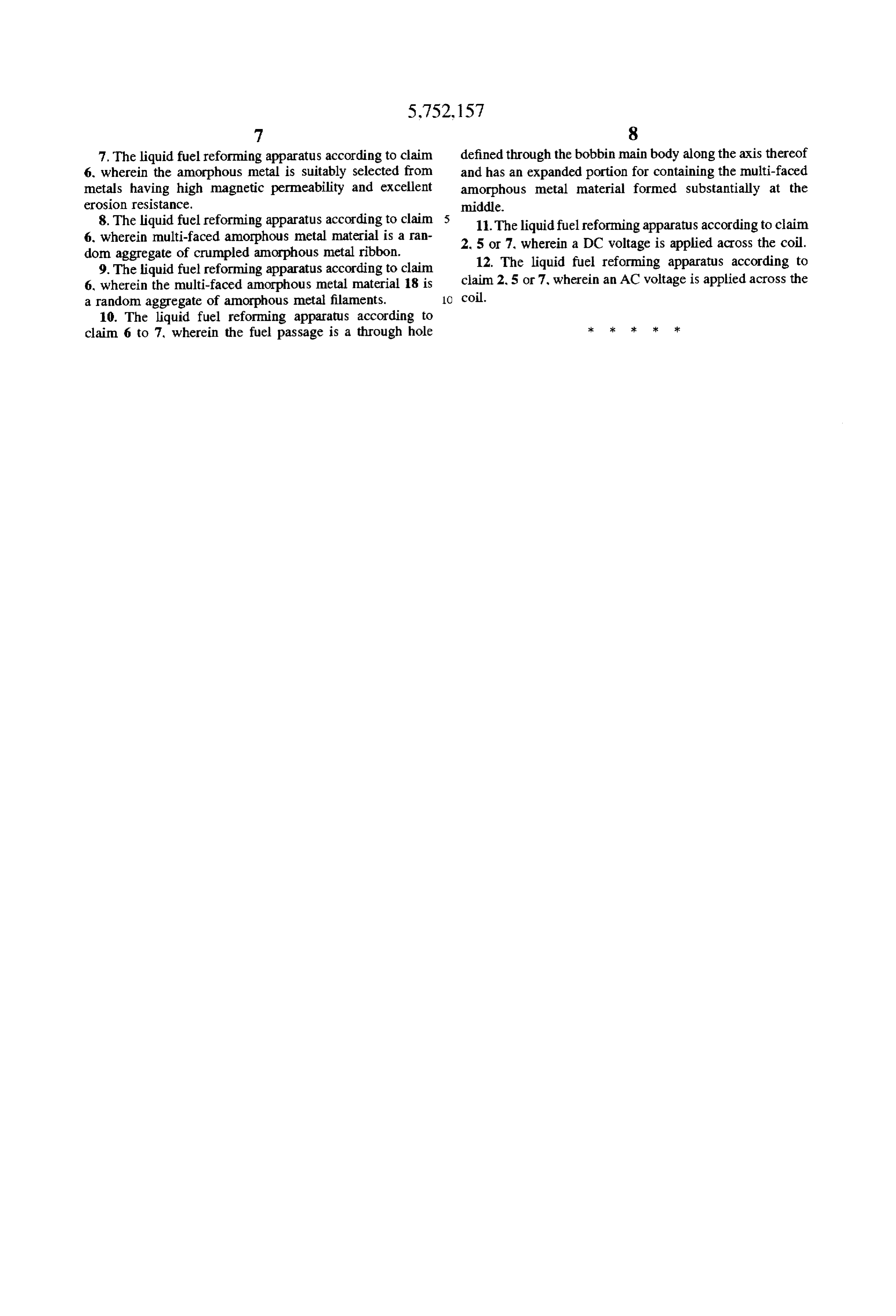
molecular level so as to modify the molecular arrangement FIG. 2 is a partly cut-away perspective view of the liquid and effect activation of the fuel. However, the magnetic field 45 fuel reforming apparatus shown in FIG. 1; induced by the permanent magnet pieces is exerted to the FIG. 3 is an explanatory view showing a state where the gasoline indirectly from the outside of the fuel feeding pipe, liquid fuel reforming apparatus shown in FIG. 1 is connected and further the direction of the magnetic field is fixed. to a fuel supply system of an automotive engine; and Accordingly, the magnetic field does not seem to be pow FIG. 4 is a table showing results of fuel consumption test erful enough to modify the molecular arrangement. Further, 50 carried out using a magnetizing apparatus utilizing an amor referring to the former means which is a special band wound phous metal.
around the ignition plug, the reason why such means can increase combustion efficiency remains absolutely DETALED DESCRIPTION OF THE unelucidated, and no significant data is obtained, as might be 55 PREFERRED EMBODIMENT expected.
SUMMARY OF THE INVENTION
A preferred embodiment of the present invention will be described below referring to the attached drawings. In the
It is an objective of the present invention to provide a preferred embodiment, the reforming apparatus employing a liquid fuel reforming apparatus capable of reforming liquid multi-faced amorphous metal material is attached to a gaso fuels, which has been unattainable by any of the prior artfuel line engine. FIG. 1 shows a longitudinal cross-sectional consumption improving apparatuses, so as to improve com view of a liquid fuel reforming apparatus 10 according to the bustion efficiency in internal combustion engines or com preferred embodiment of the invention. The reforming appa bustion apparatuses and realize improvement of fuel ratus 10 basically consists of a cylindrical bobbin main body consumption, as well as, reduce nitrogen compounds (NOx) 12 made of a nonmagnetic material, a coil 14 wound around contained in exhaust gases. 65 the bobbin main body 12, a fuel passage 16 defined through In order to overcome the problems inherent in the prior art the bobbin main body 12 and a multi-faced amorphous metal and suitably attain the intended objective of the present material 18 sealed in the fuel passage 16 to permit a liquid
Page 6
fuel to flow through the passage 16 being brought into The multi-faced amorphous metal material 18 used in the contact with the multi-faced amorphous metal material 18. above embodiment may be replaced with a multi-faced More specifically, the bobbin main body 12 is made of a magnetic metal material 18. As the magnetic metal, for nonmagnetic material such as a rigid synthetic resin and has example, a ribbon of iron-containing metal having an a pair of flanges 20 having a predetermined diameter at each erosion-resistant plating is employed. More preferably, the longitudinal end thereof A through hole serving as a fuel magnetic metal is selected from those which have high passage 16, which permits passage of a liquid fuel such as magnetic permeability and excellent erosion resistance. In gasoline and a combustible gas, is defined through the this case, as the multi-faced magnetic metal material 18, a bobbin main body 12 along the axis thereof. The liquid random aggregate of crumpled magnetic metal ribbon can be passage 16 has an expanded portion (chamber) 22 substan O suitably employed. Alternatively, the multi-faced magnetic tially at the middle, in which the multi-faced amorphous metal material 18 may be a random aggregate of crumpled metal material 18 (to be describe later) is contained. reticular knitting of magnetic metal filaments. Therefore, in order to facilitate procedures of introducing Next, an actual use of the reforming apparatus according the multi-faced material 18 into the chamber 22, one of the to the embodiment will be described. A predetermined flanges 20 is preferably provided with a separable lid 24 15. amount of multi-faced amorphous metal material 18 is which is detachable with respect to the open end face of that introduced beforehand into the fuel passage 16 of the bobbin flange 20. A seal ring 23 having high oil erosion resistance main body 2 constituting the reforming apparatus. The is applied to the separable lid 24 so as to secure liquid nipples 30 of the bobbin main body 12 are connected to the tightness with respect to the chamber 22. The open end face pipe 36 communicating to the outlet side of the fuel pump of that flange 20 contains a plurality of female screws 25 34 and to the pipe 40 communicating to the inlet side of the arranged in the circumferential direction at predetermined carburetor 38, respectively. Accordingly, gasoline, which is central angular intervals, while the fitting face of the sepa force-fed from a fuel tank 42, by the fuel pump 34 through rable lid 24 also contains a plurality of through holes 26 the pipe 36, passes through the fuel passage 16 defined in the arranged in the circumferential direction at predetermined bobbin main body 12 and then fed through the pipe 40 to the central angular intervals. The separable lid 24 can be 25 carburetor 38. In this process, the gasoline flowing through securely fixed to the flange 20 by screwing bolts 28 into the the fuel passage 16 is brought into intimate contact with the corresponding female screws 25 and through holes 26, multi-faced amorphous metal material 18. Meanwhile, the respectively. The separable lid 24 and the other flange 20 coil 14 wound around the bobbin main body 12 is connected each has a nipple 30, communicating to the fuel passage 16. via the lead wires 32 to an on-vehicle battery 44, which to protrude therefrom outward in the axial direction. These applies a DC voltage of 12V across the coil 14. The 12 V nipples 30 are connected to a pipe 36 communicating to the DC voltage may be converted into an alternate current outlet side of a fuel pump 34 (to be described later) and to employing a converter to apply a predetermined voltage of a pipe 40 communicating to the inlet side of a carburetor 38, alternate current across the coil 14. It should be noted here respectively (see FIG. 3). that, when the gasoline is to be fed to a gasoline engine and Over the zone between the flanges 20 on the cylindrical 35 burned therein, as described above, the revolution of the circumference of the bobbin main body 12, is wound, for engine may be detected by a sensor to convert the direct example, an insulated copper wire having a diameter of 0.5 current supplied from the on-vehicle battery 44 to an alter mm about 2000 times to constitute the coil 14. Lead wires nate current having a frequency synchronous to the revolu 32 are extended from the winding head end and winding tail tion detected by the sensor and then to apply the AC voltage end of the coil 14, and they are to be connected to a 40 across the coil 14. Further, the DC voltage or the AC voltage predetermined DC or AC power source. For example, a DC applied across the coil 14 may be adapted to be interrupted voltage of about 12V is applied across the coil 14, or an AC at regular or random intervals by a suitable switching circuit voltage of about 12V is applied as necessary across the coil interposed between the battery 44 and the coil 14. 14. A magnetic field is induced by applying a predetermined A multi-faced material 18, for example, of an amorphous 45 DC voltage across the coil 14, and the magnetic field acts metal is contained in the expanded portion (chamber) 22 of upon the multi-faced amorphous metal material 18 con the fuel passage 16. In order to introduce the multi-faced tained in the expanded portion (chamber) 22 of the fuel amorphous metal material 18 into the chamber 22, the passage 16 to powerfully magnetize the material 18. If the separable lid 24 is removed from the flange 20 of the bobbin gasoline is force-fed by the fuel pump 34 to the bobbin main main body 12 to open the chamber 22, as described above. 50 body 12 in this state, the gasoline flows in contact with the and after a necessary amount of the multi-faced amorphous powerfully magnetized multi-faced amorphous metal mate metal material 18 is introduced into the chamber 22, the rial 18 and reformed thereby. More specifically, it can be separable lid 24 is applied to the open end face of the flange considered that the gasoline flowing through the fuel pas 20, followed by screwing of the bolts 28 into the corre sage 16 is exposed to magnetic actions exerted from many sponding female screws 25 and through holes 26, 55 directions, when brought into direct contact with the mag respectively, to fix the lid 24, netized multi-faced amorphous metal material 18, and thus The amorphous metal is preferably selected from those the carbon-hydrogen bonds constituting the gasoline which have high magnetic permeability and excellent ero become unstable to release ions (so-called ionization). sion resistance and suitably includes those containing Fe, Ni, This ionization improves (activates) bonding of the gaso Si, Co, B, Cr, etc. For example, Am-Fe73Si10B12 employed line with oxygen when it is burned in the engine, to enable as an iron core material, Am-Fe3Co70Si10B15 suitably substantially complete combustion of the gasoline. If the employed as a high magnetic permeability material, etc. can gasoline is burned substantially completely, not only explo be used. As the multi-faced amorphous metal material 18, a sive force in the cylinders can be increased but also dis random aggregate of crumpled amorphous metal ribbon can charge pressure can be lowered, also reducing nitrogen be suitably employed. Alternatively, the multi-faced amor 65 compounds (NOx) contained in the exhaust gas. The phous metal material 18 may be a random aggregate of increase in the explosive force brings about increase in the crumpled reticular knitting of amorphous metal filaments. engine horse power and in the torque. Meanwhile, the
Page 7
reduction in the discharge pressure brings about reduction in Although only one embodiment of the present invention the resistance of discharge gas in a muffler and increase in has been described herein, it should be apparent to those response or impact when an accelerator is stepped on, skilled in the art that the present invention may be embodied allowing the engine to exhibit the maximum engine perfor in many other specific forms without departing from the mance. It should be noted that while significant effects can spirit or scope of the invention. Therefore, the present be recognized, as data of Test Example (to be described examples and the embodiment are to be considered as later) show, by loading the reforming apparatus according to illustrative and not restrictive, and the invention is not to be the present invention, the reason why liquid fuels such as limited to the details given herein, but may be modified gasoline can be reformed is not theoretically elucidated yet. within the scope of the appended claims. Accordingly, the description referring to the ionization is 10 What is claimed is:
based on an assumption and is not necessarily a theoretically 1. A liquid fuel reforming apparatus comprising: elucidated result. a bobbin main body containing a fuel passage through which a liquid fuel such as gasoline and a combustible
The reforming apparatus according to the present inven 15 a coil having a predetermined number of windings formed tion was tested under the following conditions, and the around the bobbin main body; and results are summarized in FIG. 4. a multi-faced magnetic metal material sealed in the fuel Place of test: Nissan Koki Kabushiki-Kaisha passage, which permits passage of the liquid fuel being Date: Jan. 31, 1995 brought into contact therewith; and wherein: Test mode: chassis dynamometer 20 the liquid fuel is adapted to be reformed by applying a Tested on: March, predetermined voltage across the coil to induce a manufactured by Nissan Motor Co., Ltd. magnetic field and effect magnetization of the multi (Vehicle Serial No. K10-806209) faced magnetic metal material contained in the fuel Engine model: MA10S passage and by allowing the liquid fuel to flow through Transmission: Three-step automatic transmission 25 the fuel passage in contact with the magnetized multi Driving mode: 10 to 15 mode driving faced magnetic metal material: Gasoline: Lead-free the liquid fuel is supplied to an internal combustion Current: DC 12 V engine to be burned therein; and This test clearly demonstrated that not only improvement an AC voltage having a frequency synchronous to the of combustion efficiency and reduction of fuel consumption revolution of the internal combustion engine is applied in the gasoline engine can be achieved, but also nitrogen across the coil.
compounds (NOx) contained in the exhaust gas can be 2. The liquid fuel reforming apparatus according to claim reduced. The liquid fuel to be reformed by the apparatus of 1, wherein the magnetic metal is selected from those having the present invention is not limited to petroleum liquid fuels high magnetic permeability and excellent erosion resistance. such as gasoline and light gas oil, but the reforming appa 35 3. The liquid fuel reforming apparatus according to claim ratus can be applied for reforming alcoholic liquid fuels and 1, wherein multi-faced magnetic metal material is a random gaseous fuels such as natural gases and coal carbonization aggregate of crumpled magnetic metal ribbon. gas to exhibit similar effects. Further, use of the reforming 4. The liquid fuel reforming apparatus according to claim apparatus of the present invention in a combustion apparatus 1, wherein the multi-faced magnetic metal material 18 is a etc. such as a boiler can achieve complete combustion of random aggregate of magnetic metal filaments. liquid fuels such as heavy oil and gaseous fuels such as 5. The liquid fuel reforming apparatus according to claim natural gases to achieve improvement of combustion 1, wherein the fuel passage is a through hole defined through efficiency, reduction of fuel consumption and reduction of the bobbin main body along the axis thereof and has an nitrogen compounds (NOx) contained in the exhaust gas. expanded portion for containing the multi-faced magnetic The reforming apparatus according to the present inven 45 metal material formed substantially at the middle. tion is useful not only for reforming liquid fuels, but also for 6. A liquid fuel reforming apparatus comprising: reforming water, aqueous solutions and various kinds of a bobbin main body containing a fuel passage through other solutions. For example, when a predetermined voltage which a liquid fuel such as gasoline and a combustible is applied across the coil 14 while water is passed through gas passes;
the reforming apparatus 10, the water flowing through the 50 a coil having a predetermined number of windings formed apparatus 10 being brought into contact with the multi-faced around the bobbin main body; and amorphous metal material comes to have an increased pH a multi-faced amorphous metal material sealed in the fuel level and smaller water molecule clusters. Accordingly, passage, which permits passage of the liquid fuel being permeability of the water is increased, so that the thus brought into contact therewith; and wherein: treated water can be employed as a water for removing 55 scales deposited on the inner wall surface of water piping of the liquid fuel is adapted to be reformed by applying a a boiler, a laundry water, a dish-washing water, a semicon predetermined voltage across the coil to induce a ductor cleaning water, a bathing water or a raw water for magnetic field and effect magnetization of the multi preparing chemical solutions etc. Further, alcoholic and faced amorphous material contained in the fuel passage nonalcoholic beverages and other aqueous solutions can be and by allowing the liquid fuel to flow through the fuel reformed by passing them through the reforming apparatus. passage in contact with the magnetized multi-faced and thus these solutions likewise come to have increased pH amorphous metal material;
levels and smaller water molecule clusters. Therefore, the the liquid fuel is supplied to an internal combustion thus reformed alcoholic and nonalcoholic beverages and engine to be burned; and other aqueous solutions enjoy a merit in that they can be 65 an AC voltage having a frequency synchronous to the absorbed extremely well in human bodies and other animals revolution of the internal combustion engine is applied or plants. across the coil.
Page 8
7. The liquid fuel reforming apparatus according to claim defined through the bobbin main body along the axis thereof 6. wherein the amorphous metal is suitably selected from and has an expanded portion for containing the multi-faced metals having high magnetic permeability and excellent amorphous metal material formed substantially at the erosion resistance. middle.
8. The liquid fuel reforming apparatus according to claim 5 11. The liquid fuel reforming apparatus according to claim 6, wherein multi-faced amorphous metal material is a ran 2. 5 or 7, wherein a DC voltage is applied across the coil. dom aggregate of crumpled amorphous metal ribbon. 12. The liquid fuel reforming apparatus according to 9. The liquid fuel reforming apparatus according to claim 6, wherein the multi-faced amorphous metal material 18 is claim 2, 5 or 7, wherein an AC voltage is applied across the a random aggregate of amorphous metal filaments. 1O coil.
10. The liquid fuel reforming apparatus according to claim 6 to 7, wherein the fuel passage is a through hole
Provenance
- Collection
- Cited prior art
- Original PDF
- patentimages.storage.googleapis.com →
- Filed
- 1996-06-14
- Pages
- 8
- Method
- pdftotext (the PDF's own text layer) + pdftoppm 300dpi page scans
- Source
- Google Patents bibliographic record
- Granted
- 1998-05-12
- Inventors
- Takeshi Yamashita; Hiro Yamashita; Centerfield KK
- Transcribed from
- patentimages.storage.googleapis.com →