patent · US20100230362A1
Fluid purification
16 September 2010
Page 1 — bibliographic record
(19) United States (12) Patent Application Publication (10) Pub. No.: US 2010/0230362 A1
Lersch (43) Pub. Date: Sep. 16, 2010 (54) FLUID PURIFICATION (52) U.S. Cl. .......................... 210/695: 210/737; 210/181 (76) Inventor: John R. Lersch, Gallipolis, OH
Correspondence Address: (57) ABSTRACT
ROBERT R. WATERS, ESQ.
WATERS LAW OFFICE, PLLC A fluid purification system and method thereof, the system 633 SEVENTH STREET comprising a plurality of components serially coupled and in HUNTINGTON, WV 25701 (US) fluid communication. A pipe or conduit introduces a fluid into the system and communicates with a charging device that (21) Appl. No.: 12/402,113 removes surface charge(s) from the fluid. The fluid is then transferred to a heater for raising the temperature of the fluid (22) Filed: Mar. 11, 2009 and providing the conditions for precipitating mineral mate Publication Classification rial that generally causes build-up and/or corrosion within such a system. The fluid is then carried to a tank or tanks for (51) Int. C. precipitation of the mineral material. The resulting Supernate CO2F 5/02 (2006.01) and precipitate are transferred to a separator and further sepa CO2F I/48 (2006.01) rated, with the precipitate withdrawn and the filtered fluid CO2F I/58 (2006.01) transferred for additional filtering downstream.
Page 2
Drawing sheet — no readable text.
Page 3
Drawing sheet — no readable text.
Page 4
US 2010/0230362 A1 Sep. 16, 2010
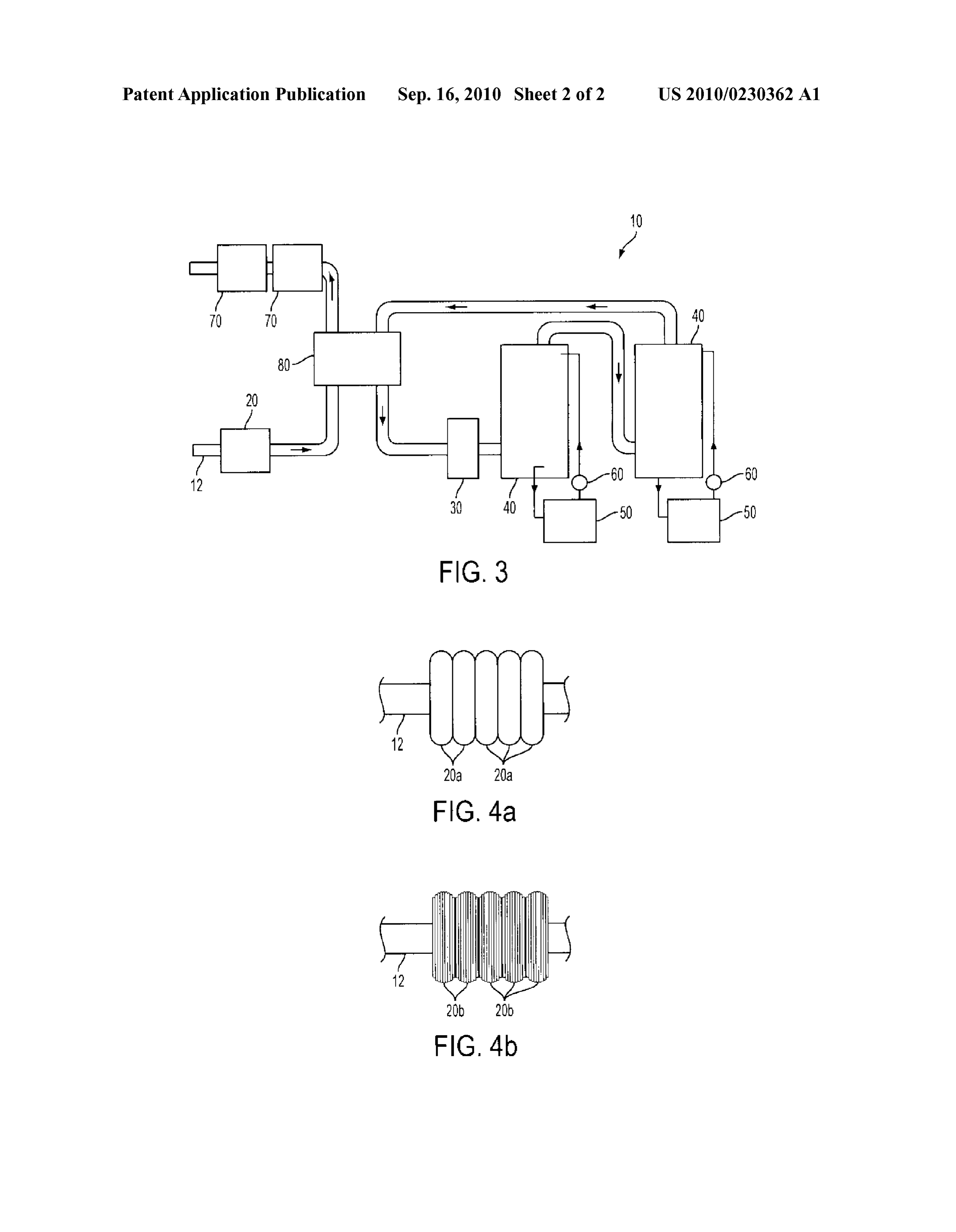
FLUID PURIFICATION 0012 FIG. 4b is a side view of a charging device compris ing a plurality of magnetic coils provided in stacked orienta
0001 Certain embodiments of the invention pertain to DESCRIPTION OF THE EMBODIMENT(S) fluid purification. 0013 As used herein, “fluid may be a solid, liquid, gas or 0002 One non-exhaustive example of related technology other composition that flows and changes its shape or form is described in U.S. Pat. No. 4,956,083, issued to Tovar, when acted upon by a force.
disclosing a water purification device including a hollow 0014. As used herein, a “surface charge” is an electrical casing split into a pair of mating sections releasably con charge generated through the interaction of a material in a nected together for easy access to the inside of the casing. A fluid.
water pipe is disposed in the casing, extends out opposite ends 0015. As used herein, "coupled may include compo thereof and bears connectors for connection to water-bearing nents, apparatuses, devices or other articles that are joined or plumbing and the like. A non-rotating removable and replace otherwise attached, such as movably or fixedly, by one or able water impeller having a spaced number of blade seg more intermediate components, apparatuses, devices or other ments is disposed longitudinally on the water pipe to control articles.
mixing and the residence time of water passing through the 0016. As used herein, “in electrical communication' may pipe. The impeller can be in the form of a single helix or in the include components, apparatuses, devices or other articles form of a flexible accordion-pleated band which is longitudi that transfer electrical energy through one or more interven nally urgeable between a collapsed and an extended position ing components, apparatuses, devices or other articles and/or to control the number and pitch of the blade segments or in which the transferred electrical energy is modified as part pleats in a selected portion of the pipe. That selected portion of the transfer.
is disposed in an electromagnetic coil in the casing, which 0017. As used herein, “in fluid communication' includes coil, when energized, causes sediment in the water to dissolve the flow of fluid from one components, apparatus, device, and pulverize. The coil is energized through electrical com article or region to another component, apparatus, device, ponents in the casing, including a condenser, a transformer, a article or region; such flow may be achieved by way of one or resistor and electrical circuitry interconnected to the coil. The more intermediate (and not specifically mentioned or device is compact and efficient. This example, as well as other described) other components, apparatuses, devices, articles related technology, discloses multi-stage Vessels using indi or regions, and such flow may or may not be selectively vidual separator/coalescer filter elements to separate Solids, interruptible (such as by a valve, switch, control or other filter liquids, and coalesce liquids. Suitable component).
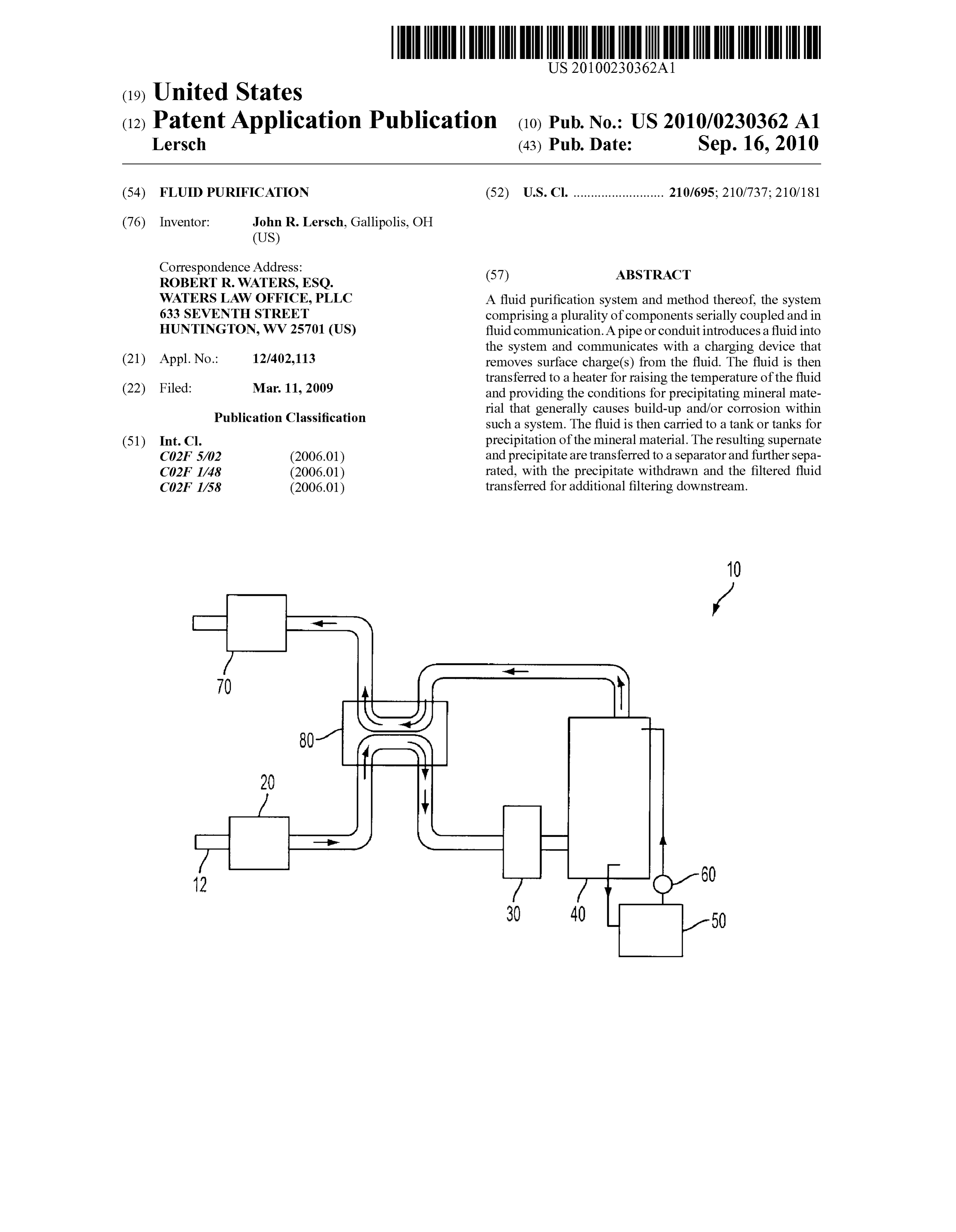
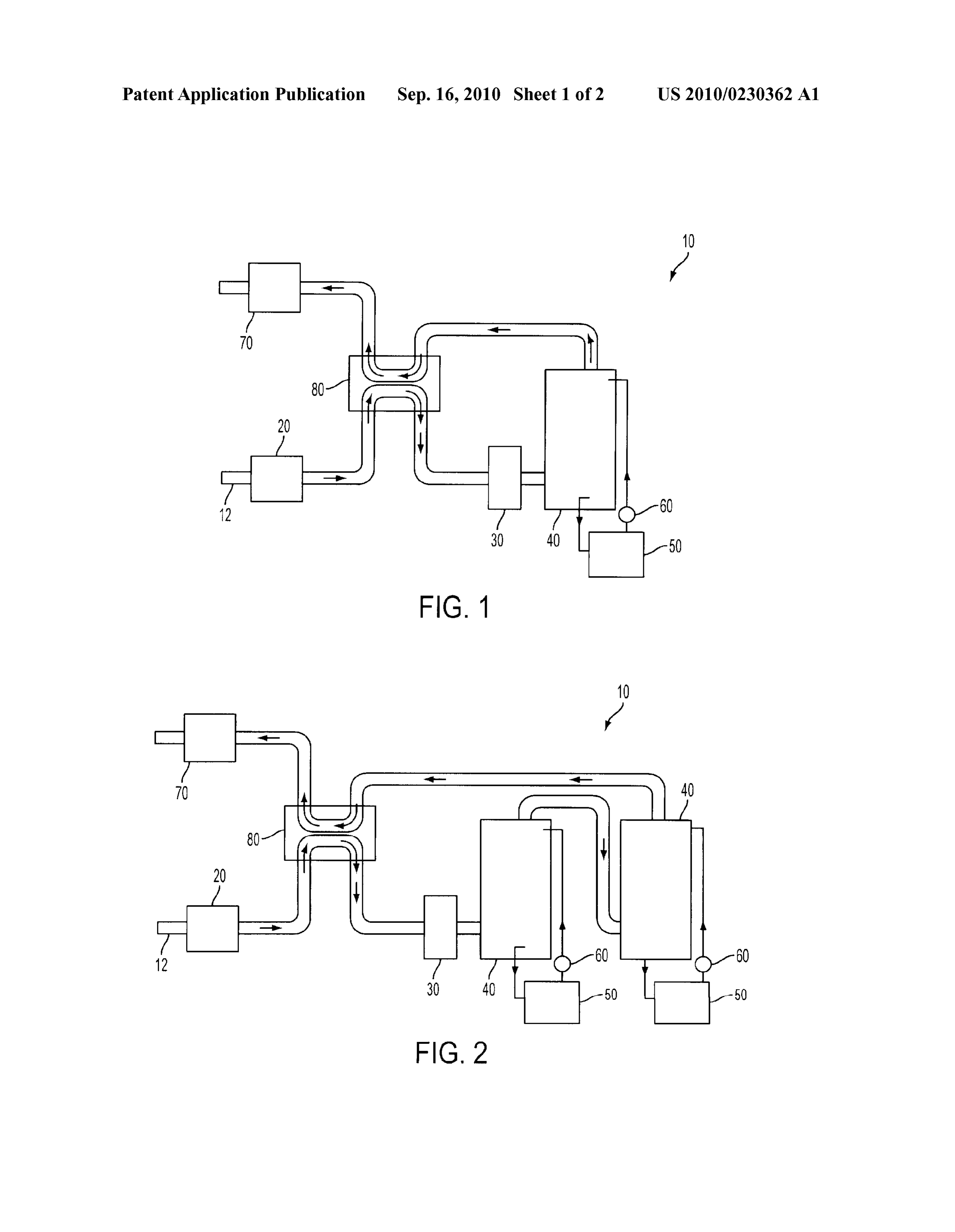
0003 Certain embodiments of the invention represent 0018 Referring now to FIG. 1, a purification system for improvements pertaining to purifying a quantity of fluid. removing contaminants and other unwanted or undesirable particulates from a fluid is depicted and generally denoted by
SUMMARY the reference character 10. In one embodiment, the system 10 may comprise a charging device 20, a heater 30, at least one 0004 Certain embodiments of the invention include a fea precipitation tank 40, a separator 50, a pump 60, and at least ture for improving the quantity of particulates removed from one filter 70. In this embodiment, the system 10 and its vari a fluid directed through the fluid purification device. ous components may be directly or indirectly coupled by one 0005 Certain embodiments of the invention include a or more pipes or conduits 12 provided within, through and/or charging device removing Surface charge(s) from the fluid. In between the components. In another embodiment, the system one embodiment, the charging device may comprise one or 10 may further comprise aheat exchanger 80. In this embodi more magnets. In another embodiment, the charging device ment, the system 10 and its various components may be may comprise one or more electromagnetic coils. directly or indirectly coupled by one or more pipes or con 0006 Certain embodiments of the invention include aheat duits provided within, through and/or between the compo exchanger generating additional and regenerative heat nents. In the embodiments, the various components may be applied to the inbound fluid. collectively or separately supplied with electricity for opera tion.
0007. The “Summary of the Invention” is provided merely to introduce certain concepts. The "Summary of the Inven 0019. It is envisioned that the most common fluid interact tion' is not intended to identify any key or essential feature of ing with the system 10 is water, though other fluid materials and combinations of water with these other fluid materials are the claimed Subject matter. contemplated.
BRIEF DESCRIPTION OF THE DRAWINGS 0020. A pipe or conduit 12 supplies and introduces an inbound current of fluid “F” to the system 10. In one embodi 0008 FIG. 1 is a schematic of one embodiment of a min ment, a water circulation system provides the quantity of eral precipitation system; water (as the fluid) introduced into the system for purification via the pipe 12. The pipe 12 may pass through or by the 0009 FIG. 2 is a schematic of another embodiment of a charging device 20. In one embodiment, the charging device mineral precipitation system; 20 may comprise one or more annular magnets 20a disposed 0010 FIG. 3 is a schematic of another embodiment of a in a stacked orientation. In another embodiment, the charging mineral precipitation system; device 20 may comprise one or more electromagnetic coils 0011 FIG. 4a is a side view of a charging device compris 20b disposed in a stacked orientation. It is envisioned that the ing a plurality of magnets provided in a stacked orientation; polarity of each magnet 20a or coil 20b in the stacked orien and tation may be similar or variable when comparing adjacent
Page 5
US 2010/0230362 A1 Sep. 16, 2010
magnets 20a or coils 20b. It is further envisioned that one fluid and the minerals bonded therewith. As the precipitate embodiment includes a configuration in which the magnets forms, adding mass and generally under the influence of 20a or coils 20b have sequentially or serially opposing polari gravity, the precipitate particles descend to the base or floor of ties. As but one example, it is envisioned that one configura the tank 40. The tank 40 is coupled to a separator 50 for tion of the magnets 20a or coils 20b may include alternating further treatment of the precipitate. polarities, such as N-S, S-N,N-S, S-N. Other configurations 0026. The separator 50 may comprise a variety of com are contemplated, as well. The electromagnetic coils 20b may mercially available separators, including a centrifugal sepa be energized by one of the following arrangements, including rator, a vacuum separator or other similar and Suitable sepa electrical current from a source. rator that may be incorporated into the aforementioned 0021 Magnets 20a or coils 20b remove surface (electri system 10. The separator 50 further separates precipitate cal) charges from the minerals carried by the fluid “F”, the material from the fluid transferred to the separator 50. As the Surface charge(s) generated by the interaction of the mineral precipitate forms, and accumulates, the yield descends to the (s) in the fluid. In removing the Surface charge(s) of the base or bottom of the separator 50, with the residual fluid mineral(s), cleavage of any bonding or attraction between the circulated into the tank 40 by a variety of ways, including the fluid (e.g. water) and the mineral(s) is optimized, thereby use of a pump 60 within the system 10. The precipitate may allowing the mineral(s) to more freely precipitate from the then be permanently removed from the system 10 via a sepa fluid under the appropriate conditions. The resulting precipi rate discharge or through periodic cleaning or maintenance. tate may then be separated from the remaining Supernate 0027. The pump 60 may be disposed between and opera (liquid) portion. The precipitate represents a significant quan tively coupled between the separator 50 and the tank 40, with tity of the undesirable mineral build-up experienced in water the pump 60 inducing flow of the separated fluid from the or fluid circulation and/or filtering systems. Thus, optimizing separator 50 back into the tank 40. Thereafter, the fluid may separation of the precipitate from the fluid (e.g. water), and be induced into circulation for further treatment by another discarding the precipitate, represents an improvement over tank 40/separator 50/pump 60 configuration, a heat other systems in improving fluid purification and reducing exchanger 80 or one or more filters 70. It is envisioned that a maintenance and/or replacement of elements or components combination or Subcombination of one or more of these com of the system 10. ponents may be utilized in the purification of the fluid after a 0022. In embodiments in which the fluid is water, the first purification through the tank 40/separator 50/pump 60 water passes through the pipe 12 and either through or by the configuration is performed.
magnets 20a or coils 20b removing the static charge and 0028. It is envisioned that at least one filter 70, and con starting the crystal nucleation process that continues through ceivably multiple filters 70, may be utilized in the system 10, the system and into the tank(s) 40 utilized in precipitating the the filter or filters 70 coupled with the pipe or conduit 12 mineral material from the water. delivering or transporting the resulting outbound fluid 0023 The heating unit or heater 30, or a plurality of heat throughout the system 10. In one embodiment, one or more ers comprising a heating unit 30, may be utilized to increase filters 70 are positioned near the end of the purification system the temperature of the fluid (e.g. water) beyond a threshold 10 (and process), the filter(s) 70 further capturing any residual conducive for precipitation of the solid mineral material from precipitate or other solid or semi-solid material that may be the fluid material. In one embodiment, the heater(s)30 may be trapped or entrained by the filter media(-um) utilized in the in fluid communication with the charging device 20. In filter(s)70. It is also envisioned that one or more filters 70 may another embodiment, described below that may utilize a heat be disposed at various places and stages within the system 10 exchanger 80, the heater(s) 30 may be in fluid communication (and process). If the fluid, including water, is heavily con with the heat exchanger 80. A pipe or component of the pipe taminated with minerals or other undesirable properties, the 12 may provide the fluid coupling or communication between use of one or more filters 70 within the system 10 (and the heater(s)30 and the charging device 20, or the heater(s)30 process) may yield better purification for the fluid without and the heat exchanger 30, respectively. Downstream, the having to re-circulate the fluid through the entire system 10 fluid may be transferred to one or more tanks 40 via the pipe (and process).
12, a component of the pipe 12, or other conduit for transfer 0029. If optionally included, the heat exchanger 80 may be ring fluid to the tank(s) 40. disposed to take advantage of the heat carried by the fluid 0024. It is envisioned that the temperature range necessary from the circulation of partially treated or purified fluid to to force precipitation is between 120° F. and 180° F. The heat the inbound current of fluidjust entering the purification variability within the range will accommodate variable system. As depicted in FIG. 1, the heat exchanger 80 may be chemical characteristics and process parameters for a particu disposed between the charge device 20 and heating unit or lar fluid sample and purification or precipitation systems. heater(s) 30 on the inbound stage, and disposed between the Heating the fluid lowers the saturation point of the fluid and tank(s) 40 and the filter(s) 70 on the outbound stage. In this increases the crystallization process that yields a separable configuration, the heat exchanger 80 is envisioned as com precipitate. The velocity of the fluid is such that the precipi prising a countercurrent or cross-current exchanger. For tate is not generated until transfer of the fluid into one or more example, the specific depiction of FIG. 1 is that of a counter tank(s) 40 within the system. current exchanger, in which the inbound current and out 0025. The tank 40, or a plurality of tanks 40, may be used bound current passing through the exchanger are oriented in for facilitating precipitation of the solid material once the opposite directions (though flowing parallel or Substantially temperature threshold parameter is satisfied. Once the heated parallel through the system 10). In a cross-current (cross fluid (e.g. water) enters the tank 40, the velocity of the fluid is flow) exchanger, the inbound current and outbound current slowed so that the precipitate is formed. The precipitate may are oriented at Some angle to one another that is not substan have many textural or structural forms, including flakes, pow tially parallel in orientation. These types of exchangers opti der or grain, generally influenced by the composition of the mize the heat created by the system 10 by transferring the heat
Page 6
US 2010/0230362 A1 Sep. 16, 2010
by-product from the purification to the inbound fluid current 5. The method of claim 1 further comprising the step of that is to be heated in various stages. In this arrangement, the heating the fluid includes introducing the fluid into a heat heat required from the heater(s) 30 is reduced, thereby reduc exchanger.
ing the strain on the heater(s)30 and extending the usable life 6. The method of claim 1 further comprising the step of thereof. However, the heat exchanger 80 is not limited to these repeating the separating of the minerals from the fluid by particular configurations or apparatuses, and may comprise introducing the fluid into a second tank. various types of exchangers commercially available. 7. A fluid purification system comprising: 0030. It is to be understood that the embodiments and a charging device;
claims are not limited in application to the details of construc a heater;
tion and arrangement of the components set forth in the at least one precipitation tank; description and illustrated in the drawings. Rather, the a separator in fluid communication; description and the drawings provide examples of the a pump;
embodiments envisioned, but the claims are not limited to any at least one filter; and particular embodiment or a preferred embodiment disclosed at least one conduit in fluid communication with the charg and/or identified in the specification. The drawing figures are ing device through the at least one filter. for illustrative purposes only, and merely provide practical 8. The system of claim 7, wherein the charging device examples of the invention disclosed herein. Therefore, the comprises at least one magnet.
drawing figures should not be viewed as restricting the scope 9. The system of claim 8 further comprising a plurality of of the claims to what is depicted. magnets disposed in a stacked configuration. 0031. The embodiments and claims disclosed herein are 10. The system of claim 9, wherein the plurality of magnets further capable of other embodiments and of being practiced are arranged in alternating polarities. and carried out in various ways, including various combina tions and sub-combinations of the features described above 11. The system of claim 7, wherein the charging device but that may not have been explicitly disclosed in specific comprises at least one electromagnetic coil. combinations and Sub-combinations. Accordingly, those 12. The system of claim 11 further comprising a plurality of skilled in the art will appreciate that the conception upon electromagnetic coils disposed in a stacked configuration. which the embodiments and claims are based may be readily 13. The system of claim 12, wherein the plurality of elec utilized as a basis for the design of other structures, methods, tromagnetic coils are arranged in alternating polarities. and systems. In addition, it is to be understood that the phrase 14. The system of claim 7, wherein the heater raises the ology and terminology employed herein are for the purposes temperature of the fluid to between approximately 120°F. and of description and should not be regarded as limiting the 180° F.
claims. 15. A fluid purification system comprising: 0032. Furthermore, the Abstract is neither intended to a charging device;
define the claims of the application, nor is it intended to be a heat exchanger, limiting to the Scope of the claims in any way. It is intended a heater;
that the application is defined by the claimed appended at least one precipitation tank; hereto. a separator in fluid communication with the tank; What is claimed is: a pump in fluid communication with the separator and the 1. A method for removing mineral impurities from a fluid, tank;
the method comprising the steps of at least one filter; and removing Surface charges from a fluid introduced there at least one conduit in fluid communication with the charg with: ing device through the at least one filter. heating the fluid; 16. The system of claim 15, wherein the charging device separating the minerals from the fluid yielding a precipitate comprises at least one magnet.
and a Supernate; 17. The system of claim 16 further comprising a plurality of introducing the Supernate and the precipitate into a sepa magnets disposed in a stacked configuration. rator, separating the Supernate and the precipitate; 18. The system of claim 17, wherein the plurality of mag withdrawing the precipitate; nets are arranged in alternating polarities. pumping the fluid to a first tank; 19. The system of claim 15, wherein the charging device introducing the fluid to at least one filter; and comprises at least one electromagnetic coil. separating residual minerals from the fluid via the at least 20. The system of claim 19 further comprising a plurality of one filter. electromagnetic coils disposed in a stacked configuration. 2. The method of claim 1, wherein the step of removing 21. The system of claim 20, wherein the plurality of elec Surface charges from a fluid includes the fluid communicating tromagnetic coils are arranged in alternating polarities. with a charging device. 22. The system of claim 15, wherein the heater raises the 3. The method of claim 1, wherein the step of heating the temperature of the fluid to between approximately 120°F. and fluid includes raising the temperature of the fluid to between 180° F.
120° F. and 180° F. 23. The system of claim 15, wherein the heat exchanger is 4. The method of claim 1, wherein the step of separating the disposed between the charging device and the tank. minerals from the fluid includes introducing the fluid into the c c c c c first tank.

Provenance
- Collection
- Patents citing this work
- Pages
- 6
- Method
- pdftotext (the PDF's own text layer) + pdftoppm 300dpi page scans
- Patent office record
- patents.google.com →
- Source
- Google Patents citing-documents table
- Assignee
- Lersch John R
- Inventors
- John R. Lersch
- Published
- 2010-09-16
- Transcribed from
- patentimages.storage.googleapis.com →