patent · US1905627
Apparatus for electrolysis
25 April 1933
Page 1
Drawing sheet — no readable text.
Page 2
Patented Apr. 25, 1933 1905,627
UNITED STATES PATENT OFFICE
WALTER HOLLAND, OF WASHINGTON, DISTRICT OF COLUMBIA
APPARATUS FOR ELECTROYSIS
Application filed September 24, 1930. Serial No. 484,147.
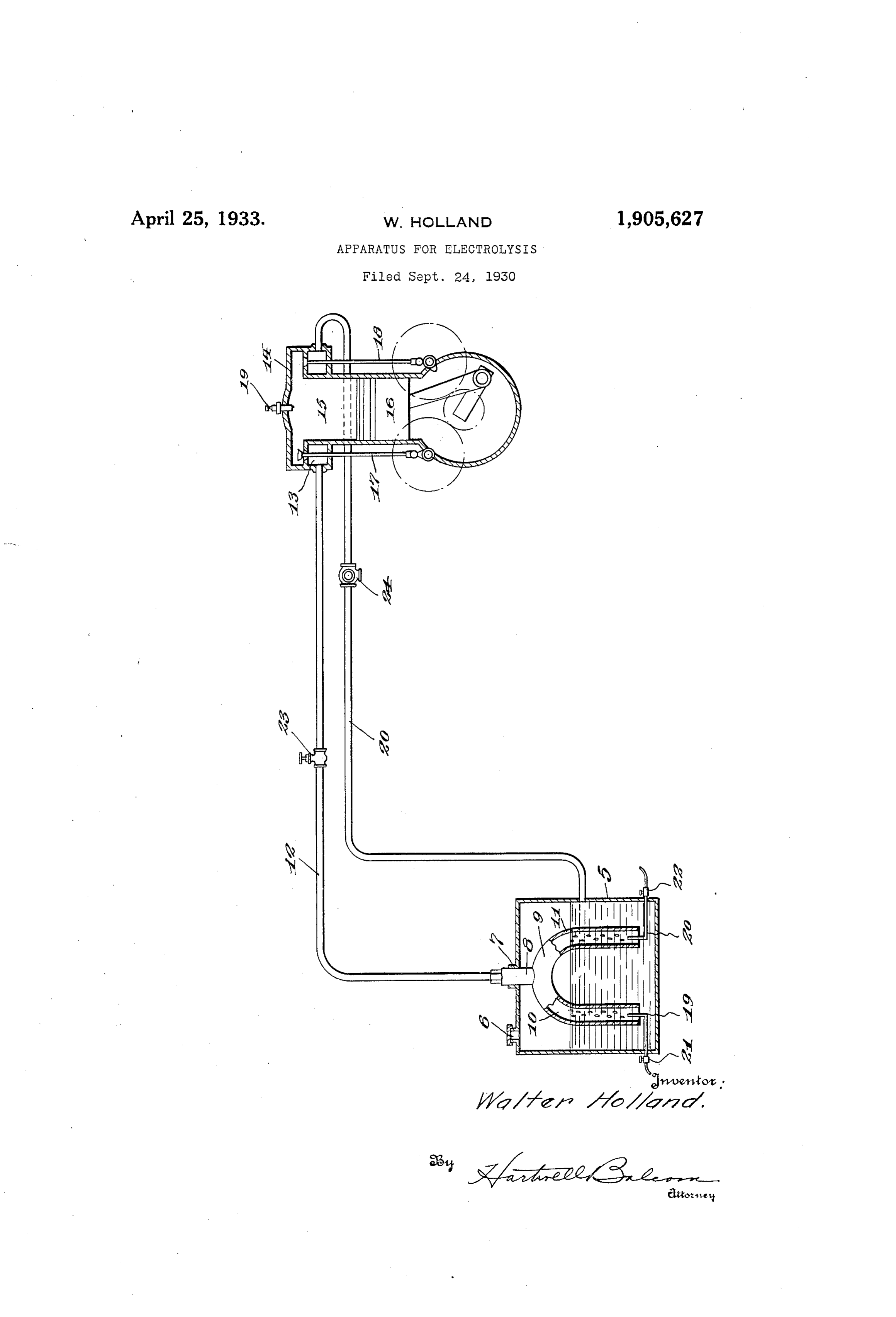
This invention relates to a method for ing the fabrication of said receptacle, said converting molecular energy into mechanical vessel may be built therein if desired. energy, and an apparatus therefore. Leading from said extension 8, of said Primarily, the object of the present inven vessel 9, is a conduit 12, its other end being 5 tion resides in the provision of an apparatus suitably connected to the intake chamber 13 55 of the above-mentioned character wherein of an engine, generally denoted by the nu the decomposition of a liquid, such as water, meral 14, and it will be observed that said is effected by electricity, for the liberation engine includes the usual chamber 15, piston of its gases. 16, intake valve mechanism 17 and exhaust 0 Another object is to provide means where valve mechanism 18. While the drawing 60 by said gases, under control, may be intro shows a well-known type of internal combus duced as a detonating mixture into a con tion engine, it will be understood that the fined space, such as the explosive chamber of same is illustrative, rather than restrictive, in an engine, and subjected to the influence of that my improvement is operable in connec 5 an electric spark for the great disengagement tion with any type of engine adapted to be op 65 of heat and acquired expansive force. Eted by the expansive force of a gas or the Still another object of the invention is to like.
provide means whereby said liquid may be Reverting now to said receptacle 5, it will decomposed, as aforesaid, and the liberated be observed that electrodes 19 and 20 are fitted O 20 gases collected for passage to said confined within said members 10 and 11, which extend
Space. to binding posts 21 and 22 respectively, to A still further object resides in the provi which latters may be connected suitable wires sion of means whereby the products of the leading from a convenient source of electric detonating mixture may be returned to its ity, (not shown). In view of this arrange 5 25 Source of supply or exhausted into the at mosphere. ment the interposition of the above in an electric circuit causes a decomposition of the
With these objects in view, together with water and the liberation of hydrogen at the others which will appear as the description negative electrode 20 and the liberation of proceeds, the invention resides in the novel oxygen at the positive electrode 19. As the 80 30 formation, combination, and arrangement of bubbles of these gases rise in said vessel 9 parts, all as will be described more fully they are collected within the extension 8 and hereinafter, illustrated in the drawing and passed, under control, to said inlet chamber particularly pointed out in the claims. 13 by way of conduit 12, valve 23 being inter 35 The drawing illustrates an elevation of posed in the latter to regulate the passage of 85 the apparatus, partly in section, and dia said gases.
grammatically showing the arrangement of As heretofore pointed out, the gases are parts. introduced as a detonating mixture of hydro Referring now more in detail to the ac gen and oxygen into said inlet chamber for subsequent passage into the chamber 15 of 40 companying drawing, let 5 indicate a recep said engine 14, and as is well-known said mix 90 tacle of suitable proportions and adapted to ture contain a supply of liquid, such as water, comprises two volumes of hydrogen and said receptacle having a filling opening 6 for oneWhen of oxygen.
the replenishment of its contents as needed. tric sparksaida mixture is subjected to an elec great disengagement of heat en 95 45 It will be noted that said receptacle is suit ably apertured, as indicated at 7, through 68,924 thermal units, of sues, said liberation and heat amounting to since each unit is which projects the extension 8 of the vessel equivalent to over 1300 foot-pounds, the ac 9, the latter including members 10 and 11 quired expansive force may be utilized to op having their lower ends open and spaced erate a moving body such as a piston. 50 from the bottom of said receptacle 5. Dur In the drawing the piston is shown as op 100
Page 3
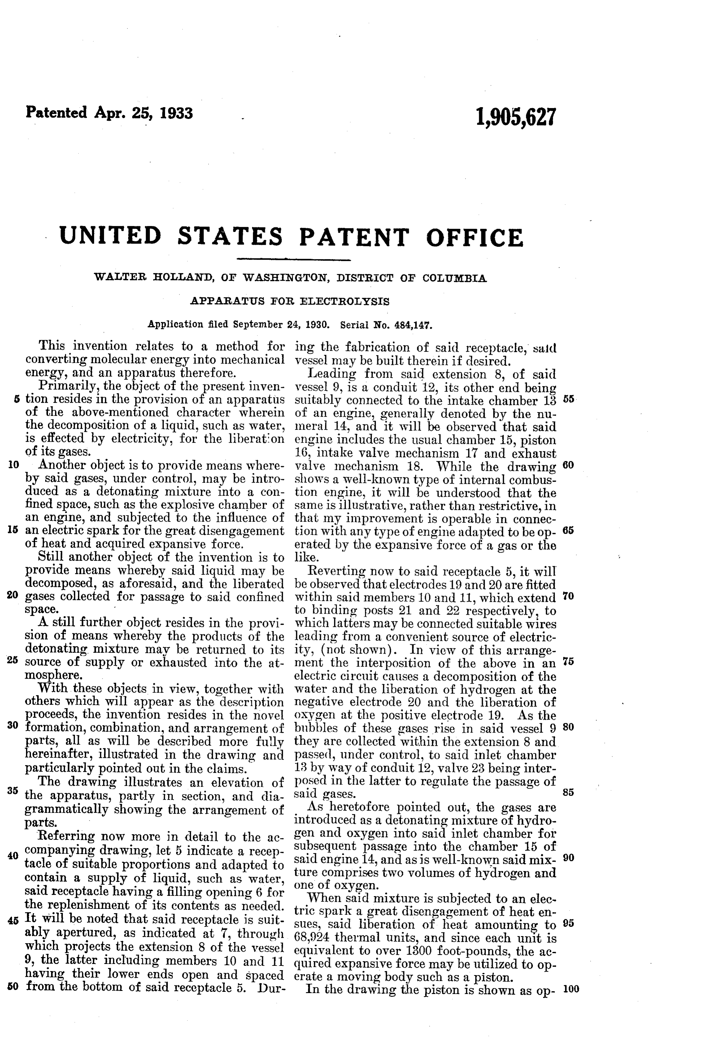
erating to draw in the above-mentioned de tonating mixture, and it will be observed that the inlet valve mechanism 17 is operated to permit the passage of said mixture into the chamber 15. As the piston rises to compress this mixture, both valve mechanisms 17 and 18 are operated to close the inlet and exhaust orts and shortly after the piston reaches its ighest point, the charge of the mixture is O E. to a spark from the plug 19, which is connected to a suitable source of electrical energy, (not shown), and the working stroke then takes place, both valves remaining closed. After said working stroke, the pis ton rises and the exhaust valve opens to per mit the products to escape through the con duit 20 back to the receptacle 5, said products being now in the form of a steam. If desired a three-way valve 24 may be interposed in 20 said conduit 20, which is susceptible of oper ation to discharge the products into the at mosphere.
Having thus fully described this invention, I hereby reserve the benefit of all changes in form, arrangement, order, or use of parts, as it is evident that many minor changes may be made therein without departing from the spirit of the invention or the scope of the fol lowing claims.
30 I claim:
1. A device of the class described compris ing, a receptacle, a supply of liquid within said receptacle, a vessel positioned within said receptacle, said vessel including a pair of 85 members having their open ends extended into the liquid and spaced from the bottom of said receptacle, said members uniting to present a gas-collecting chamber with the re ceptacle and electrodes of opposite polarity, 40 one electrode being positioned within each of said members of said vessel.
2. An electrolyzer adapted to be positioned in a receptacle containing a liquid, and com prising a U-shaped body portion presenting 45 a pair of members having their open ends extended into the liquid, there being a gas collecting chamber positioned above the top of said members, an extension leading from said chamber and electrodes of opposite 50 polarity, one electrode being positioned with in each of said members.
In testimony whereof I affix my signature.
WALTER HOLLAND.
Provenance
- Collection
- Cited prior art
- Original PDF
- patentimages.storage.googleapis.com →
- Filed
- 1930-09-24
- Pages
- 3
- Method
- pdftotext (the PDF's own text layer) + pdftoppm 300dpi page scans
- Source
- Google Patents bibliographic record
- Granted
- 1933-04-25
- Inventors
- Holland Walter
- Transcribed from
- patentimages.storage.googleapis.com →