patent · US20110259671A1
Divider Device for Flow of Lubricant and Lubrication System
27 October 2011
Page 1 — bibliographic record
(19) United States (12) Patent Application Publication (10) Pub. No.: US 2011/0259671 A1
Amilien et al. (43) Pub. Date: Oct. 27, 2011 (54) DIVIDER DEVICE FOR FLOW OF Publication Classification
LUBRICANT AND LUBRICATION SYSTEM
(76) Inventors: Guillaume Amilien, Vivy (FR); 52 Eelyn (2006.01) 184/6.26 Régis Page, Bagneux (FR) (52) U.S. Cl. .......................................................
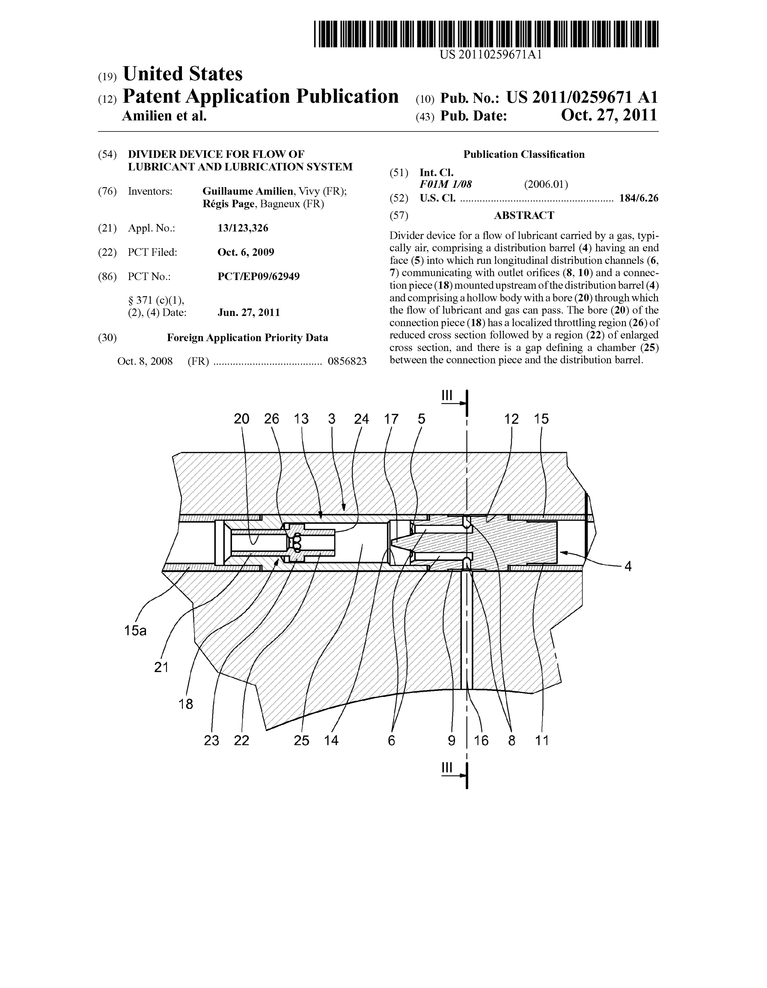
(21) Appl. No Divider device for a flow of lubricant carried by a gas, typi (22) PCT Filed: Oct. 6, 2009 cally air, comprising a distribution barrel (4) having an end 9 face (5) into which run longitudinal distribution channels (6.
(86). PCT No.: PCT/EP09/62949 7) communicating with outlet orifices (8, 10) and a connec tion piece (18) mounted upstream of the distribution barrel (4)
S371 (c)(1), and comprising a hollow body with a bore (20) through which (2), (4) Date: Jun. 27, 2011 the flow of lubricant and gas can pass. The bore (20) of the connection piece (18) has a localized throttling region (26) of (30) Foreign Application Priority Data reduced cross section followed by a region (22) of enlarged cross section, and there is a gap defining a chamber (25)
Oct. 8, 2008 (FR) ....................................... O856823 between the connection piece and the distribution barrel.
Frr AZA
15a -
Page 2
Drawing sheet — no readable text.
Page 3
Drawing sheet — no readable text.
Page 4
Drawing sheet — no readable text.
Page 5
Drawing sheet — no readable text.
Page 6
US 2011/0259671 A1 Oct. 27, 2011
DIVIDER DEVICE FOR FLOW OF 0010. The present invention also relates to a divider device LUBRICANT AND LUBRICATION SYSTEM in which the atomization of the lubricant into minute droplets occurs regardless of the loss of head or the backpressure downstream of the device. The result is an equalized distri 0001. This invention relates to lubrication by atomization bution of the lubricant at various lubrication points of a given of lubricant carried by a gas, typically compressed air. system.
0002 The bearings of machine-tool shafts and spindles 0011. The invention also relates to a divider device that and rolling-contact bearings used in rolling mills and levellers eliminates the faults of operation resulting from the lubricant for steelworks are generally lubricated by a centralized sup build-up in the divider device.
ply of lubricant delivering a flow of lubricant carried by a gas, 0012. In one embodiment, a divider device for a flow of typically compressed air. The mixture of air and lubricant is lubricant carried by a gas, typically air, comprises a distribu carried by pipes to the lubrication points where the lubricant tion barrel having an end face into which run longitudinal must be delivered in the form of a mist of fine droplets of distribution channels communicating with outlet orifices and lubricant carried by the gas stream. The lubricant is carried a connection piece mounted upstream of the distribution bar along the pipes to the lubrication points in the form usually of rel and comprising a hollow body with a bore through which a film of lubricant propelled by the air current. This mixture the flow of lubricant and gas can pass. must therefore be modified to turn it into a mist consisting of 0013 The bore of the connection piece has a localized a multitude of minute droplets of lubricant for each lubrica throttling region of reduced cross section followed by a tion point. region of enlarged cross section. There is a gap defining a 0003. The various lubrication points are therefore pro chamber between the connection piece and the distribution vided with divider devices designed to atomize the lubricant barrel.
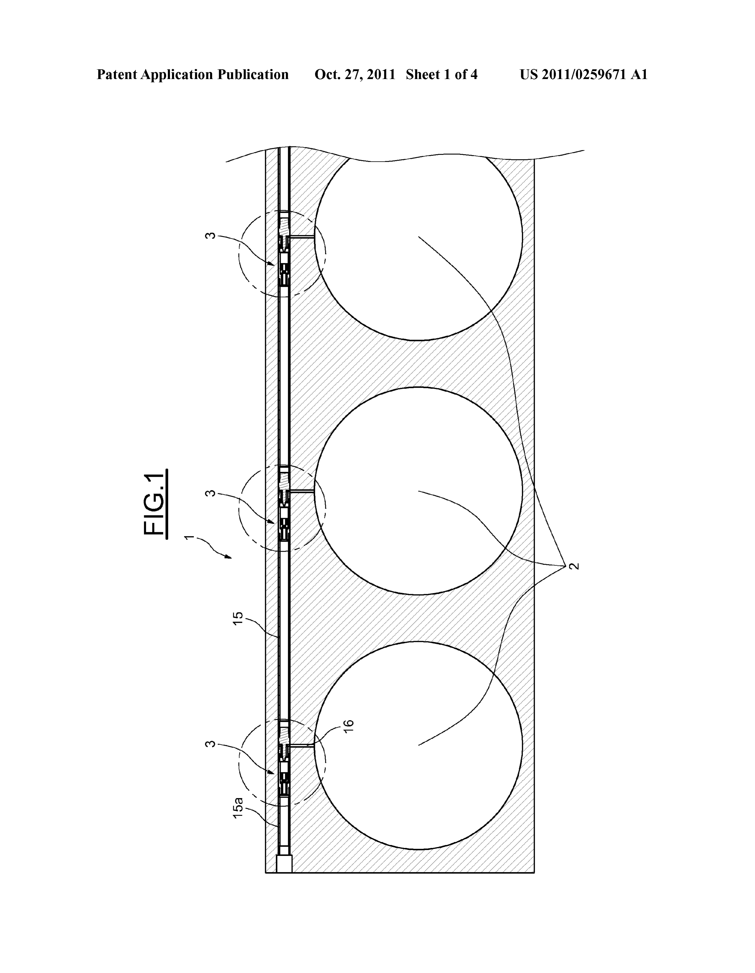
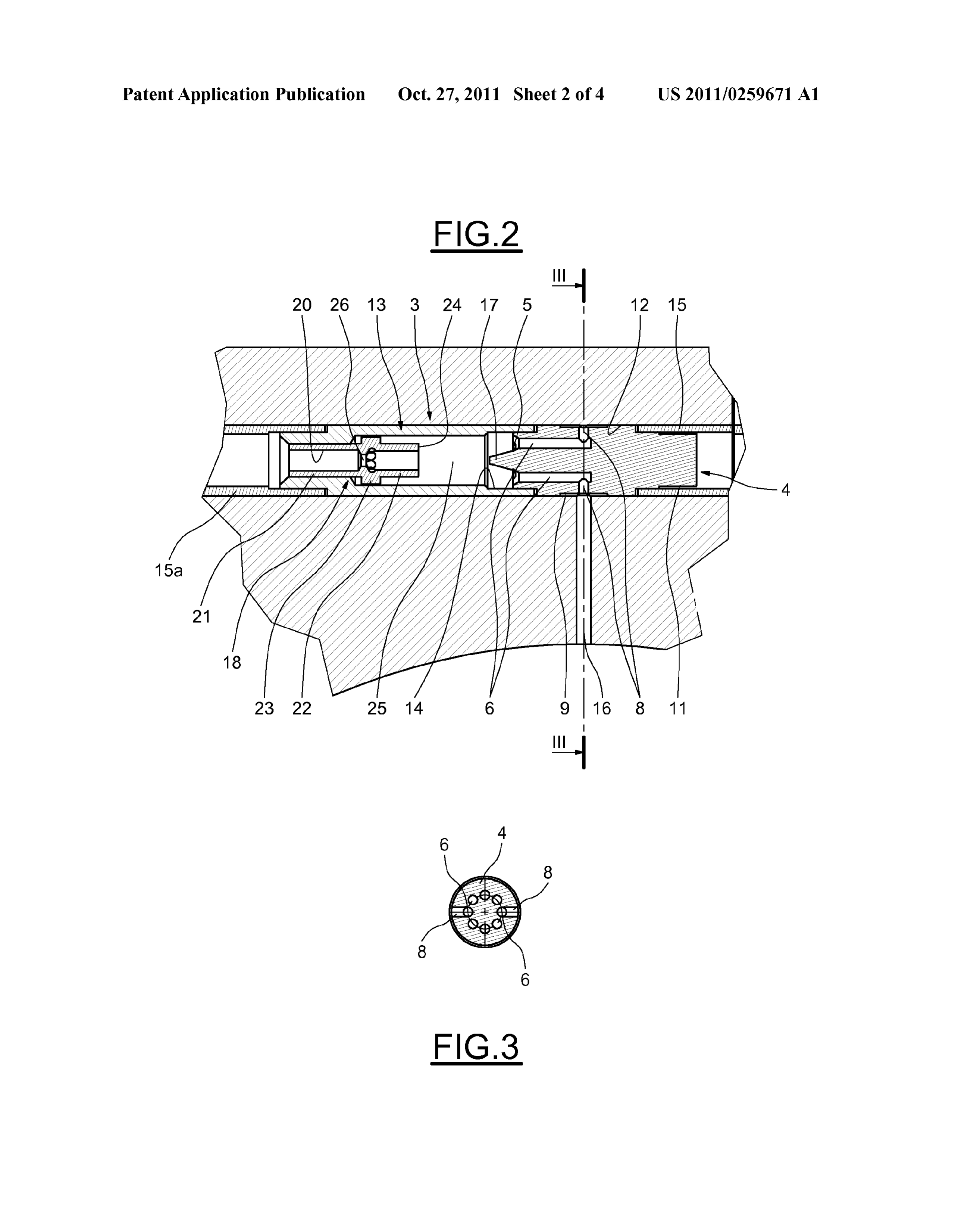
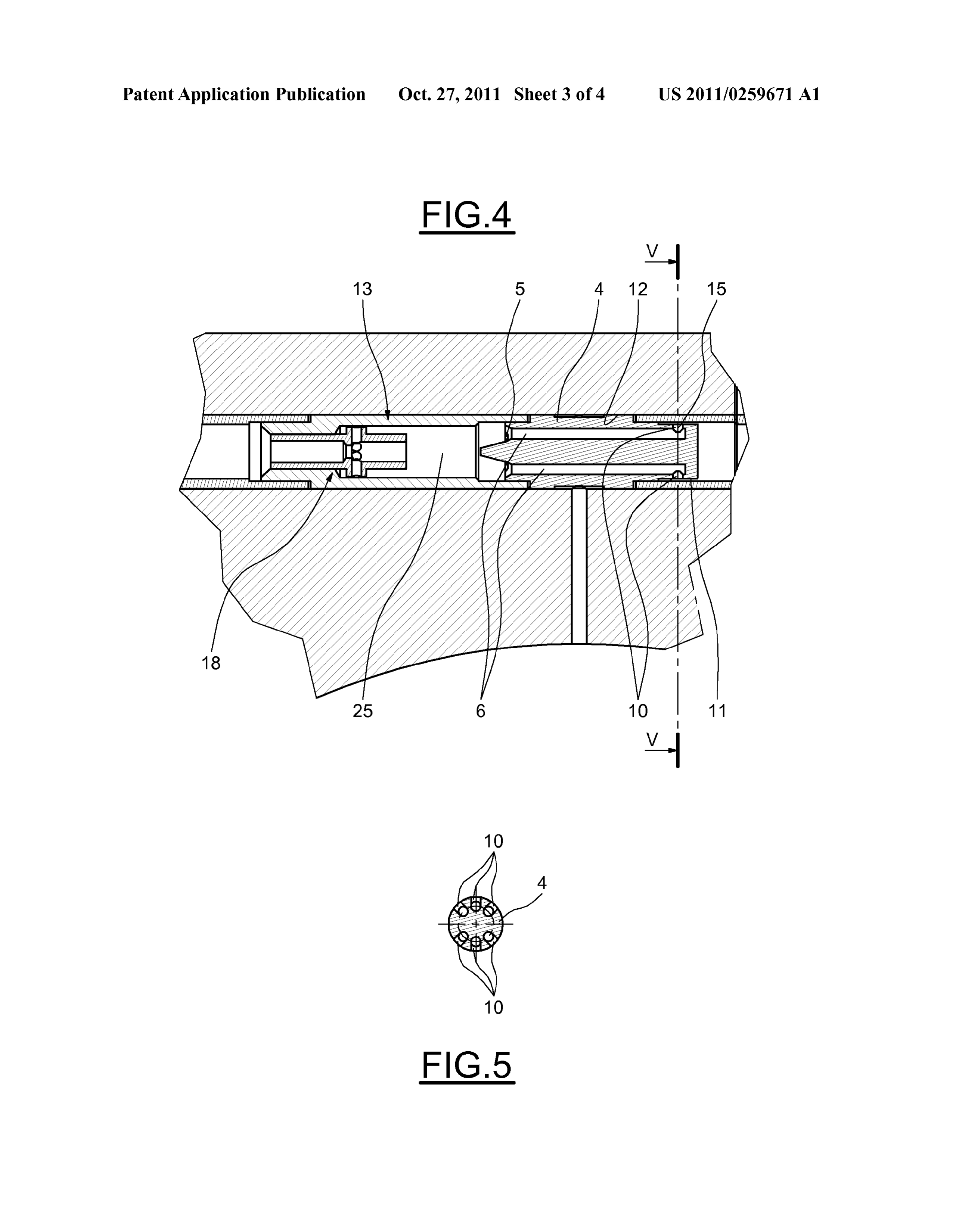
into minute droplets in the gas stream. German Utility Model 0014. The lubricant is thus atomized into fine droplets by Application 297 24492, which corresponds to U.S. Pat. No. the Venturi effect produced by the throttling region. The 6.257,370 (REBS), describes the use of a connection piece diameter of the lubricant droplets is around 1 to 100 microns. which has an angular region in a Supply bore followed by a The existence of the chamber increases the turbulence of the tapering funnel-shaped region defining a dispensing cham flow of the mixture of lubricant droplets and gas. The minute ber. Inside this chamber, lubricant droplets accumulate in atomized droplets then distribute themselves uniformly dead regions from where they are picked up by the gas stream. across the cross section of the chamber before striking the end A distribution barrel is coupled to the connection piece and face of the distribution barrel and passing into the longitudi comprises longitudinal channels which distribute the lubri nal distribution channels. The distribution of the lubricant cant/air mixture. across all the distribution channels is excellent, even if head 0004. A similar arrangement is found in German Utility losses are not identical in each distribution channel. Model Application 20 2007 005930 (REBS), which teaches 0015 The distribution barrel and the connection piece are the formation of turbulence in the supply stream by a funnel advantageously inserted in an assembly tube whose bore shaped part located in a connection piece coupled to a distri defines said chamber.
bution body. 0016 That part of the barrel which comprises the outlet 0005. In these devices, however, it is observed that the orifices may project from said assembly tube. lubricating mixture is not correctly distributed when the 0017. In a preferred embodiment, the divider device also backpressure downstream of the divider device is not the comprises means for the recirculation of lubricant that has not same in all the distribution channels. entered the distribution barrel and is in the aforementioned 0006. The same fault is found in a divider device described chamber.
in German Utility Model Application 20 2007 009472 (Lin 0018. The reason for this is that some of the lubricant stays coln), where the distribution between the different channels is in the chamber without entering one of the distribution chan effected by a conical piece which divides up the flow. Inter nels. The build-up of this lubricant in the chamber could spoil national Patent Application WO 2005/113 157 (REBS) the operation of the divider device. By continuously recircu attempts to improve the distribution of lubricant/air mixtures lating this lubricant and reusing it, this difficulty is solved. by creating a Swirling flow by having outlet orifices arranged 0019 For this purpose, the connection piece comprises radially. The aim is to create a helical Swirl in a dispensing preferably at least one radial passage passing through its wall, chamber located between a connection piece and a distribu communicating with said chamber, and opening into the tion barrel. The same type of construction is also found in localized throttling region or into the immediate vicinity of German Utility Model Application DE 203 11631 (Delimon), the latter.
which uses a Swirl chamber and an expansion chamber 0020. The connection piece may comprise multiple evenly between the supply and distribution of the lubricant/air mix distributed radial passages passing through its wall, commu ture.
nicating with said chamber, and opening into the localized 0007. These devices do not perform satisfactorily in prac throttling region or into the immediate vicinity of the latter. tice. Lubricant that stays in the chamber is thus sucked out by the 0008. Additionally, all known devices are found to work depression caused by the Venturieffect of the throttling of the defectively because of lubricant not being completely modi connection piece and is recycled into the stream of mixed fied in the distribution channels following the divider devices. lubricant and gas into the connection piece. This lubricant builds up inside the device and interferes with 0021. In one advantageous embodiment, the connection the operation of the divider. piece comprises an upstream tubular portion and a down 0009. It is an object of the present invention to improve the stream tubular portion, these two being separated from each divider devices of the prior art. other by an annular rib whose outside diameter is greater than
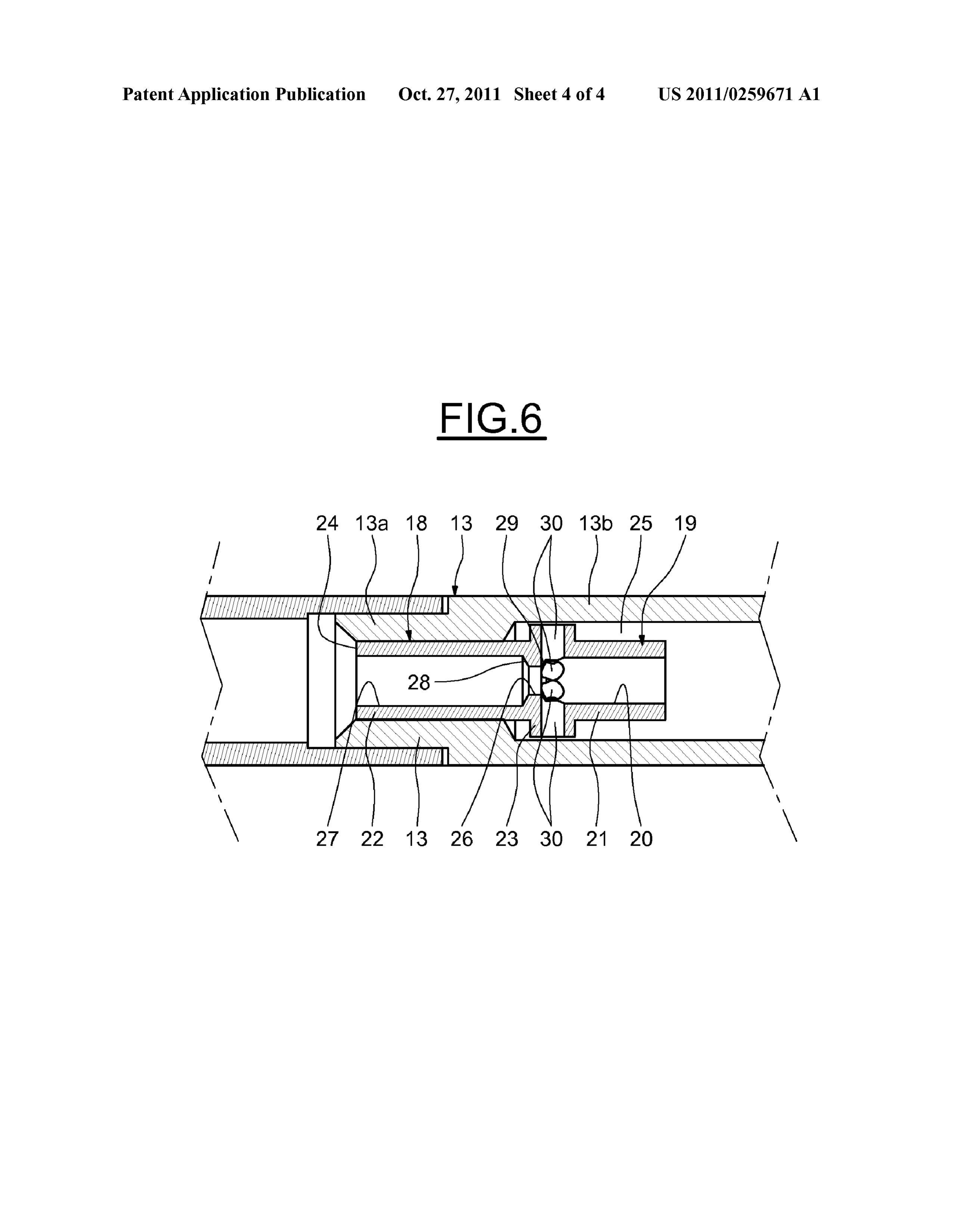
Page 7
US 2011/0259671 A1 Oct. 27, 2011
that of said tubular portions but less than that of the bore of the around the circumference of the barrel 4. The region 9 is assembly tube, through which annular rib the aforementioned situated in the approximate centre of the barrel 4. radial passage(s) pass. 0034. Other longitudinal channels 7, of which there are 6 0022. The upstream tubular portion of the connection in the example illustrated, are distributed symmetrically on piece may be force-fitted into the assembly tube, the down either side of the channels 6 and lead to outlet orifices 10 stream tubular portion and the annular rib being housed in the which take the form of radial passages leading to an annular chamber defined inside said assembly tube, and a radial play smaller-diameter region 11 at the far end of the distribution being left between the periphery of the annular rib and the barrel 4 from the end face 5. The distribution channels 7 bore of the assembly tube in said chamber. extend longitudinally further than the longitudinal channels 6 0023. In one embodiment, the distribution barrel has, on and end in the vicinity of the end of the barrel 4, as can be seen its end face, a projecting portion of generally conical shape in FIG. 4.
pointing towards the connection piece. 0035. The distribution barrel 4 is fitted inside a through 0024. The distribution barrel may advantageously com passage 12 formed in the actual thickness of the wall of the prise a first set of radial outlet orifices communicating with a chock 1. The distribution barrel 4 includes a central portion first set of longitudinal distribution channels, and a second set containing the annular Smaller-diameter region 9, but whose of radial outlet orifices communicating with a second set of outside diameter away from the said annular region 9 corre longitudinal distribution channels. The device can thus lubri sponds to the bore of the passage 12. The end of the barrel 4 cate a particular point and allow the flow of lubricant and gas containing the end face 5 is inserted into the end of an assem to be transferred to another lubrication point, optionally fitted bly tube 13, which in turn is installed inside the passage 12 in with another divider device of the same structure. the chock 1. That part of the barrel 4 which comprises the 0025. In another aspect, the invention provides a lubrica outlet orifices 8 and 10 projects from the assembly tube 13. tion system, particularly for chambers of multiple rolling The majority of the assembly tube 13 has an outside diameter contact bearings in rolling mills or levellers, with multiple equal to the inside diameter of the bore of the passage 12. points of lubrication from a centralized supply providing a Towards one of its ends, the assembly tube 13 has a portion flow of lubricant carried by a gas, typically air. The system where the bore 14 allows the end of the distribution barrel 4 to uses multiple divider devices as described above mounted in be inserted, by force So as to create a seal. series in a Supply passage, each divider device Supplying one 0036. The opposite end of the distribution barrel 4 from lubrication point and transferring to the next device the the end face 5 is inserted into a connection tube 15 which remaining flow of lubricant and gas. defines a passage for the air/lubricant mixture from a first 0026. The invention will be understood more clearly on divider device 3 to the next divider device 3, as can be seen in studying an embodiment taken as an example, without any FIG. 1 in particular. The connection tube 15 thus constitutes limitation being implied, illustrated in the appended draw a spacer defining, inside the passage 12, a precise gap ings, in which: between two divider devices 3. The outside diameter of the end of the distribution barrel 4 intended to be inserted into the 0027 FIG. 1 is a cross section through a multi-bearing assembly for a steel rolling mill fitted with lubricating devices end of the connection tube 15 is equal to the diameter of the according to the invention; bore of the connection tube 15, to create a leaktight fit. The 0028 FIG. 2 is an enlarged cross section on a first longi annular smaller-diameter region 11 at the end of the distribu tudinal plane through a divider device according to the inven tion barrel 4 thus defines a gap between the outer surface of tion, as used in the system shown in FIG. 1; this portion of the barrel 4 and the bore of the connection tube 15, and the orifices 10 communicate with this gap.
0029 FIG. 3 is a transverse cross section on III-III as 0037 Similarly, the annular smaller-diameter region 9 marked in FIG. 2; defines a peripheral groove around the distribution barrel 4 0030 FIG. 4 is a cross section on another longitudinal with which the orifices 8 communicate and which is also in plane through the same divider device; communication with a lubrication channel 16 connected to 0031 FIG. 5 is a transverse cross section on V-V as the recess 2 which corresponds to the divider device 3. The marked in FIG. 4; and lubrication channel 16 is preferably oriented radially with 0032 FIG. 6 is an enlarged cross section showing more respect to the circular-section recess 2 in order to minimize particularly the connection piece of a divider device accord the length between the divider device 3 and the recess 2 acting ing to the invention. as the bearing housing, which must be lubricated. 0033. As illustrated in FIG. 1, a multi-bearing assembly or 0038. The end face 5 of the distribution barrel 4 can be "chock” as it is also known, marked 1 as a whole, Supports a seen to have a projecting portion of generally conical shape, plurality of roller shafts mounted in the cylindrical recesses 2. marked 17, in the centre of the circle defining the end face 5, For each rolling-contact bearing (not illustrated in the figure) forming a spike leading in the opposite direction to the dis a lubrication seal comprises a divider device 3. This kind of tribution channels 6 and 7.
divider device, in one example of the invention illustrated in 0039. A connection piece 18 is installed in the flow of the FIGS. 2 to 5, comprises a distribution barrel 4 with an end face air/lubricant mixture, upstream of the distribution barrel 4 5 into which longitudinal distribution channels 6 and 7 inside the assembly tube 13. The connection piece 18 has a extend. These are distributed evenly around a peripheral hollow body with a bore 20 through which the lubricant/air region of the end face 5. In the example depicted, two distri flow from a central Supply (not shown in the figures) can pass. bution channels 6, visible in FIGS. 2 and 3, are positioned on The connection piece 18 comprises an upstream tubular por diametrically opposite sides and communicate with outlet tion 21 and a downstream tubular portion 22 (FIG. 6) sepa orifices 8 formed by radial passages, also diametrically rated from each other by an annular rib 23 whose outside opposed, which pass out of the distribution barrel 4 in an diameter is greater than that of the tubular portions 21 and 22. annular region 9 of Smaller diameter running all the way The connection piece 18 is fitted via its upstream tubular
Page 8
US 2011/0259671 A1 Oct. 27, 2011
portion 21 into a portion 13a of the assembly tube 13 which 0044 Some of the lubricant that strikes the end face 5 but has a bore whose diameter corresponds to the outside diam does not enter one of the longitudinal channels 6 and 7 drips eter of the tubular portion 21, to create a seal. The downstream into the bottom of the chamber 25. This lubricant is preferably tubular portion 22, like the annular rib 23, projects from the licked up and recirculated into the compressed air stream. The assembly tube 13 into a portion 13b of the latter where the radial passages 30 running through the annular rib 23 of the bore is greater than the outside diameter of the annular rib 23. connection piece 18 enable this lubricant to be recirculated. In this way a gap is left between the cylindrical peripheral The reason for this is that these radial passages 30 which have surface of the annular rib 23 and the bore of the portion 13b of open ends in the immediate vicinity of the throttling region 26 the assembly tube 13, as FIG. 6 shows. The downstream downstream or upstream thereof, or as a variant in this throt tubular portion 22 ends at an end face24 remote from the end tling region 26, are subjected to a Venturi effect which aspi face 5 of the distribution barrel 4 as FIGS. 2 and 4 show, in rates any lubricant in the chamber 25 through said channels order to define a chamber 25 between the connection piece 18 30, owing to the movement of the flow of compressed gas and and the distribution barrel 4. lubricant along the bore of the connection piece 18. Lubricant in the chamber 25 is licked up by the radial passages 30 and 0040. The bore of the distribution piece 18 has a localised re-injected into the compressed airstream, at the site of the throttling region 26 (FIG. 6). This is inside the annular rib 23 throttling region 26 or immediately upstream or downstream and it connects to the bore 20 of the upstream tubular portion of it. This lubricant is therefore atomized again before being 21 via a tapering portion 28 whose angle is, in the example returned to the chamber 25 where it can once again strike the illustrated, about 120°. The throttling region 26 opens into the end face 5.
bore 27 of the downstream tubular portion 22 through a taper 0045 Most of the mixture of atomized lubricant and com ing portion 29 whose angle is, in the example illustrated, also pressed air, after Striking the end face 5, passes into the about 120°. longitudinal distribution channels 6 and 7. The mixture con 0041 Radial passages 30, of which there are six in the veyed by the channels 6 passes out through the radial orifices example illustrated, pass through the wall and the connection 8 into the smaller-diameter region 9 and into the lubrication piece 18 at the site of the annular rib. 23. These evenly dis channel 16 of the recess 2 connected to the divider device 3. tributed radial passages 30 terminate in the tapering portion The rest of the mixture of lubricant and compressed air con 29 in the immediate vicinity of the throttling region 26 down veyed by the longitudinal channels 7 passes out through the stream thereof, in the bore of the connection piece 18. On the radial orifices 10 situated downstream of the distribution bar outside, the radial passages 30 open into the gap between the rel 4. The mixture of compressed air and lubricant is then cylindrical surface of the annular rib 23 and the bore 13b of taken up by the connection tube 15 and conveyed to the next the assembly tube 13. The radial passages thus communicate divider device 3 connected to the next recess 2. In this second with the chamber 25. divider device 3, the same atomizing process takes place for the same reasons.
0042. As FIGS. 1 and 2 show, the assembly tube 13 is inserted, via its end containing the connection piece 18, into 0046 By using multiple divider devices 3 positioned in the bore of a connection tube 15a. It is a force fit to prevent series along a given passage 12 of the chock 1, it will be seen leaks. that the result is a lubrication system with multiple lubrication 0043. The divider device described above works in the points connected to a centralised Supply. The present inven following way: a mixture of compressed air at a pressure that tion achieves excellent distribution of lubricant, even though may be between 2 and 8 bar, and lubricant, is delivered by the the backpressure varies depending on the position of the connection tube 15a situated furthest upstream, having various divider devices and the position of the outlet orifices of the various distribution channels inside each of the divider arrived from a centralized Supply (not shown in the figures). devices. It will be seen that the inside diameters of the distri This mixture enters the first divider device 3 by flowing along bution channels 6 and 7, and the structure of the orifices 8 and the bore 20 of the upstream tubular portion 21 of the connec 10, are preferably practically identical in order to maintain an tion piece 18. The throttling region 26, in combination with almost unvarying head loss.
the tapering portions 28 and 29, forms inside the bore of the 0047 Although the invention has been described chiefly in connection piece 18 a Venturi which creates turbulence in the relation to its use in a rolling mill, it will be understood that it flow which atomizes the lubricant. A multitude of minute droplets is thus formed as the flow passes through the throt can also be used in other industrial fields such as papermak tling region 26 and is carried into the chamber 25 before ing, in order to correctly lubricate the rolling-contact bearings striking the end face 5. This atomizing action of the throttling of papermaking machines.
region, and the even distribution of the resulting minute drop 0048. The invention can also be used to lubricate the lets of lubricant throughout the surface area of the end face5, flanges of the wheels of railway vehicles or any other rotating member in a vehicle.
due to the path set up along the chamber 25, makes for an excellent distribution of lubricant in finely atomized form inside the distribution barrel 4. The mixture of lubricantatom 1. A divider device for a flow of lubricant carried by a gas, ized in this way within the air flow is distributed evenly the divider device comprising:
regardless of any loss of head due to the length and path of the a distribution barrel having an end face, a plurality of outlet various lubrication passages downstream of the divider orifices spaced from the end face, and longitudinal dis device 3. The existence of the throttling region 26 in combi tribution channels extending from the end face and com nation with the chamber 25 thus brings about an excellent municating with the outlet orifices, and distribution of atomized lubricant regardless of head losses a connection piece mounted upstream of the distribution downstream. The existence of the projecting portion 17 is also barrel such that a chamber is defined in a gap between advantageous as it encourages the distribution of the mixture the barrel and the connection piece, the barrel including of atomized lubricant and compressed air. a hollow body with a bore through which passes the flow
Page 9
US 2011/0259671 A1 Oct. 27, 2011
of lubricant and gas, the bore having a localized throt inside the assembly tube such that radial clearance space is tling region of reduced cross section and a region of defined in the chamber between the outer periphery of the enlarged cross section. annular rib and the bore of the assembly tube. 2. The divider device according to claim 1, further com 9. The divider device according to claim 1, wherein the prising an assembly tube having a bore, the distribution barrel distribution barrel a generally conical-shaped projecting por and the connection piece being disposed within the assembly tion extending from the barrel end face and generally towards tube such that the tube bore partially defines the chamber. the connection piece.
3. The divider device according to claim 2, wherein the 10. The divider device according to claim 1, wherein the distribution barrel has a first set of the outlet orifices commu outlet orifices are disposed in a part of the barrel which nicating with a first set of the longitudinal distribution chan projects from the assembly tube. nels and a second set of the outlet orifices communicating 4. The divider device according to claim 2, further com with a second set of the longitudinal distribution channels. prising means for the recirculation of lubricant disposed 11. A lubrication system for lubricating chambers of mul within the chamber and externally of the distribution barrel. tiple rolling-contact bearings in rolling mills or levellers, with 5. The divider device according to claim 4, wherein the multiple points of lubrication from a centralized supply pro connection piece includes a wall and at least one radial pas viding a flow of lubricant carried by a gas, the system com sage extending through the wall, communicating with the prising:
chamber, and opening into one of the localised throttling a Supply passage and region and an immediate vicinity of the throttling region. a plurality of dividers disposed within the Supply passage 6. The divider device according to claim 5, wherein the and each Supplying lubricant to a separate one of the connection piece has a plurality of the radial passages spaced lubrication points, each divider including: circumferentially around the wall. a distribution barrel having an end face, outlet orifices 7. The divider device according to claim 4, wherein the spaced from the end face, and longitudinal distribu connection piece includes an upstream tubular portion, a tion channels extending from the end face and com downstream tubular portion, and an annular rib separating the municating with the outlet orifices, and upstream and downstream tubular portions, the rib having an a connection piece mounted upstream of the distribution outside diameter greater than an outside diameter of each barrel such that a chamber is defined in a gap between tubular portion and less than an inside diameter of the bore of the barrel and the connection piece, the barrel includ the assembly tube, the at least one radial passage extending ing a hollow body with a bore through which passes through the rib. the flow of lubricant and gas, the bore having a local 8. The divider device according to claim 7, wherein the ized throttling region of reduced cross section and a upstream tubular portion of the connection piece is force region of enlarged cross section. fitted into the assembly tube, the downstream tubular portion c c c c c and the annular rib being housed in the chamber defined
Provenance
- Collection
- Patents citing this work
- Current assignee
- SKF AB
- Pages
- 9
- Method
- pdftotext (the PDF's own text layer) + pdftoppm 300dpi page scans
- Patent office record
- patents.google.com →
- Source
- Google Patents citing-documents table
- Inventors
- Guillaume Amilien; Régis Page
- Published
- 2011-10-27
- Transcribed from
- patentimages.storage.googleapis.com →