patent · US5921349
Oil air lubricating apparatus
13 July 1999
Page 1 — bibliographic record
United States Patent (19) 11 Patent Number: 5,921,349 Sato et al. (45) Date of Patent: Jul. 13, 1999 54) OIL AIR LUBRICATING APPARATUS 4,359,141 11/1982 Schnell ................................... 184/6.26 5,253.733 10/1993 Miyachi ................................. 184/6.26 75 Inventors: Yukio Sato; Fumio Toyama; Yasushi
Amano, all of Kanagawa, Japan FOREIGN PATENT DOCUMENTS
WO 97/46825 12/1997 WIPO ............................... F16N 7/32 73 Assignee: NSK Ltd., Tokyo, Japan
Primary Examiner John A. Jeffrey 21 Appl. No.: 09/162,503 ASSistant Examiner David Fenstermacher Attorney, Agent, or Firm Sughrue, Mion, Zinn, Macpeak 22 Filed: Sep. 29, 1998 & Seas, PLLC 30 Foreign Application Priority Data 57 ABSTRACT Sep. 29, 1997 JP Japan .................................... 2: An oil air distributor is inserted in the inside of a support Aug. 28, 1998 JP Japan .................................. ' hole provided in a housing. The oil air distributoris designed 51 Int. Cl. ................................ F01M 1/00; F16N 7/30 So that outer pipes and a Spacer fitted onto an inner pipe are 52 U.S. Cl. ........................ 184/6.14; 184/55.1; 384/468; held, through Seal rings, between a flange portion provided 384/322 in the inner pipe and a Supply plug. In a condition in which 58 Field of Search .................................. 184/6.14, 55.1, the Seal rings are compressed axially, the Second oil-supply 184/6, 6.26, 81; 137/109, 118.01; 384/473, hole provided in the Supply plug is communicated with 468, 322 branch passages provided in the housing. Further, a plurality of inner-pipe-Side Small holes provided in the inner pipe are 56) References Cited opened Substantially horizontally in Vertically even-level positions.
3,618,709 11/1971 Boelkins .................................. 184/6.4 8 Claims, 9 Drawing Sheets
- 24 34 29 28 24 26 17 24 A - 2924
2^ / // / / C/ 414 taxatawarenewawwasse zyzy
77N, z // (4.g.Q
Page 2
Drawing sheet — no readable text.
Page 3
Drawing sheet — no readable text.
Page 4
Drawing sheet — no readable text.
Page 5
Drawing sheet — no readable text.
Page 6
Drawing sheet — no readable text.
Page 7
Drawing sheet — no readable text.
Page 8
Drawing sheet — no readable text.
Page 9
Drawing sheet — no readable text.
Page 10
Drawing sheet — no readable text.
Page 11
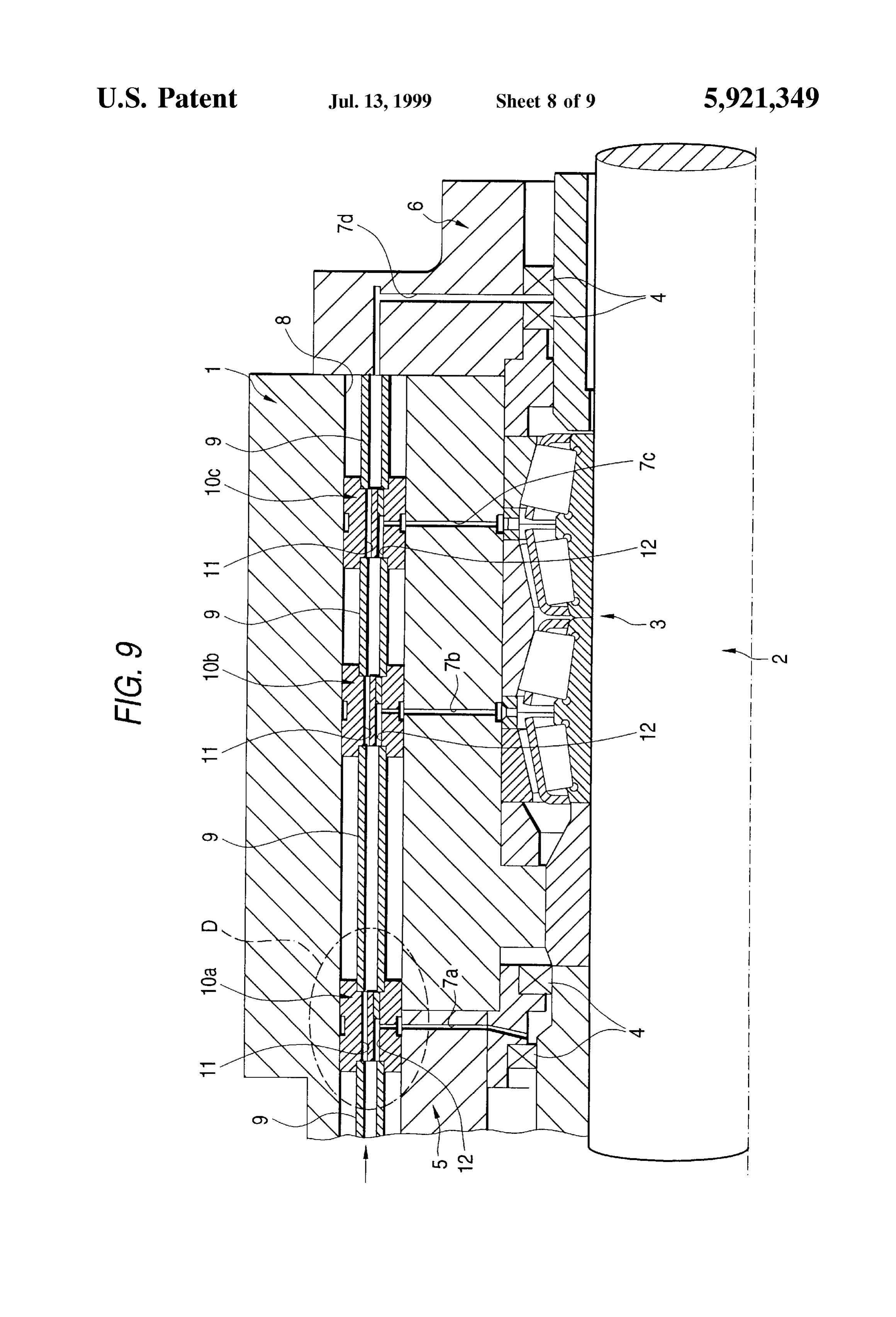
OIL AIR LUBRICATING APPARATUS distributors 10a, 10b and 10c are disposed in the inside of the Support hole 8, other-end openings of the Second
BACKGROUND OF THE INVENTION through-holes 12 are matched with other-end openings of 1. Field of the Invention the branch passages 7a, 7b and 7c, respectively. The first The present invention relates to an oil air lubricating through-hole 11 provided in the most downstream side apparatus, and particularly to an oil air lubricating apparatus distributor 10c is communicated with the branch passage 7d opened in the rear end Surface of the Support hole 8.
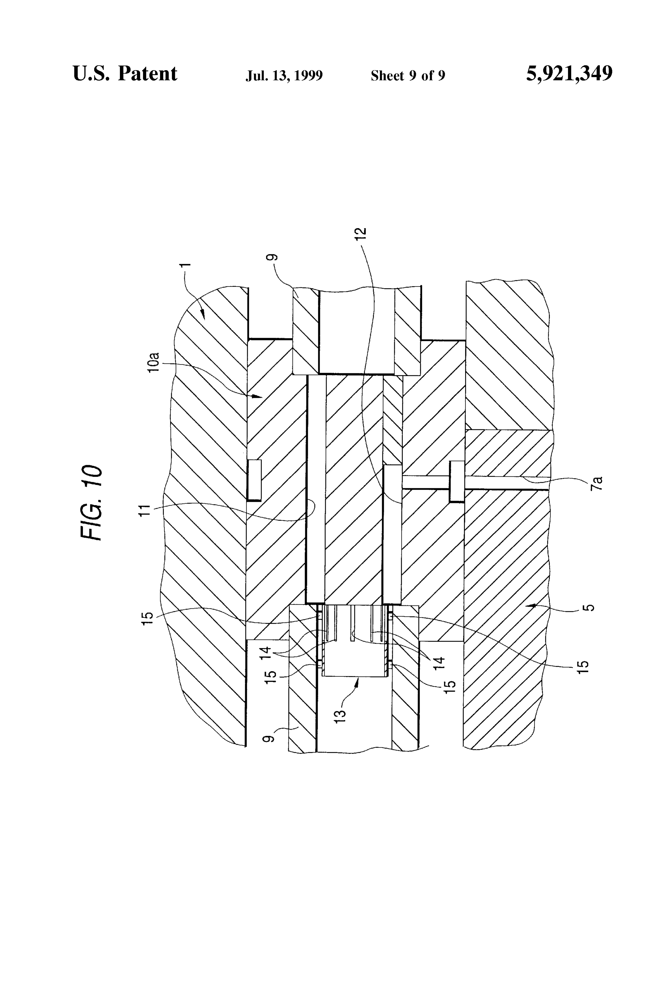
for carrying lubricating oil, by air, into the inside of rolling Further, cylindrical sleeves 13 are disposed, as shown in bearings for rotatably Supporting a high-Speed rotating shaft FIG. 10, in portions inside the circular-pipe-like oil supply Such as a main Shaft of a machine tool, or the like. passages 9, 9 and just prior to the distributors 10a, 10b and 2. Description of the Related Art 10c respectively. Each of the sleeves 13 has a plurality of A machine-tool main Shaft rotates at a high Speed in use. Slits 14, 14 arranged circumferentially, and a plurality of Accordingly, not only a main shaft of this type is required to protrusions 15, 15 provided so as to be protruded from the be rotatably Supported by rolling bearings but also a required outer circumferential Surface of the sleeve 13. In the con minimum quantity of lubricating oil is necessary to be 15 dition in which the sleeves 13, 13 are fitted into the circular accurately Supplied to the inside of the rolling bearings when pipe-like oil Supply passages 9, 9 respectively, cylindrical the main Shaft rotates. AS an apparatus for Supplying lubri fine gaps are formed between the outer circumferential cating oil to the inside of each rolling bearing in the Surfaces of the sleeves 13, 13 and the inner circumferential aforementioned manner, an oil air lubricating apparatus Surfaces of the circular-pipe-like oil Supply passages 9, 9 by conventionally known is configured Such that lubricating oil the presence of the protrusions 15, 15. is fed into the inside of a Supply passage So as to be carried According to the oil air lubricating apparatus disclosed in through the Supply passage by air So that the lubricating oil Japanese Patent Publication No. Hei. 5-340499 and config is Supplied to a plurality of portions to be lubricated through ured as described above, lubricating oil discharged from the a plurality of branch passages branched from the aforemen not-shown oil Supply Source can be distributed, in a proper tioned Supply passage. AS Such an oil air lubricating 25 quantity each time, to the branch passages 7a, 7b, 7c and 7d apparatus, for example, known are those disclosed in Ger and to portions to be lubricated which are communicated man Patent No. 2844995 and Japanese Patent Publication with the branch passages 7a, 7b, 7c and 7d through the No. Hei. 5-340499. In those oil air lubricating apparatuses, circular-pipe-like oil Supply passages 9, 9 and the distribu a proper quantity of lubricating oil can be Supplied to tors 10a, 10b and 10c, respectively. Further, because cylin portions to be lubricated without being affected by the drical fine gaps are formed in portions just prior to the gravity. FIG. 9 shows the oil air lubricating apparatus distributors 10a, 10b and 10c by the presence of the sleeves disclosed in Japanese Patent Publication No. Hei. 5-340499 13, lubricating oil flowing in the fine gaps is spread circum as one of those known oil air lubricating apparatuses. ferentially by capillarity even in the case where the quantity The oil air lubricating apparatus disclosed in Japanese of lubricating oil flowing in the circular-pipe-like oil Supply Patent Publication No. Hei. 5-340499 is designed to supply 35 passages 9, 9 is So Small that the lubricating oil is reserved lubricating oil to respective portions to be lubricated, that is, in lower portions of the circular-pipe-like oil Supply pas multi-row tapered roller bearing 3 for Supporting a rotation Sages 9, 9 by the influence of the gravity. Accordingly, shaft 2 So as to be rotatable relative to a housing 1, and proper quantities of lubricating oil can be distributed to the contact-type oil Seal 4, 4 provided on axially opposite sides first and Second through-holes 11 and 12 respectively. of the tapered roller bearing 3. This lubricating oil is of an 40 Though not shown, German Patent No. 2844995 discloses oil air type in which lubricating oil is carried, by air, from a an oil air lubricating apparatus in which a proper quantity of not-shown oil Supply Source to the aforementioned portions lubricating oil fed into a distributor communicated with one to be lubricated. To this end, a plurality of branch passages oil Supply passage is distributed to a portion to be lubricated 7a, 7b, 7c and 7d are provided in the housing 1, a collar 5 and the residual quantity of lubricating oil is distributed to fixedly connected to the housing 1, and a cover 6, and the 45 the next distributor. In the structure disclosed in German respective one ends (lower ends in FIG. 9) of the plurality Patent No. 2844995, therefore, a plurality of first interme of branch passages 7a, 7b, 7c and 7d are communicated with diate passages to be communicated with portions to be the aforementioned portions to be lubricated correspond lubricated and a plurality of Second intermediate passages to ingly. Among the branch passages 7a, 7b, 7c and 7d, the be communicated with next distributors are opened alter other ends (upper ends in FIG. 9) of the branch passages 7a, 50 nately in places arranged circumferentially in the inner 7b and 7c are opened in lower portions of the inner circum circumferential Surface of the distributor communicated ferential Surface of a Support hole 8 provided in the housing with the oil Supply passage. According to the oil air lubri 1 while the residual branch passage 7d is opened in the rear cating apparatus disclosed in German Patent No. 2844995 end surface of the Support hole 8. and configured as described above, proper quantities of A plurality of circular-pipe-like oil Supply passages 9, 9 55 lubricating oil can be distributed without imbalance in any and a plurality of distributors 10a, 10b and 10c are inserted intermediate passage even in the case where the quantity of in the inside of the Support hole 8, and the plurality of lubricating oil fed to the distributor is so small that the circular-pipe-like oil Supply passages 9, 9 and the plurality lubricating oil is reserved in the lower portion of the of distributors 10a, 10b and 10c are arranged axially serially distributor by the influence of the gravity. and alternately So that the inner portions of the passages 9, 60 In the oil air lubricating apparatuses disclosed in the 9 and distributors 10a, 10b and 10c are communicated with Japanese Patent Publication No. Hei. 5-340499 and German one another. Further, each of the distributors 10a, 10b and Patent No. 2844995, a complex structure is required in order 10c has a first through-hole 11 for communicating axially to Supply proper quantities of lubricating oil to portions to be opposite end Surfaces with each other, and a Second through lubricated respectively. Accordingly, increase in production hole 12 for communicating one end with one axial end 65 cost cannot be avoided. Further, in the case where the surface (left end surface in FIG.9) and the other end with the number of portions to be lubricated is not smaller than three, outer circumferential Surface. In the condition in which the distributors not smaller than two are required. Further, while
Page 12
the distributors are assembled in the inside of the support grooves being formed at positions axially apart from the hole provided in the housing, it is necessary to make the recessed grooves on the Outer peripheral Surface of the inner positions of openings of the branch passages provided in the pipe over all periphery in place of the outer pipes, wherein Support hole and the positions of oil-discharge openings of a plurality of the annular Sealing members are fitted into the the distributors coincident with each other. Accordingly, not Seal grooves and the inner pipe is inserted into the Support only an exclusive-use jig for assembling the distributors is hole, and wherein with the holding means connected to the required but also the labor required for the assembling work opening end portion of the Support hole, the Sealing mem is considerably troublesome. bers are compressed diametrically between the bottom Sur faces of the Seal grooves and the inner circumferential
SUMMARY OF THE INVENTION 1O Surface of the Support hole and the inner-pipe-Side Small
It is an object of the present invention to eliminate the holes and the branch passages defined in the housing are aforementioned disadvantages and to provide an oil air made to communicate with each other.
lubricating apparatus in which proper quantities of lubricat In the oil air lubricating apparatus configured as described ing oil can be distributed while both the cost of parts and 15 above according to the present invention, constituent mem labor required for assembling work are reduced. bers of an oil air distributor can be handled collectively in a In order to achieve the above object, according to the state in which the members are assembled into one body even in the case where the number of portions to be Supplied present invention, the oil air lubricating apparatus com with lubricating oil is not Smaller than three. Accordingly, prises: (1) a housing provided with a Support hole; (2) a the apparatus is simplified in Structure, So that the cost of the plurality of branch passages formed in an inside of the apparatus is reduced.
housing, the branch passages having respective one ends nicated with a Second That is, an oil Supply Source commu oil-Supply hole provided in the Supply opened in axially Separate positions in an inner circumfer plug can communicate with portions ential Surface of the Support hole and respective other ends through a plurality of branch passageS toprovided be lubricated in the communicated with portions to be lubricated respectively; housing Simply by an operation in which an oil air distribu and (3) an oil air distributor provided in an inside of the 25 including a plurality of outer pipes and Sealing members Support hole; the oil air distributor including: (3a) an inner tor pipe having a pipe portion provided with a first oil-Supply fitted hole onto an inner pipe is inserted in the inside of a Support provided in the housing and the Sealing members are hole formed in an inside of the pipe portion, the pipe portion compressed between the Supply plug and a flange portion. being opened in one end Side thereof, the inner pipe being Accordingly, no exclusive-use jig and complex labor are inserted into the inside of the Support hole; (3b) a plurality required for the assembling work of inner-pipe-Side Small holes provided in an intermediate tioned communication State. Further,toinSecure the aforemen portion of the pipe portion and formed in axially Separate apparatus according to the present invention, air the oil lubricating
positions respectively So as to communicate inner and outer side Small holes are opened Substantially horizontally in circumferential Surfaces of the pipe portion with each other; Vertically even-level positions in the inner circumferential (3.c) a plurality of cylindrical outer pipes fitted onto the pipe 35 Surface of the first oil-Supply hole, lubricating oil can be fed portion and inserted into the inside of the Support hole; (3d) into the inner-pipe-side Small holes uniformly even in the outer-pipe-Side Small holes for communicating outer cir case where lubricating oil is reserved in the lower portion of cumferential Surfaces of the Outer pipes with bottom Sur the inside of the first oil-supply hole by the influence of the faces of recessed grooves formed in axially intermediate gravity.
portions of inner circumferential Surfaces of the outer pipes 40 respectively; (3f) a plurality of annular Sealing members Further, the oil air lubricating apparatus preferably com fitted onto part of the pipe portion and located in positions prises a plurality of recessed grooves and a plurality of Seal axially separated from the outer pipes respectively, (3g) grooves on the outer peripheral Surface of the inner pipe in means for holding (3a) to (3f) members in the inside of the place of the Outer pipes. Thus, the number of the parts of the Support hole (a Supply plug separate from the inner pipe, or 45 oil air distributor can be reduced, the inner pipe forming a a Supply plug portion integral with the inner pipe) holding part of the oil air distributor can be manufactured at low means having a connection portion which is connectable to decreased. costs, and moreover the number of fitting Steps can be an opening end portion of the Support hole and a Second oil-Supply hole which makes axially opposite end Surfaces BRIEF DESCRIPTION OF THE DRAWINGS with each other. 50
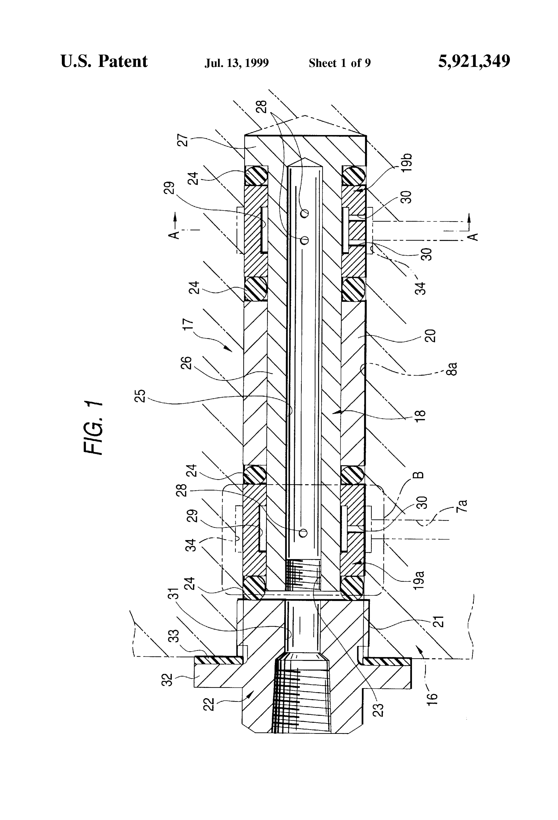
In the above oil air lubricating apparatus, inner and outer In the accompanying drawings:
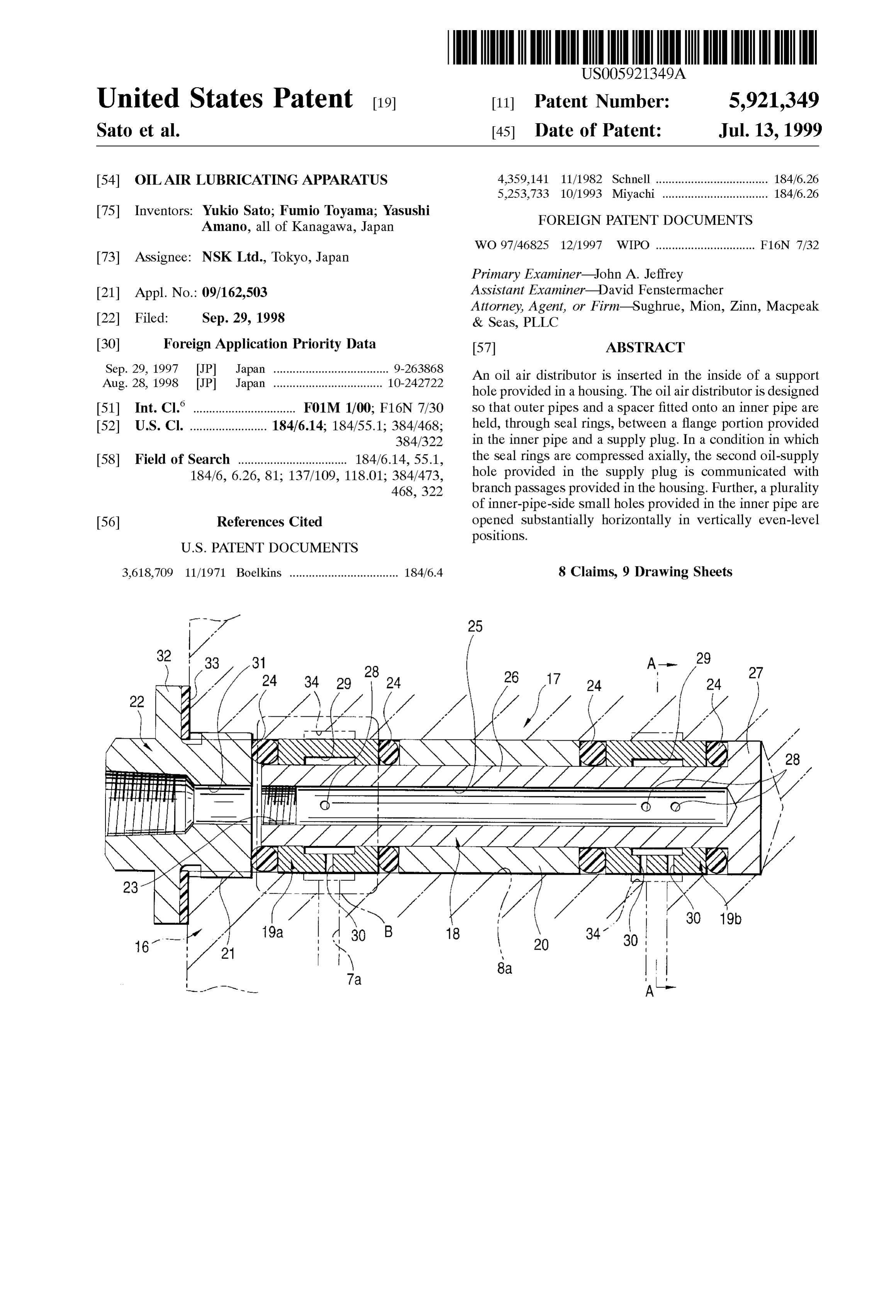
fringes of the annular Sealing members are elastically abut FIG. 1 is a sectional view showing a first embodiment of ted against the inner circumferential Surface of the Support the present invention;
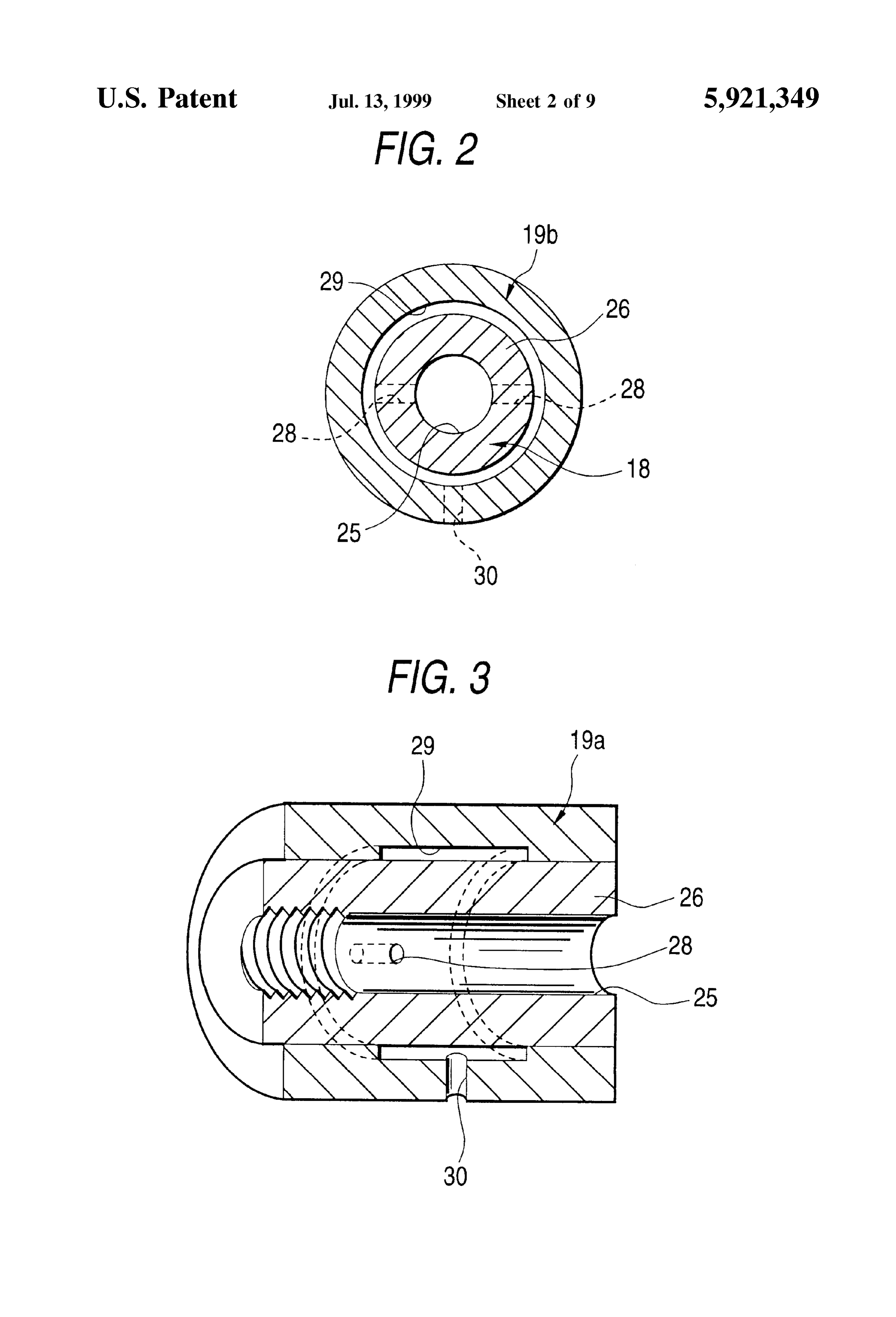
hole and an outer circumferential Surface of the inner pipe FIG. 2 is a Sectional view taken along the line A-A in are respectively inner over all Surfaces in a condition in 55 FIG. 1;
which the holding is connected to the opening end portion of FIG. 3 is a half-cutaway perspective view showing only the Support hole, So that the first oil-Supply hole and the the portion B taken out from FIG. 1;
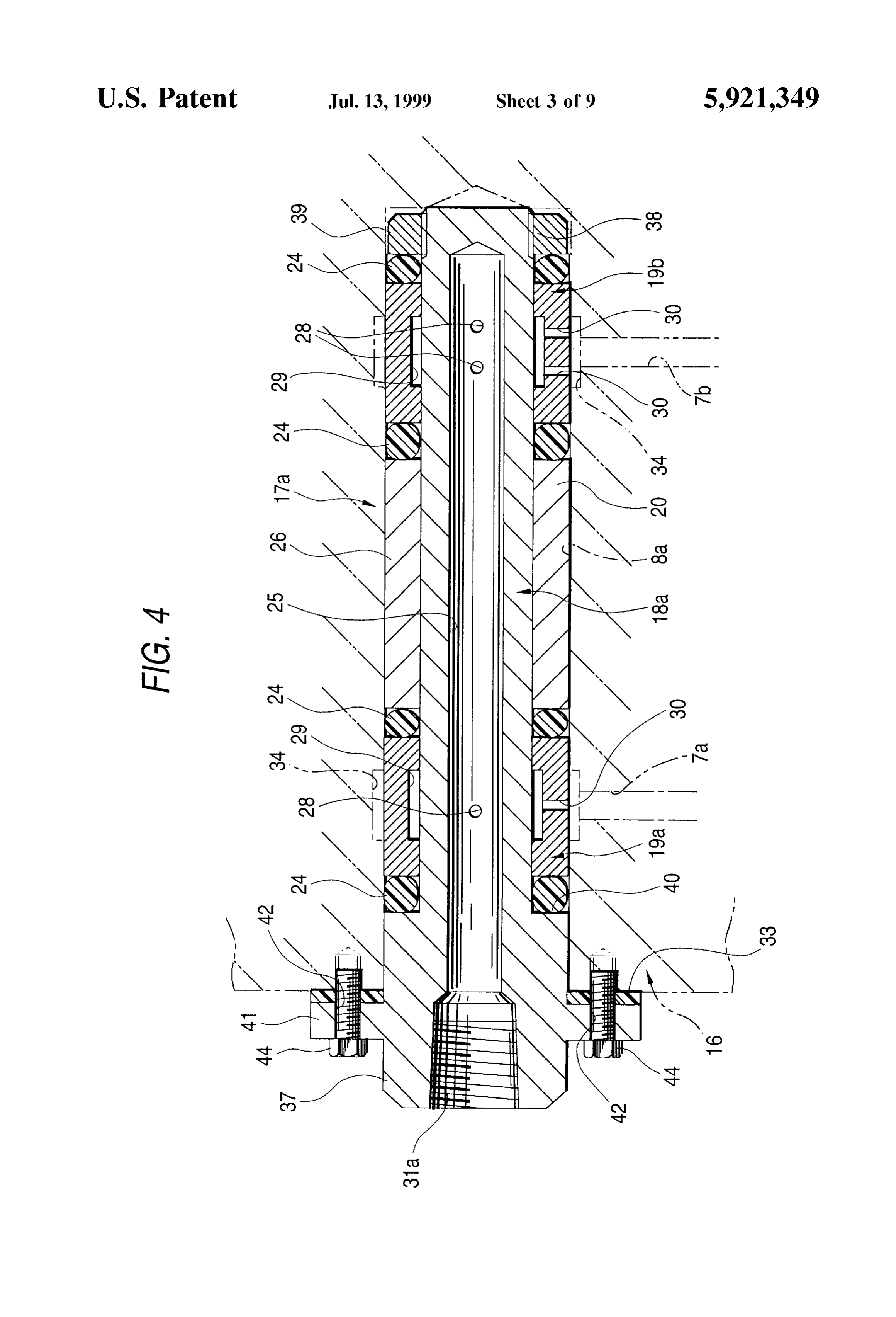
Second oil-Supply hole are communicated with each other, the inner-pipe-Side Small holes and the outer-pipe-Side Small of FIG. 4 is a Sectional view showing a Second embodiment holes are communicated with each other, and the outer-pipe 60 the present invention;
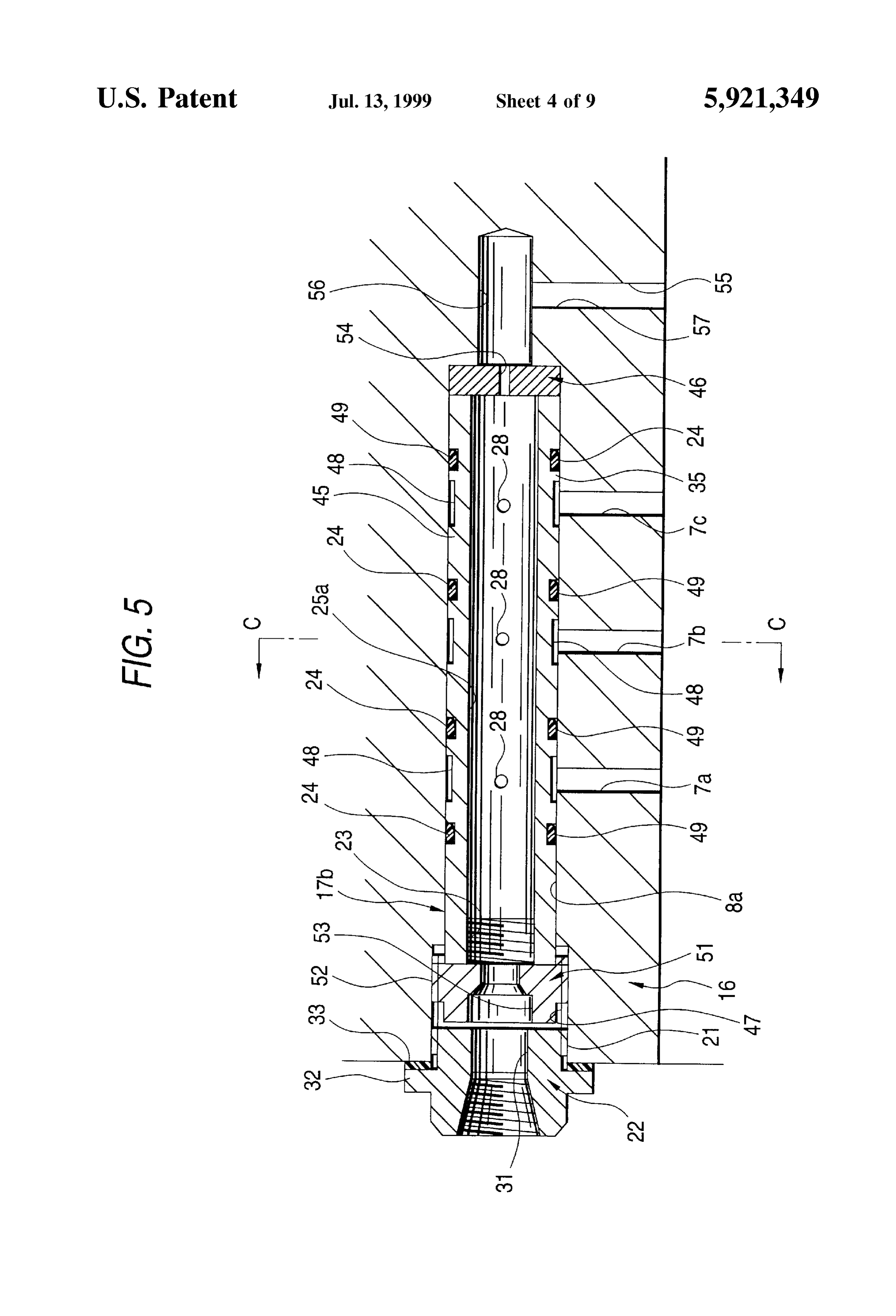
Side Small holes and the branch passages provided in the FIG. 5 is a sectional view showing a third embodiment of housing are communicated with each other. the present invention;
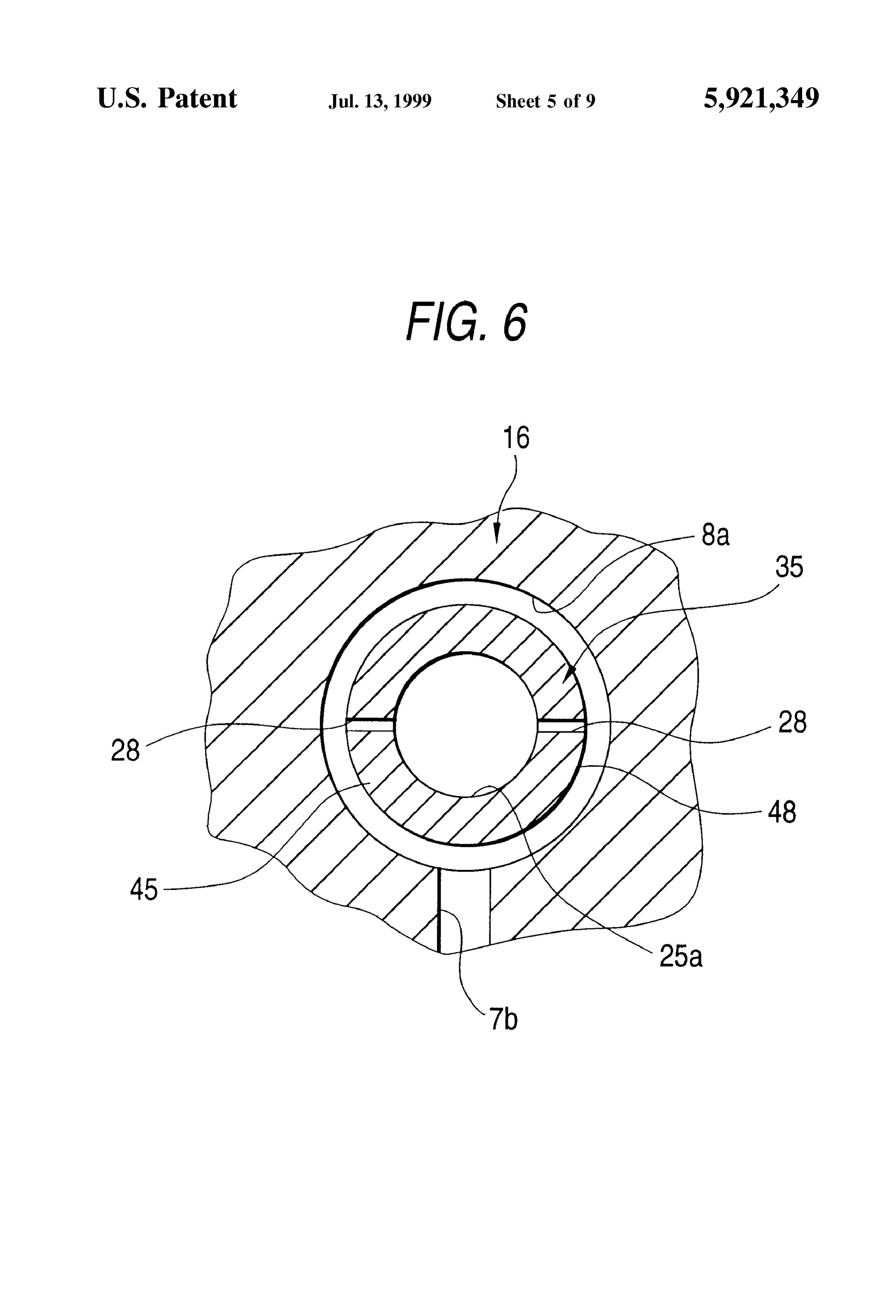
Further, the oil air distributor preferably further comprises FIG. 6 is a sectional view taken along the line C-C in a plurality of recessed grooves being formed at axially FIG. 1;
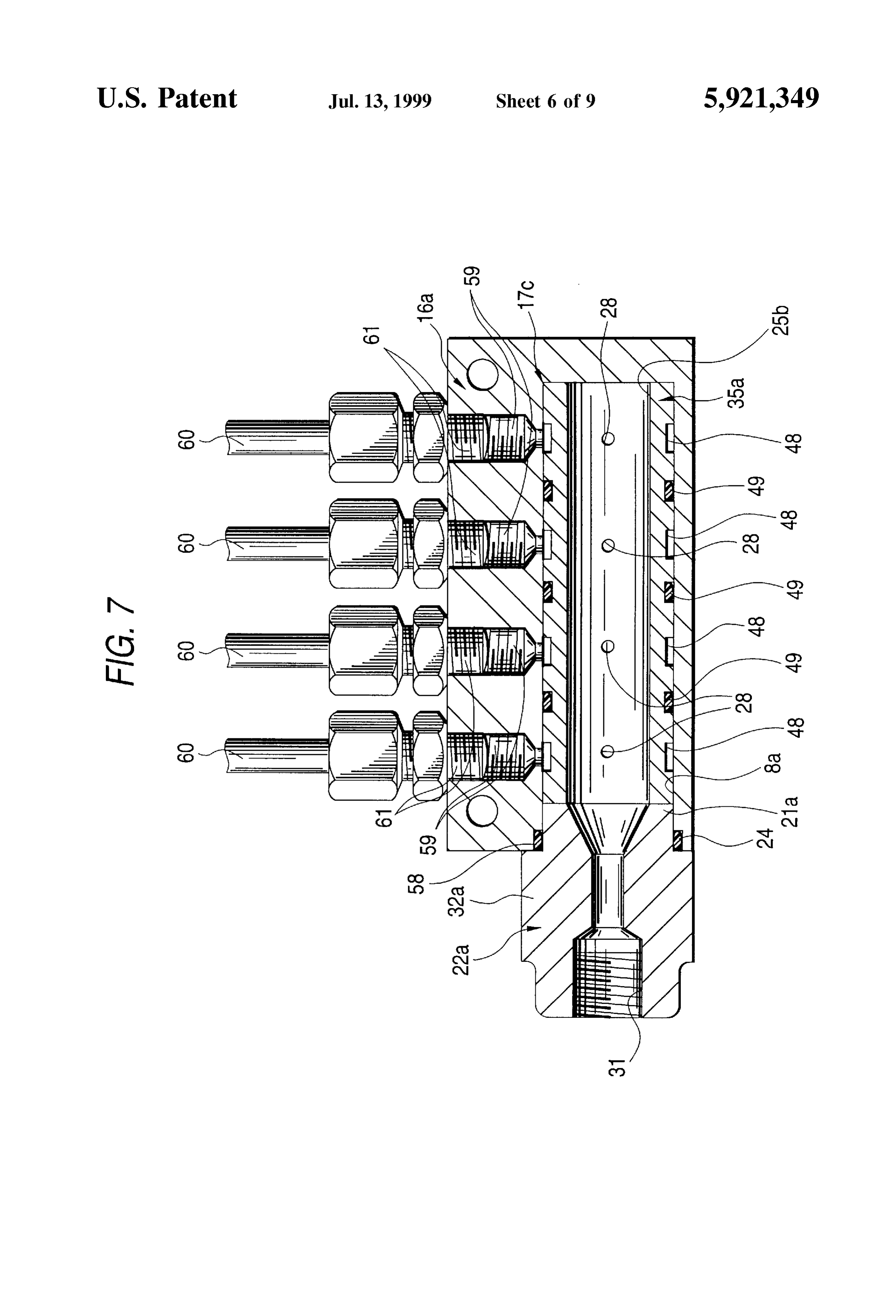
different positions on the outer circumferential Surface of the 65 FIG. 7 is a sectional view showing a fourth embodiment inner pipe and having bottom Surfaces made to communicate of the present invention;
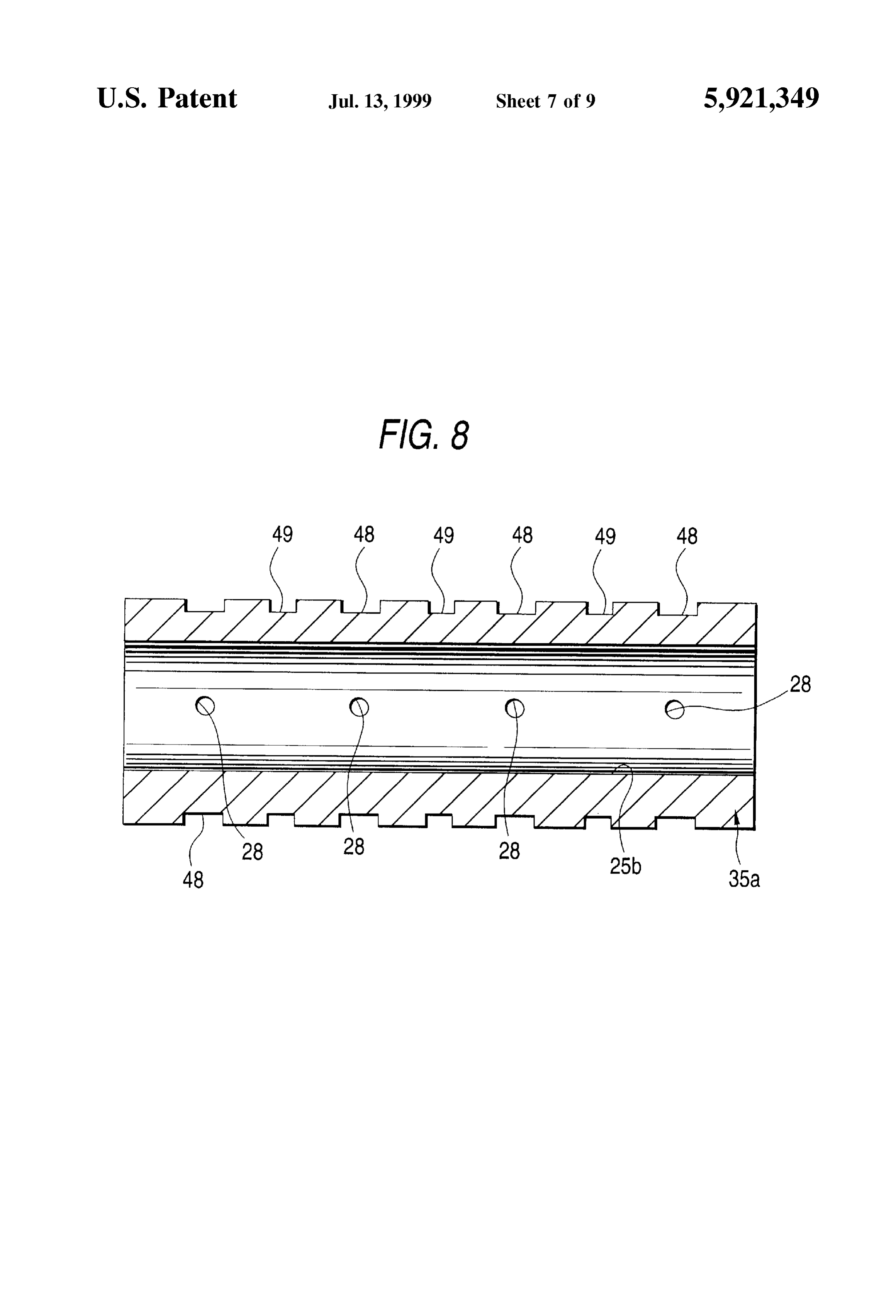
with the inner-pipe-Side Small holes and a plurality of Seal FIG. 8 is a sectional view of an inner pipe in FIG. 7;
Page 13
S 6
FIG. 9 is a sectional view showing an example of the small hole 28 and one outer-pipe-side small hole 30 are conventional Structure; and formed in one (left in FIG. 1) outer pipe 19a and two FIG. 10 is an enlarged view of the portion D in FIG. 9. inner-pipe-side Small holes 28, 28 and two outer-pipe-side Small holes 30, 30 are formed in the other (right in FIG. 1)
DETAILED DESCRIPTION OF THE outer pipe 19b. Further, the inner-pipe-side small holes 28, PREFERRED EMBODIMENTS 28, the first recessed grooves 29, 29, the outer-pipe-side small holes 30, 30 and the branch passages 7a and 7b are
FIGS. 1 to 3 show a first embodiment of the present located axially as follows. When the seal rings 24, 24 are invention. The feature of this oil air lubricating apparatus compressed between the Supply plug 22 and the flange according to the invention is in the Structure of an oil air portion 27 provided in the inner pipe 18 in the condition in distributor 17 provided in the inside of a support hole 8a which the outer pipes 19a and 19b, the seal rings 24, 24 and provided in a housing 16. The structure of a portion in which the spacer 20 are fitted onto the inner pipe 18, the inner a plurality of branch passages 7a and 7b are provided for pipe-side small holes 28, 28 are matched with the first Supplying lubricating oil to a portion Supporting a rotation recessed grooves 29, 29 So that not only the inner-pipe-side shaft 2 (see FIG.9) rotatably relative to the housing 16 is the 15 small holes 28, 28 are communicated with the outer-pipe Same as the preliminarily described conventional Structure. side Small holes 30, 30 respectively but also the outer-pipe Although this embodiment shows the case where the number side small holes 30, 30 are communicated, respectively, with of branch passages for Supplying lubricating oil is two for the branch passages 7a and 7b provided in the housing 16. the Sake of Simplification of description, the number of Incidentally, in this embodiment, Second recessed grooves branch passages may be not Smaller than three. 34, 34 are formed in the inner circumferential Surface of the The oil air lubricating apparatus according to the present Support hole 8a So as to be located in positions axially invention comprises: a Support hole 8a provided in the matched with the branch passages 7a and 7b respectively. inside of the housing 16; a plurality of branch passages 7a The circumferential position restriction on fixture of the and 7b each having one end (upper end in FIG. 1) opened to outer pipes 19a and 19b to the support hole 8a is made the inner circumferential Surface of the Support hole 8a and 25 unnecessary because of the Second recessed grooves 34, 34. the other end (lower end in FIG. 1) opened to a portion to Incidentally, the Second recessed grooves 34, 34 may be be lubricated, Such as a not-shown roller bearing, or the like; formed in axially intermediate portions of the outer circum and an oil air distributor 17 provided in the inside of the ferential surfaces of the outer pipes 19a and 19b, Support hole 8a. The one-end-side openings of the branch respectively, instead of the inner circumferential Surface of passages 7a and 7b are opened in axially Separate positions the Support hole 8a. Further, the spacer 20 has a function for respectively on the inner circumferential Surface of the limiting the interval between the outer pipes 19a and 19b. support hole 8a. Further, the Supply plug 22 has a connection portion 21 The oil air distributor 17 is constituted by: an inner pipe which can be connected to the opening portion of the Support 18; a plurality of outer pipes 19a and 19b (two in FIG. 1) hole 8a through thread-engagement, and a Second oil-Supply which can be fitted onto the inner pipe 18 with fine gaps 35 hole 31 for making the axially opposite end Surfaces com therebetween; a cylindrical Spacer 20, a Supply plug 22 municate with each other. In this example, the outer circum having a connection portion 21 which can be connected to ferential Surface of the connection portion 21 is provided as an opening end portion of the Support hole 8a through a male Screw portion So that the male Screw portion can be thread-engagement; and a plurality of Seal rings 24, 24 thread-engaged with a female Screw portion formed in the which are annular Sealing members respectively. The inner 40 opening end portion of the Support hole 8a. Further, a Second pipe 18 has a bottomed-cylinder-shaped pipe portion 26 and flange portion 32 protruded radially outward is formed on a flange portion 27. The pipe portion 26 is opened at this one the outer circumferential Surface of the Supply plug. 22. end side (left in FIG. 1) and provided with a first oil-supply The constituent members of the oil air distributor 17 hole 25 formed in its inside. The flange portion 27 is configured as described above are used in combination as provided on the outer circumferential Surface of the other 45 shown in FIG.1. That is, the outer pipes 19a and 19b and the end portion (right end portion in FIG. 1) of the pipe portion Spacer 20 are fitted, through the Seal ringS 24, 24, onto the 26. The inner pipe 18 can be inserted into the inside of the outer circumferential Surface of the pipe portion 26 consti Support hole 8a. Further, a plurality of inner-pipe-Side Small tuting the inner pipe 18. The outer pipes 19a and 19b, the holes 28, 28 are formed in an intermediate portion of the spacer 20 and the seal rings 24, 24 are axially held between pipe portion 26 So as to be disposed in axially Separate 50 a surface (left surface in FIG. 1) of the flange portion 27 positions, in circumferentially even-level positions and in provided in the inner pipe 18 and the connection portion 21 radially opposite positions, So that the inner and outer Side end Surface of the Supply plug. 22. Incidentally, the outer circumferential Surfaces of the pipe portion 26 are commu diameter of each of the Seal rings 24, 24 is Selected to be nicated with each other through those small holes 28, 28. slightly smaller than the diameter of the Support hole 8a in Further, each of the outer pipes 19a and 19b can be fitted 55 the condition in which the seal rings 24, 24 are fitted onto the onto the pipe portion 26 of the inner pipe 18 with a fine gap pipe portion 26 of the inner pipe 18 so that the oil air and can be inserted into the Support hole 8a. First recessed distributor 17 with the seal rings 24, 24 can be inserted in the grooves 29, 29 are provided in axially intermediate portions inside of the Support hole 8a easily. over the whole inner circumferential Surfaces of the outer The thus assembled oil air distributor 17 is inserted in the pipes 19a and 19b respectively. Further, an outer-pipe-side 60 inside of the Support hole 8a. Then, the male screw portion small hole 30 is formed in a part of each of the outer pipes provided in the connection portion 21 of the Supply plug 22 19a and 19b so that the bottom Surfaces of the first recessed is thread-engaged with the female Screw portion provided in grooves 29, 29 are communicated with the outer circumfer the opening end portion of the Support hole 8a and tightened. ential surfaces of the outer pipes 19a and 19b respectively. The Seal rings 24, 24 are compressed in this condition So that Incidentally, in the embodiment shown in the drawings, the 65 not only the inner circumferential edges of the Seal rings 24, inner-pipe-Side Small holes 28, 28 and the Outer-pipe-side 24 are elastically pressed against the outer circumferential small holes 30, 30 are provided so that one inner-pipe-side surface of the pipe portion 26 all over the whole circumfer
Page 14
ence but also the Outer circumferential edges of the Seal rings Next, FIG. 4 shows a second embodiment of the inven 24, 24 are elastically pressed against the inner circumferen tion. An oil air lubricating apparatus of the embodiment, tial Surface of the Support hole 8a all over the whole unlike that of the first embodiment, is not provided with the circumference. Further, in this condition, the first oil-Supply Supply plug 22 or the flange portion 27 (see FIG. 1). Instead, hole 25 and the second oil-supply hole 31 are communicated an oil air distributor 17a forming a part of the oil air with each other, the inner-pipe-side small holes 28, 28 and lubricating apparatus comprises a Supply plug portion 37 the outer-pipe-side small holes 30, 30 are communicated integral with an inner pipe 18a in one end thereof (left end with each other, and the outer-pipe-side small holes 30, 30 part of FIG. 4), a male screw portion 38 formed on the outer and the branch passages 7a and 7b provided in the housing peripheral Surface of an opposite end of the inner pipe 18a 16 are communicated with each other. (right end part of FIG. 4), and a nut 39 that can be screwed Further, in the case where the oil air distributor 17 is into the male screw portion 38. The Supply plug portion 37 inserted in the inside of the support hole 8a in the afore and a pipe portion 26 disposed from an intermediate part of mentioned manner, the inner-pipe-Side Small holes 28, 28 the inner pipe 18a to an opposite half part are made provided in the inner pipe 18 are limited So as to be opened contiguous by a step portion 40. The Supply plug portion 37 Substantially horizontally (at least to a portion except the 15 is formed in a part of the Outer peripheral Surface with a third neighborhood of the lower end portion in the circumferential flange portion 41 projected diametrically outward and the direction) in the inner circumferential Surface of the first third flange portion 41 is formed with a plurality of through oil-Supply hole 25. Incidentally, in this example, a packing holes 42, 42 axially penetrating the third flange portion 41. 33 is interposed between the second flange portion 32 of the One side of the third flange portion 41 (left side face of FIG. Supply plug 22 and the opening circumferential edge portion 4) can be abutted via a packing 33 against a portion existing of the Support hole 8a so that oil tightness between the in an opening fringe part of a Support hole 8a made in a Supply plug 22 and the Support hole 8a is held. housing 16 on the outer face of the housing 16 with the inner In the oil air lubricating apparatus configured as described pipe 18a inserted into the Support hole 8a. In this state, the above according to the present invention, constituent mem through holes 42, 42 made in the third flange portion 41 can bers of the oil air distributor 17 can be handled collectively 25 be aligned with bolt holes 43, 43 made in a portion posi in the condition in which the constituent members are tioned in the opening fringe part of the Support hole 8a in a assembled into one body even in the case where the number part of the outer face of the housing 16. With the through of portions for Supplying lubricating oil is two or more. holes 42, 42 aligned with the bolt holes 43, 43, bolts 44, 44 Further, because the shape perse of each constituent mem inserted into the through holes 42, 42 are screwed into the ber is relatively simple, the Structure is simplified and the bolt holes 43, 43, whereby the Supply plug portion 37 is assembling work is facilitated So that the cost of the appa joined to the housing 16. Therefore, in the embodiment, the ratus is reduced. That is, at the time of the assembling work, Supply plug portion 37 is not formed on the outer peripheral the oil Supply Source led to the Second oil-supply hole 31 surface with the male screw portion (see FIG. 1) provided to provided in the Supply plug 22 can be communicated with enable the Supply plug 22 in the first embodiment to be portions to be lubricated through the branch passages 7a and 35 joined to the housing 16.
7b provided in the housing 16 simply by an operation in The members making up the oil air distributor 17a are which the Supply plug 22 is fixed thread-engaged with the combined in a state in which the inner pipe 18a is not opening portion of the Support hole 8a to compress the inserted into the support hole 8a, as shown in FIG. 4. That sealing members 24, 24 after the oil air distributor 17 is, with the inner pipe 18a not inserted into the Support hole including the outer pipes 19a and 19b, sealing members 24, 40 8a, two outer pipes 19a and 19b and one spacer 20 are fitted 24 and spacer 20 fitted onto the inner pipe 18 is inserted in onto the outer peripheral Surface of the pipe portion 26 the inside of the support hole 8a provided in the housing 16. forming the inner pipe 18a via a plurality of Seal rings 24, Accordingly, no exclusive-use jig and complex labor are 24, and the nut 39 is screwed into the male screw portion 38 required for the assembling work to Secure the aforemen provided on the outer peripheral Surface of the opposite end tioned communication State. Although this embodiment has 45 of the pipe portion, whereby the outer pipes 19a and 19b, the shown the case where the number of portions to be Supplied Spacer 20, and the Seal rings 24, 24 are Sandwiched axially with lubricating oil is two and the number of branch pas between one side of the nut 39 (left side face of FIG. 4) and Sages 7a and 7b is two, the present invention can be applied the Step portion 40, one side of the Supply plug par 37 (right to the case where the number of portions to be supplied with side face of FIG. 4), and the seal rings 24 and 24 are lubricating oil is not Smaller than three if a separate outer 50 compressed axially. In this State, the Outer diameter of each pipe, a separate Spacer, etc. are used in combination. Also in Seal ring 24, 24 is made a little larger than the inner diameter this case, easy handling is obtained, So that the production of the Support hole 8a.
cost for the apparatus is reduced. The oil air distributor 17a with the members thus com Further, according to the illustrated oil air lubricating bined is inserted into the Support hole 8a, the third flange apparatus, a plurality of inner-pipe-Side Small holes 28, 28 55 portion 41 is struck against the outer face of the housing 16 are opened Substantially horizontally in Vertically even-level via the packing 33, and the through holes 42, 42 made in the positions in the inner circumferential Surface of the first third flange portion 41 and the bolt holes 43, 43 made in the oil-Supply hole 25. Accordingly, lubricating oil can be fed housing 16 are aligned with each other. In this State, the into the inner-pipe-side Small holes 28, 28 uniformly even in opposite end face of the inner pipe 18a faces the deep end the case where the lubricating oil is reserved in the lower 60 face of the Support 8a with a gap between. In this State, the portion of the inside of the first oil-supply hole 25 by the bolts 44 and 44 inserted into the through holes 42 and 42 are influence of the gravity. Incidentally, in the illustrated Screwed into the bolt holes 43 and 43 and further are example, the female Screw portion 23 formed in the opening tightened for joining and fixing the Supply plug portion 37 portion of the first oil-supply hole 25 is used for thread to the housing 16. In this State, the Seal rings 24, 24 are engagement with the top end portion of a bolt used as a clue 65 compressed diametrically between the Outer peripheral Sur to go on when the oil air distributor 17 is drawn out of the face of the inner pipe 18a and the inner peripheral Surface of support hole 8a. the Support hole 8a and the inner and Outer fringes of the Seal
Page 15
ringS 24, 24 are elastically abutted against the outer periph end of the first oil supply hole 25a is closed. The inner pipe eral Surface of the pipe portion 26 and the inner peripheral 35 can be inserted into a support hole 8a made in a part of surface of the support hole 8a over all peripheries. A first oil a housing 16 and one end of the inner pipe 35 (left end of Supply hole 25 made in the pipe portion 26 and a Second oil FIG. 5) projects to the inside of a female screw portion 47 Supply hole 31a made in the Supply plug portion 37 com formed in the opening end of the Support hole 8a in a State municate with each other; the inner-pipe-Side Small holes 28, in which the inner pipe 35 is inserted into the Support hole 28 made in the pipe portion 26 and the Outer-pipe-Side Small 8a until an opposite end of the inner pipe 35 Strikes against holes 30, 30 made in the outer pipes 19a, 19b communicate the deep end of the support hole 8a. with each other; and the outer-pipe-side small holes 30, 30 A plurality of recessed grooves 48, 48 are formed at and branch passages 7a, 7b defined in the housing 16 axially different positions on the outer peripheral Surface of communicate with each other. the pipe portion 45 over all periphery and a plurality of Seal With the oil air lubricating apparatus of the embodiment grooves 49, 49 are formed at positions axially apart from the configured as described above, the oil air distributor 17a can recessed grooves 48, 48 over all periphery. A plurality of be handled reliably in one piece in a state before it is fitted small holes on the inner pipe side 28, 28 to allow the bottoms into the housing 16, thus handleability of the oil air dis 15 of the recessed grooves 48, 48 and the inner peripheral tributor 17a furthermore improves as compared with that in Surface of the pipe portion 45 to communicate with each the first embodiment and the fitting work of the oil air other are made So as to be spaced from each other in the axial lubricating apparatus can be furthermore facilitated accord direction of an intermediate part of the pipe portion 45 at the ingly. Further, in the Second embodiment, the Supply plug Same position in the circumferential direction and at dia portion 37 is joined to the housing 16 with the bolts 44, 44, metrically opposite positions.
thus the inner-pipe-side small holes 28, 28 made in the inner The inner pipe 35 thus formed, a nut member 51, and a pipe 18a can be reliably opened almost horizontally at the supply plug 22 make up the oil air distributor 17b. The nut Same position in the height direction of the inner peripheral member 51 is formed on the outer peripheral Surface with a surface of the first oil supply hole 25. That is, in the first male screw portion 52 that can be screwed into the female embodiment, the inner pipe 19a and the Supply plug 21 25 Screw portion 47 disposed at the end of the opening of the (FIG. 1) having a portion that can be joined to the housing support hole 8a and contains a third oil supply hole 53 16 are separate and there is the possibility that the opening axially penetrating the nut member 51. The nut member 51 positions and opening directions of the inner-pipe-Side Small is screwed into the female screw portion 47, whereby it is holes 28, 28 may be unable to be reliably made predeter joined to the housing 16. The axial length of the nut member mined ones. In contrast, in the Second embodiment, the inner 51 is regulated to the length to allow a male Screw portion pipe 18a and the Supply plug portion37 having a portion that of a connection portion 21 of the Supply plug 22 to be can be joined to the housing 16 are formed in one piece and Screwed into the opening end of the female Screw portion 47 to fix the inner pipe 18a to the inside of the support hole 8a, in a state in which the inner pipe 35 is inserted into the the inner pipe 18a is joined and fixed to the housing 16 by support hole 8a until an opposite end of the inner pipe 35 means of the bolts 44, 44 in a state in which the through 35 Strikes against the deep end of the Support hold 8a and the holes 42, 42 made in the third flange portion 41 of the supply nut member 51 is screwed hole into the deep end of the plug portion 37 and the bolt holes 43, 43 made in the housing female screw portion 47.
16 are aligned with each other. Therefore, if the positional In the embodiment, a small hole 54 axially penetrating the relationship between the through holes 42, 42 and the bottom plate portion 46 is made in the center of the bottom inner-pipe-Side Small holes 28, 28 is properly regulated, the 40 plate portion 46. The housing 16 contains a Second branch inner-pipe-side Small holes 28, 28 can be reliably opened passage 55 with an upstream end opened on the deep end almost horizontally at the same position in the height face of the Support hole 8a and a downstream end opened in direction of the inner peripheral Surface of the first oil Supply a portion to be lubricated. That is, the Second branch passage hole 25. Therefore, in the embodiment, even if the lubricat 55 is made up of a concave hole 56 opening the upstream ing oil Supply amount is minute and the lubricating oil 45 end in the center of the deep end face of the support hold 8a accumulates in the bottom because of the effect of gravity in and a through hole 57 opening the upstream end on the inner the first oil supply hole 25, the lubricating oil can be stably peripheral surface of the concave hole 56 and the down supplied to the branch passages 7a and 7b defined in the stream end in the portion to be lubricated. With the inner housing 16. pipe 35 inserted into the Support hole 8a, the small hole 54 Other components similar to those previously described in 50 made in the bottom plate portion 46 of the inner pipe 35 and the first embodiment are denoted by the same reference the Second branch passage 55 are made to communicate with numerals and will not be discussed again. each other.
Next, FIGS. 5 and 6 show a third embodiment of the The members making up the oil air distributor 17b formed invention. An oil air lubricating apparatus of the as described above are inserted into the Support hole 8a with embodiment, unlike those of the above-mentioned 55 the members assembled as shown in FIG. 5 or are assembled embodiments, is not provided with the outer pipes 19a, 19b as shown in FIG. 5 with the members inserted into the (see FIGS. 1 to 4). Instead, an inner pipe 35 forming a part Support hole 8a. That is, annular Seal ringS 24, 24 are fitted of an oil air distributor 17b is made up of a pipe portion 45 into the seal grooves 49, 49 formed on the outer peripheral containing a first oil Supply hole 25a opened to one axial end surface of the inner pipe 35. In this state, the outer diameter (left end of FIG. 5) and a bottom plate portion 46 for closing 60 of each Seal ring 24, 24 becomes a little larger than the inner an opening at an opposite end of the first oil Supply hole 25a diameter of the support hole 8a. With the bottom plate (right end of FIG. 5); it is shaped like a closed-end cylinder portion 46 positioned on the deep end Side of the Support as a whole. To form the inner pipe 35 as described above, in hole 8a, the inner pipe 35 is inserted into the Support hold the embodiment, a disk-like member is joined and fixed to 8a. Next, the nut member 51 is screwed into the female a cylinder-like member formed in the inside with the first oil 65 screw portion 47 and is further tightened until one side of the Supply hole 25a axially penetrating the cylinder-like mem nut member 51 (right side face of FIG. 5) strikes against one ber by welding in a State in which the opening at the opposite end face of the inner pipe 35, whereby the inner pipe 35 is
Page 16
Sandwiched between the one side of the nut member 51 and grooves 48, 48 and a plurality of seal grooves 49, 49 over all the deep end face of the support hold 8a and is fixed to the periphery. A plurality of inner-pipe-side small holes 28, 28 housing 16 together with the nut member 51. Last, the male to allow the bottoms of the recessed grooves 48, 48 and the Screw portion of the Supply plug 22 is Screwed into the inner peripheral Surface of the inner pipe portion 35a to opening end of the female Screw portion 47 for joining and communicate with each other are made So as to be spaced fixing the Supply plug 22 to the housing 16. from each other in the axial direction of an intermediate part In this State, the Seal ringS 24, 24 are compressed dia of the inner pipe 35 at the same position in the circumfer metrically between the bottoms of the seal grooves 49, 49 ential direction and at diametrically opposite positions. The and the inner peripheral Surface of the Support hole 8a and in a housing35a inner pipe can be inserted into a Support hole 8a made 16a and both end faces of the inner pipe 35a can the inner and Outer fringes of the Seal rings 24, 24 are be struck against one end face of a Supply plug. 22a and the elastically abutted against the bottoms of the Seal grooves deep end face of the Support hole 8a. In the embodiment, 49, 49 and the inner peripheral surface of the support hole unlike the third embodiment, the second branch passage 55 8a over all peripheries. In this State, a first oil Supply hole (FIG. 5) is not defined in the housing 16a. The female screw 25a made in the inner pipe 35 and a second oil supply hole portion 47 as in the first or third embodiment (see FIG. 1, 31 made in the Supply plug 22 communicate with each other; 15 FIG. 5) is not formed in an opening end of the support hole the inner-pipe-Side Small holes 28, 28 made in the inner pipe 8a; instead, a seal groove 58 is formed over all periphery. 35 and branch passages 7a, 7b, and 7c defined in the housing The Supply plug. 22a can be joined to the opening end of the 16 communicate with each other; and the Small hole 54 Support hole 8a. That is, the Supply plug. 22a has the outer made in the bottom plate portion 46 and the second branch peripheral surface of one end (right end of FIG. 7) as a passage 55 defined in the housing 16 communicate with Simple cylindrical face and is formed with a Second flange each other. portion 32a on the outer peripheral Surface of an interme Since the oil air lubricating apparatus of the embodiment diate part. The one end of the Supply plug. 22a is pressed into the opening end of the Support hole 8a, whereby the Supply configured as described above has a Structure wherein the plug. 22a can be joined and fixed to the housing 16a. outer pipes 19a and 19b are excluded from the oil air 25 Particularly in the embodiment, the housing 16a forming lubricating apparatus of the first or Second embodiment, the a part of the oil air lubricating apparatus contains a plurality number of parts of the oil air distributor 17b can be lessened. of branch passages 59, 59 each having an upstream end Further, unlike the inner pipes in the first and Second opened on the inner peripheral Surface of the Support hole 8a embodiments, the inner pipe 35 forming a part of the oil air and a downstream end opened on the outer face of the distributor 17b need not be formed with the flange portion 27 housing 16a. Upstream ends of oil air supply pipings 60, 60 (FIG. 1), the male screw portion 38 (FIG. 4), etc., and thus are connected to opposite end openings of the branch can be manufactured at low costs simply by applying easy passages 59, 59 opened on the outer face of the housing 16a working to a material Such as a carbon Steel pipe for preSSure by pipe joints 61, 61. Downstream ends of the oil air supply piping. Further, fitting work required to make the oil Supply pipings 60, 60 (not shown) are connected to another housing Source leading to the Second oil Supply hole 31 communicate 35 (not shown) with the portions to be lubricated to which the branch as a Support provided with a portion to be lubricated, such part of a rolling bearing, whereby the oil air passages 7a, 7b, 7c and 55 defined in the housing 16 lead can Supply pipingS 60, 60 are made to communicate with the be furthermore facilitated. Therefore, in the embodiment, the whole costs of the oil air lubricating apparatus can be portion supply to be lubricated. The Structure of joining the oil air pipings 60, 60 to the ends of the branch passages 59, reduced.
40 59 defined in the housing 16a as described above is gener
Further, in the embodiment, the small hole 54 axially ally known and therefore a detailed description of the penetrating the bottom plate portion 46 forming a part of the connection parts of the oil air Supply pipingS 60, 60 is inner pipe 35 is made in the bottom plate portion 46 and the omitted.
Second branch passage 55 made to communicate with the To assemble the oil air lubricating apparatus configured as small hole 54 is defined in the housing 16, so that a large 45 described above, the inner pipe 35a is inserted into the number of portions to be lubricated can be provided. In the support hole 8a with seal rings 24, 24 fitted into the seal embodiment, the Small hole 54 is made in the center of the grooves 49, 49 formed in the outer peripheral surface of the bottom plate portion 46. Thus, if the inner-pipe-side small inner pipe 35a. In this State, a connection portion 21a of the holes 28, 28 made in the pipe portion 45 are opened almost Supply plug. 22a is pressed into the opening end of the horizontally at the Same position in the height direction on 50 Support hole 8a, whereby the Supply plug. 22a is joined and the inner peripheral Surface of the first oil supply hole 25a fixed to the housing 16a and the inner pipe 35a is sand with the inner pipe 35 inserted into the Support hole 8a, the wiched between the one end face of the Supply plug. 22a and small hole 54 made in the bottom plate portion 46 and the the deep end face of the support hole 8a for fixing the inner inner-pipe-side small holes 28, 28 become the same in pipe 35a to the housing 16a. In this State, annular Seal ring height position and equal amounts of lubricating oil can be 55 24 is fitted into the seal groove 58 formed in the opening end supplied to the holes 54 and 28. of the Support hole 8a, whereby the seal ring 24 is com Other components similar to those previously described in pressed elastically between the bottom of the seal groove 58 the first embodiment are denoted by the same reference and the outer peripheral Surface of the Supply plug. 22a for numerals and will not be discussed again. holding oil-Sealing relation between the Support hole 8a and Next, FIGS. 7 and 8 show a fourth embodiment of the 60 the supply plug. 22a. In this state, the first oil supply hole 25b invention. In an oil air lubricating apparatus of the made in the inner pipe 35a and the second oil supply hole 31 embodiment, an inner pipe 35a forming a part of an oil air made in the Supply plug. 22a communicate with each other distributor 17c is shaped almost like a cylinder as a whole and the inner-pipe-side small holes 28, 28 made in the inner and contains a first oil Supply hole 25b axially penetrating pipe 35a and the branch passages 59, 59 defined in the the inner pipe 35a. Like the inner pipe 35 in the third 65 housing 16a communicate with each other. embodiment (FIGS. 5 and 6), the inner pipe 36a is formed According to the oil air lubricating apparatus of the on the outer peripheral Surface with a plurality of recessed embodiment configured as described above, a So-called
Page 17
installation-type oil air distributor with the housing 16a into of Said annular Sealing members are elastically abutted which the oil air distributor 17c is fitted separate from a against the inner circumferential Surface of Said Support housing (not shown) provided with a portion to be hole and inner fringes of Said annular Sealing members lubricated, Such as a Support part of a rolling bearing, can be are elastically abutted against an outer circumferential provided. Therefore, the housing 16a into which the oil air Surface of Said inner pipe, So that Said first oil-Supply distributor 17c is fitted can be miniaturized, the flexibility of hole and Said Second oil-Supply hole are communicated the installation position of the housing 16a can be improved, with each other, Said inner-pipe-Side Small holes and and effective use of the space in which the whole oil air Said outer-pipe-Side Small holes are communicated with lubricating apparatus is built can be made. For example, the each other, respectively, and Said outer-pipe Side Small housing 16a into which the oil air distributor 17c is fitted is holes and Said branch passages provided in Said hous fixed to the top, etc., of another housing (not shown) ing are communicated with each other, respectively. provided with a portion to be lubricated. 2. The oil air lubricating apparatus according to claim 1, wherein Said holding means comprises a Supply plug Sepa
With the oil air lubricating apparatus of the embodiment rate from Said inner pipe.
configured and functioning as described above, the shape of 3. The oil air lubricating apparatus according to claim 2, the inner pipe 35a forming a part of the oil air distributor 17c 15 further comprising a flange portion disposed on an outer can be simplified, the manufacturing costs of the parts can be reduced, and the whole costs of the oil air lubricating circumferential portion of Said
Surface of an opposite end Side of Said pipe inner pipe and with Said Supply plug con apparatus can be decreased. nected to Said opening end portion of Said Support hole, Said Because the present invention is configured So as to flange portion of Said inner pipe and Said outer pipes are operate as described above, it is possible to provide an oil air Sandwiched between one end Surface of Said Supply plug and lubricating apparatus in which not only cost is reduced by a deep end of Said Support hole via a plurality of Said Sealing Simplification of machining of parts and reduction of labor members and Said Sealing members are compressed axially, for the assembling work but also proper quantities of lubri thereby Swelling diametrically.
cating oil can be distributed. 25 4. The oil air lubricating apparatus according to claim 1, What is claimed is: wherein Said holding means comprises a Supply plug portion 1. An oil air lubricating apparatus comprising: integral with Said inner pipe.
(1) a housing provided with a Support hole; 5. The oil air lubricating apparatus according to claim 4, (2) a plurality of branch passages formed in an inside of wherein said oil air distributor further includes a screw part Said housing, Said branch passages having respective formed on an outer peripheral Surface of an opposite end one ends opened in axially Separate positions in an Side of Said inner pipe, and a nut Screwed into Said Screw inner circumferential Surface of Said Support hole and part, and wherein Said inner pipe is inserted into Said Support respective other ends communicated with portions to be hole with Said outer pipes Sandwiched between one side of lubricated respectively; and Said Supply plug portion and one side of Said nut Screwed (3) an oil air distributor provided in an inside of said 35 into6. Said The
Screw part via a plurality of Said Seal members.
oil air lubricating apparatus according to claim 1,
Support hole;
Said oil air distributor including: wherein an upstream end of oil air Supply piping is con (3.a) an inner pipe having a pipe portion provided with a nected passages to an opening of Said other end of each of Said branch on an outer Surface of Said housing, whereby a first oil-Supply hole formed in an inside of Said pipe downstream end of each of Said branch passage is made to portion, Said pipe portion being opened in one end Side 40 lead to the portions to be lubricated. thereof, said inner pipe being inserted into the inside of 7. The oil air lubricating apparatus according to claim 1, Said Support hole; wherein said oil air distributor further includes a bottom (3.b) a plurality of inner-pipe-side Small holes provided in plate disposed on an opposite end Side of Said pipe portion an intermediate portion of Said pipe portion and formed in axially Separate positions respectively So as to com 45 of made
Said inner pipe, Said bottom plate having a Small hole
So as to axially penetrate Said bottom plate, wherein municate inner and outer circumferential Surfaces of Said housing comprises a Second branch passage being Said pipe portion with each other; defined therein and having an upstream end opened on a (3.c) a plurality of cylindrical outer pipes fitted onto said deep end face of Said Support hole and a downstream end pipe portion and inserted into the inside of Said Support 50 opened in a portion to be lubricated, and wherein Said Small hole; hole of Said bottom plate and Said Second branch passage are (3d) outer-pipe-side Small holes for communicating outer made to communicate with each other with Said inner pipe circumferential Surfaces of Said outer pipes with bottom inserted into Said Support hole.
Surfaces of recessed grooves formed in axially inter 8. An oil air lubricating apparatus comprising: mediate portions of inner circumferential Surfaces of 55 (1) a housing provided with a Support hole; Said outer pipes respectively; (2) a plurality of branch passages formed in an inside of (3e) a plurality of annular sealing members fitted onto part Said housing, said branch passages having respective of Said pipe portion and located in positions axially one ends opened in axially Separate positions in an Separated from Said outer pipes respectively, inner circumferential Surface of Said Support hole and (3f) means for holding (3a) to (3e) members in the inside 60 respective other ends communicated with portions to be of Said Support hole, Said holding means having a lubricated respectively; and connection portion which is connectable to an opening (3) an oil air distributor provided in an inside of said end portion of Said Support hole and a Second oil Support hole;
Supply hole which makes axially opposite end Surfaces Said oil air distributor including:
with each other; and 65 (3.a) an inner pipe having a pipe portion provided with a wherein, when said holding means is connected to the first oil-Support hole formed in an inside of Said pipe opening end portion of Said Support hole, outer fringes portion, Said pipe portion being opened in one end Side
Page 18
thereof, said inner pipe being inserted into the inside of of Said inner pipe and having bottom Surfaces made to Said Support hole; communicate with Said inner-pipe-Side Small holes and (3.b) a plurality of inner-pipe-side Small holes provided in a plurality of Seal grooves being formed at positions an intermediate portion of Said pipe portion and formed axially apart from Said recessed grooves on the outer in axially separate positions respectively So as to com- 5 peripheral Surface of Said inner pipe, wherein Said municate inner and outer circumferential Surfaces of plurality of annular Sealing members are fitted into Said Said pipe portion with each other; Seal grooves, respectively, and Said inner pipe is (3.c) a plurality of annular sealing members fitted onto part inserted into Said Support hole; and of Said pipe portion and located in positions axially wherein, with said holding means connected to said Separated from Said other pipes respectively; opening end portion of Said Support hole, Said Sealing (3d) means for holding (3a) to (3.c) members in the inside members are compressed diametrically between Said of Said Support hole, Said holding means having a bottom Surfaces of Said Seal grooves and the inner connection portion which is connectable to an opening circumferential Surface of Said Support hole, and Said end portion of Said Support hole and a Second oil- 15 inner-pipe-side Small holes and Said branch passages Supply hole which makes axially opposite end Surfaces defined in Said housing are made to communicate with with each other; and each other, respectively.
a plurality of recessed grooves being formed at axially different positions on the outer circumferential Surface k . . . .
Provenance
- Collection
- Cited prior art
- Original PDF
- patentimages.storage.googleapis.com →
- Filed
- 1998-09-29
- Pages
- 18
- Method
- pdftotext (the PDF's own text layer) + pdftoppm 300dpi page scans
- Source
- Google Patents bibliographic record
- Granted
- 1999-07-13
- Inventors
- Yukio Sato; Fumio Toyama; Yasushi Amano; NSK Ltd
- Transcribed from
- patentimages.storage.googleapis.com →