patent · US3361183
Liquid fuel burner
2 January 1968
Page 1
Drawing sheet — no readable text.
Page 2
Drawing sheet — no readable text.
Page 3
United States Patent Office 3,361,183 Patented Jan. 2, 1968
3,361,183 instability. Consequently, unless the velocities, which the LIQUID FUEL BURNER impellers imparted to the swirling fuel and air, were Robert Reichheim, Wallingford, Conn., assignor to Com carefully regulated or controlled, the flame would tend bastion Efficiency Corporation, Darien, Conn. to be blown away from the tip of the burner and thus Filed July 28, 1965, Ser. No. 475,377 result in a burner flame-out, which unless quickly detect 9 Claims. (C. 158-5) ed could and did create serious hazardous conditions in the System in which such burner was used.
ABSTRACT OF THE DESCLOSURE
The incomplete combustion of liquid fuel also created a maintenance problem in that the formation and ac
This invention is directed to a liquid fuel burner com cumulation of residue resulting therefrom required fre prising a burner nozzle having an inlet end and a dis quient cleaning of the burner parts to maintain the burner charge end portion for providing an unimpeded flow at optimum operating efficiency. Consequently, the path therethrough for the fuel mixture. A means defining known oil burner constructions have never achieved the a gasifying chamber is operatively connected to the cleanliness or efficiency of operation comparable to that burner nozzle for effecting gasification of the liquid fuel 5 of gas burners.
introduced thereinto. The heat for effecting gasification Efficient combustion and maintenance of liquid fuel of the liquid fuel in the gasification chamber is effected burners become even more aggravated when such burners by providing a plurality of port openings spaced inwardly are supplied with a relatively low-grade of fuel oil. Also, and adjacent the discharge end portion of the burner the structure of the prior known liquid fuel burners have nozzle so as to effect recirculation of a portion of the 20 not been readily adapted for burning a gaseous fuel as products of combustion generated in or at the burner the structure of the known burners for liquid fuel has nozzle to the gasification chamber. Disposed in communi not been compatible for the burning of a gaseous fuel. cation between the gasifying chamber and the inlet to Consequently, in installations requiring the use of gas the burner nozzle is a mixing chamber having a restrictor as an alternate fuel, separate and distinct gas burner con formed therein. Accordingly, combustion air is intro 25 struction was required to accommodate the burning of duced into the mixing chamber whereby the flow of gas when used as an alternate fuel.
air through the restrictor induces a natural circulation it is therefore an object of this invention to provide to enhance the mixture of the combustion air with the a liquid fuel burner constructed and arranged so as to gasified fuel and which creates a zone of reduced pres affect complete gasification of the liquid fuel supplied sure adjacent the circulating ports thereby permitting 30 so that it can be more intimately mixed with the neces the same to function as a means for retaining the fame sary combustion air prior to the burning of the same so adjacent the discharge end of the burner nozzle. that the efficiency and completeness of combustion of was rescottomaru the liquid fuel is greatly enhanced.
Another object of this invention is to provide a burner
This invention relates in general to a burner construc construction in which a portion of the products of com tion, and more specifically to a burner construction ar bustion generated by the burner are recirculated so that ranged to gasify a liquid fuel prior to burning to pro the heat of the combustion gases is utilized to effect gasi vide for a more intimate and homogeneous mixture of fication of the liquid fuel supplied to the burner. fuel and combustion air; and thereby achieve a more 40 Another object of this invention is to provide a liquid complete and efficient combustion of the fuel. fuel burner constructed and arranged in a manner in Many efforts have been made to develop a highly which flame stability is greatly enhanced and in which noise is substantially minimized.
efficient liquid fuel burner. Various means have been employed in the past to effect an optimum mixture of Another object of this invention is to provide a burner liquid fuel with the necessary combustion air to attain construction in which the liquid fuel supplied thereto a good combustible mixture. Heretofore, either mechani 45 is gasified and intimately mixed with combustion air to cal and/or physical means have been utilized for atomiz form a homogeneous fuel mixture in a manner in which ing the liquid fuel into a liquid fuel spray or mist to prohibits the condensation of the gasified fuel. render the same more readily mixed or combined with Another object of this invention is to provide a burner necessary air to create the optimum combustible mix construction in which preheated combustion air is inti ture. However, even with the best known atomizing mately mixed with the gasified fuel to form an optimum means, the desired homogeneous fuel mixture for opti combustible fuel mixture that is totally consumed to ef mum combustion efficiency was not readily attainable. fect a complete and efficient combustion of the liquid fuel. This was because the finely divided atomized particles Another feature of this invention resides in the pro of fuel was still confined to their liquid state and conse vision of a liquid fuel burner in which the liquid fuel quently the air could only combine with surface portions is gasified prior to burning and which is relatively simple of liquid fuel particles or droplets. Consequently, only which in structure, that can be inexpensively fabricated, and is positive in operation.
the smaller of the atomized fuel particles could be totally consumed if enveloped in sufficient combustion air. The Another object of this invention is to provide a liquid relatively larger particles of atomized fuel could only fuel burner in which the liquid fuel supplied thereto is be partially consumed, since the surrounding air would 60 quickly gasified prior to the combustion thereof. be insufficient to support the complete combustion Another object of this invention is to provide in a thereof. liquid fuel burner means for retaining and stabilizing the To further enhance the intimate mixing of the flame adjacent the discharge end of the burner nozzle. atomized fuel particles with combustion air, means in Another object of this invention is to provide in a liquid the form of impellers have also been utilized in con circulationfuel burner an arrangement which creates a natural re junction with the atomizing means to impart a whirling burner to create of a portion of combustion gases through the (or swirling action to the atomized fuel and air. However, adjacent the tip end of the burner an while such impellers have been somewhat successful in area of thereat.
reduced pressure that functions to retain the flame effecting a more thorough mixing of the atomized fuel with the combustion air, they introduced into the art of 70 The foregoing objects, and other features and advan tages are attained in a burner construction comprising a combustion additional problems, such as noise and flame means defining a burner nozzle operatively associated
Page 4
with a gasifying chamber. Liquid fuel is supplied to the Another feature of this invention resides in the pro gasifying chamber. By subjecting the liquid fuel in the vision of a liquid burner in which liquid fuel is gasified gasifying chamber to heat, the liquid fuel therein is and then is intimately mixed with combustion air to form transformed into its gaseous state. a homogeneous combustible fuel mixture by passing the In accordance with this invention, the liquid fuel dur Same through a Venturi-like restrictor. ing burner operation is gasified by recirculating a portion Another feature of this invention resides in the pro of the combustion gases generated by the burner through vision of a liquid fuel burner in which the liquid fuel is the gasifying chamber. Thus, the heat of the combustion transformed into its substantial gaseous state prior to gases is utilized to transform the liquid fuel into its sub the combustion by the direct heat transfer between prod stantially gaseous state within the gasifying chamber. O ucts of combustion generated by the burner and the In one form of the invention, the gasifying chamber is liquid fuel.
remotely disposed with respect to the burner nozzle and vision Another feature of this invention resides in the pro is connected to the nozzle by Suitable conduit means, Suppliedof thereto a burner having means in which the liquid fuel is gasified in an atmosphere containing through which a portion of the combustion gases is insufficient air to support combustion and thereby mini drawn off and circulated therebetween. 5
In another form of the invention the gasfying chamber mizes any danger of any flashback.
is disposed in heat transfer relationship with the burner Other features and advantages will become more nozzle with suitable port openings interconnecting the tions andapparent readily when considered in view of the specifica drawings in which:
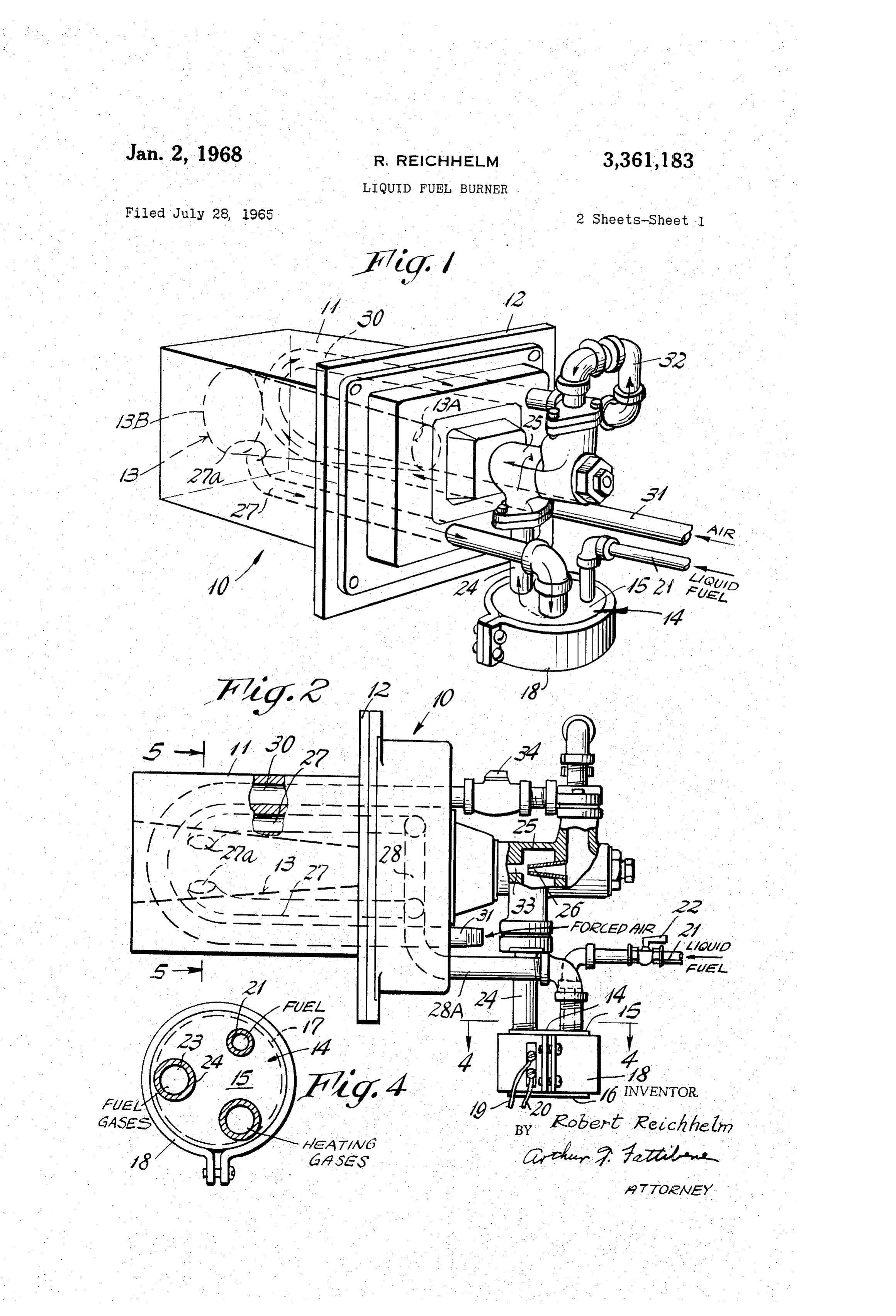
burner nozzle into direct communication with the gasify FIGURE 1 is a perspective view of a liquid fuel burner ing chamber to provide for the circulation of combustion 20 constructed in accordance with the instant invention. gases therebetween. FIGURE 2 is a side elevation view of the burner con In either form of the invention a means is provided for Struction of FIG. 1 having portions thereof shown in mixing combustion air with the gasified fuel and recir Section.
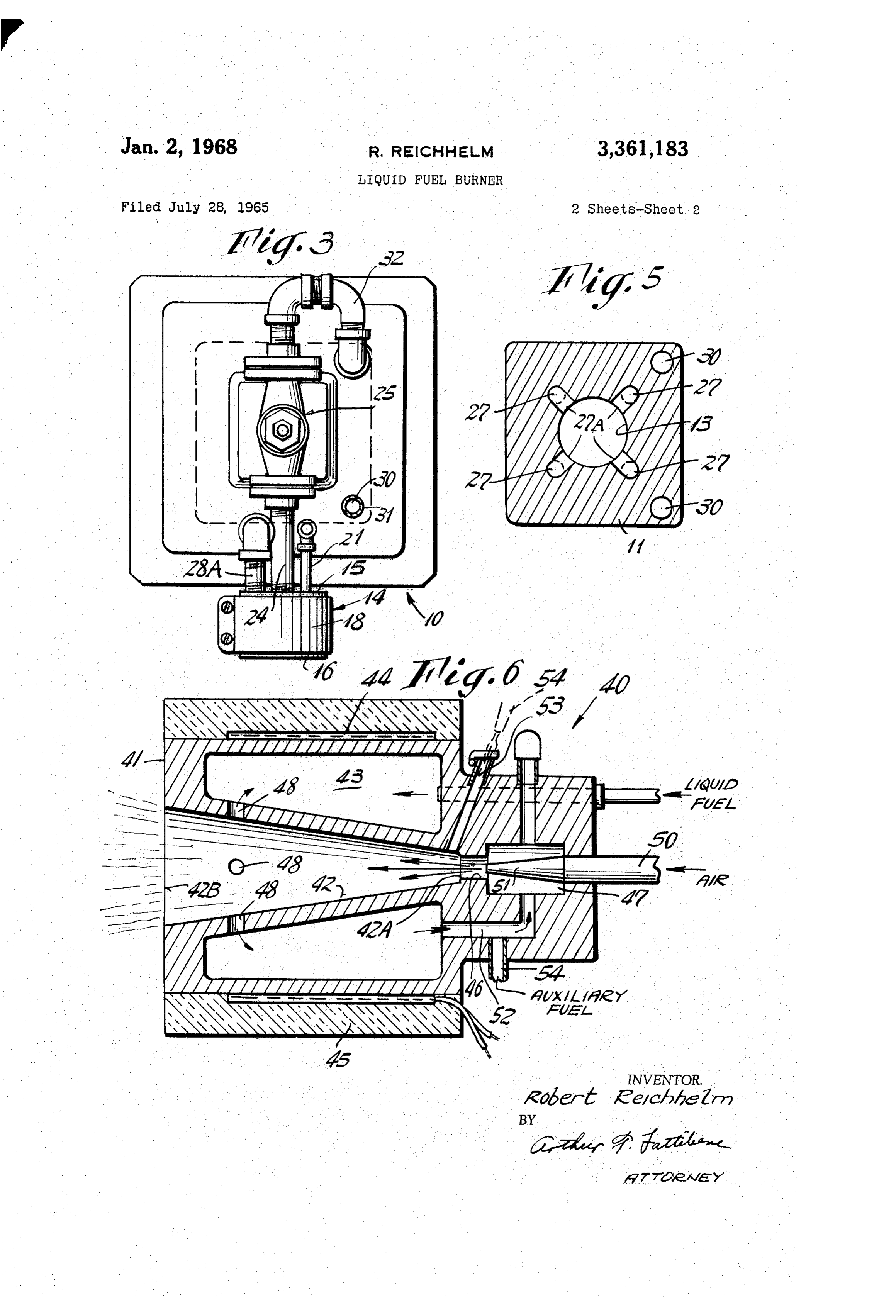
culated combustion gases mixed there with to form a 25 FIGURE 3 is a front end view of the burner construc homogeneous combustible fuel mixture. The mixing of tion of FIG. 1.
the combustion air with the gasified fuel mixture is at FIGURE 4 is a detailed plan view taken along line tained in a mixing chamber adjacent the inlet to the burner nozzle by passing the air through a Venturi-like 4-4 on FIG. 2.
FIGURE 5 is a detailed sectional view taken on line restrictor which is open in communication with the gasify 30 5-5 on FIG. 2.
ing chamber. Thus, a negative or reduced pressure Zone FIGURE 6 is a side sectional view taken through a created thereat causes the gasified fuel to flow from the burner block of a modified form of the invention. gasification chamber to the burner nozzle and to mix with Referring to the drawings, there is shown in FIGS. 1 the air flowing thereinto to define the combustible mixture through 5 an embodiment of a liquid fuel burner 10 con which is delivered to the burner nozzle. If desired, the Structed in accordance with the instant invention. The combustion air may be preheated by first passing the liquid burner 10 of FIGS. 1 to 5 comprises a burner block combustion air through an air heater, e.g. an air heater 11 having connected thereto a burner front plate 12 by means disposed in a heat exchange relationship to the which the burner 10 can be readily installed in a burner burner nozzle. Because the recirculating means of the combustion gases are connected into direct communica 40 opening of a furnace wall or burner box (not shown). tion with the gasifying chamber, the differential in pres The burner block 11 may be formed of any suitable high temperature, heat resistant, material, e.g. a ceramic or sure resulting from the flow of air through the restrictor other suitable fire resistant refractory material, and the induces a natural recirculation of a portion of the com like. Integrally formed within the block 1 is a bore bustion gases from the burner nozzle to the gasifying which defines a burner nozzle 13. In the illustrated form chamber associated therewith. Accordingly, a low pres of the invention, the bore defining burner nozzle 3 is sure area is created adjacent ports through which the shown as being substantially conical in shape and diverges combustion gases are drawn from the burner nozzle and recirculated to the gasification chamber. Preferably, these from the inlet 13A to the outlet end 13B thereof. Operatively connected with the burner nozzle 13 is a ports are disposed adjacent the discharge end of the gasifying chamber 14. In the illustrated embodiment of burner so that the area of reduced pressure created there FIGS. 1 through 3, the gasifying chamber 14 is defined at functions to retain and/or stabilize the flame at the burner tip during burner operation. Accordingly, as the block by a housing which is remotely connected to the burner load of the burner is increased, the greater becomes hold 11. Essentially, the gasifying chamber 14 comprises ing characteristics of the flame adjacent the discharge end a housing having top and bottom walls 15, 16 intercon of the burner nozzle. nected by a circumscribing side wall 17. An electric band if desired, a means may also be provided for supplying 55 heater 18 circumscribes the side wall 17 of the housing 14 an auxiliary fuel, as for example a gaseous fuel to the for reasons as will hereinafter appear with suitable con burner nozzle to render the burner readily compatible for ductors 19, 20 connecting the heater into a suitable elec tric circuit or source of electrical energy. A conduit 21 is burning either liquid fuel and/or gaseous fuel. connected into communication with the interior of the A feature of this invention resides in a burner con struction having in combination, a burner nozzle and co 60 gasifying chamber to supply liquid fuel thereto. To con operatively associated gasifying chamber with means for trol the flow of liquid fuel thereto, a valve or control 22 recirculating a portion of the combustion gases generated isgasifying interposed into the liquid supply conduit 21. The chamber 14 in turn is provided with an outlet in the burner nozzle to the gasifying chamber so that the 23, connected by a suitable conduit 24 to a fixture 25 heat of the combustion gases is utilized to gasify or trans which defines a chamber in which the gasified liquid fuel form the liquid fuel into a state to form with the com is mixed with combustion air supplied to the mixing cham bustion air a substantial homogeneous fuel mixture. ber 25 through a Venturi-like orifice or restrictor 26 Another feature of this invention resides in a burner having a construction in which the mixing of combustion whereby the air and gasified fuel are intimately mixed to define a homogeneous combustion mixture.
air with gasified liquid fuel creates a low pressure area or zone adjacent the tip end of the burner to function 70 plied In accordance with this invention, the liquid fuel sup as a means for retaining a stable flaming condition ad to the gasifying chamber 14 is gasified by imparting jacent the discharge end of the burner nozzle. heat thereto. This is attained by circulation in direct heat Another feature of this invention resides in a burner transfer with the liquid fuel of the heated product of construction which is rendered compatible for the burning combustion generated by the burner 10. In the form of either liquid and/or gaseous fuels. 75 the invention of FIGS. 1 to 5, the means for recirculation
Page 5
of a portion of the products of combustion to the gasifying On start-up, the valve 22, controlling the flow of liquid chamber 14 comprises one or more passageways or con fuel to the gasifying chamber, and valve 34 controlling duits 27 connecting the discharge end 13B of the burner nozzle 13 in communication with the gasifying chamber the in air flow through the air preheater 30 are proportioned accordance to a desired flame setting. To provide the 14. In the arrangement of FIGS. 1 to 5, four such pas sageways 27 are circumferentially spaced about the on start-up, the for heat necessary band initial gasification of the liquid fuel heater 18 surrounding the gasifying nozzle i3, each having an opening 27A adjacent the dis chamber 14 is energized. Accordingly, the band heater 18 charge end 13B of the burner nozzle. Preferably, the is maintained energized for a time sufficient to effect the ports 27A are circumferentially spaced about the tip end initial gasification of the liquid fuel within the gasifying of the nozzle. The outlet ends of the respective passages O chamber 14. If desired, there may be operatively con or conduits connect into a manifold 28 formed in the nected in the heater circuit a thermostatic switch (not burner block. The manifold 28 in turn connects into com shown) to insure maintenance of the proper temperature munication with the interior of the gasifying chamber 14 Within the gasifying chamber at all times during burner by means of a connecting conduit 28A. Accordingly, the operation arrangement is such that a portion of the products of 15 gization ofbytheautomatically effecting intermittent ener combustion generated by the ignition of the combustible within the gasifying chamber whenever band heater the temperature falls below the optimum fuel mixture within the burner nozzle 3 is recirculated to the gasifying chamber through passageways 27 as will temperature range hereinbefore set forth. After the initial gasification of the fuel oil has been be hereinafter more fully set forth. completed, the gasified fuel is directed to the mixing If desired, the combustion air to be mixed with the 20 chamber 25 by the flow of air passing through the Venturi gasified fuel may be preheated to avoid condensing of or orifice 26. Accordingly, the air and gasified fuel are the gasified fuel during mixing. As shown, means for intimately mixed into a homogenous fuel mixture which heating the combustion air comprises an air preheater is then supplied to the inlet of the burner nozzle. A suit disposed into heat transfer relationship with respect to able igniter means (not shown) effect ignition of the fuel the burner nozzle. In the illustrated form of the inven 25 Within the burner nozzle.
tion of FIGS. 1 to 5, the air preheater comprises a pas Once the operation of the burner has thus been com sageway 30 which is integrally formed in the burner block menced and the fuel ignited, the operation of the band in heat transfer relationship to the burner nozzle i3 heater 18 is discontinued except for possible automatic therein. Air is supplied to the air heating passageway 30 of the burner block by a supply pipe 31 that connects 30 intermittent operation thereof as may be required by operation of the thermostatic switch to maintain the with a source of force air, e.g. a fan or blower. The outlet optimum temperature range as hereinbefore described. of the air heater 30 is connected by a suitable fixture or With the burner in operation, a portion of the products conduit 32 to the inlet of the mixing chamber 25. As best of combustion generated in the burner nozzle 13 are re seen in FIG. 2, the discharge end of the air fixture 32 circulated through the port openings 27A adjacent the which discharges the preheated air into the mixing cham 35 discharge end of the burner nozzle and the connected ber is defined as a Venturi-like restrictor or nozzle 36 which is disposed in alignment with an opening 33 to the passageways 27 to the gasifying chamber 14 so that the heat of the recirculated gases is now utilized to effect the burner nozzle inlet. Accordingly, the air supplied through necessary gasification of the liquid fuel within the gasifying the air heater 30 by a suitable fan or blower is ejected chamber. Accordingly, it has been noted that the recir in a heated state through the Venturi-like restrictor 26. 40 culating combustion gases effects gasification of the liquid The orifice 26 is such that the velocity of the air increases fuels in an atmosphere containing insufficient air to sup as it flows through the Venturi restrictor, thus creating port combustion. Consequently, because of the insuf the pressure differential in the mixing chamber 25 which ficiency of air within the gasifying chamber 14, the dan influences the flow of gasified fuel from the chamber 14 ger of flashback is all but eliminated. to the burner imparting a considerable velocity to the Because of the pressure differential created by the dis combustion air-fuel mixture extending past the ports 27a, 45 charge and also inducing the recirculation of the products of area of of the air through the Venturi-like orifice 26, an combustion through the recirculating passageways 27 of ings 27Areduced of the pressure is created adjacent the port open gas recirculation ducts 27 at the discharge the burner block to the gasifying chamber 4. If desired, end of the burner nozzle. Accordingly, the reduced pres a suitable valve 34 is disposed into the air supply line 31 Sure areas defined at the port openings 27a in coaction with controlling the flow of air through the preheater means 50 the combustion air-fuel mixture flowing at considerable 30. As shown in FIG. 2, the valve 34 for controlling the velocity past said ports function as means to retain the flow of air through the preheater 30 is illustrated in the flame adjacent outlet end of the preheater 30. Accordingly, by appropri greatly stabilizesthethetip flame end of the burner, and thereby conditions of the instant ate proportioning of the liquid fuel valve 22, and combus 55 burner.
tion air valve 34, the desired characteristics of burner per With the burner construction described, the arrange formance can be achieved. It will be understood that a ment is such that it is rendered readily compatible for suitable valve may be also interposed into the gas recir operation with a gaseous fuel. Accordingly, whenever a culating line 27 to proportion or control the amount of natural or artificial gas fuel is desired to be utilized in combustion gases recirculated to the gasifying chamber. 60 the burner as an alternate fuel, an auxiliary fuel inlet may In accordance with this invention, the amount of com be provided for introducing the gaseous fuel into the bustion gas that is circulated is the amount Sufficient to gasifying chamber or directly into the mixing chamber maintain the temperature within the gasifying chamber in wherein it is then subsequently mixed with the air intro a range which is greater than the gasifying temperature. duced into the mixing chamber. By proper controls, the of the liquid fuel, but less than the cracking temperature 65 burner construction described can thus be made readily thereof. Accordingly, a temperature range of 600 F. to compatible for burning either a liquid or gaseous fuel 900 F. is considered to be the optimum temperature separately and/or in combination. Consequently, separate range to be maintained in the gasifying chamber 14 to and distinct burner spuds or nozzles for respective gas or oil effect the desired gasification of the liquid fuel. The tem either fuels are not necessary as heretofore required. Thus, perature of the preheated air is such as to prohibit con 70 burner a gas or liquid fuel may be burned in the same densation of the gasified fuel when the air is mixed there nozzle with substantially equal efficiency. with in the mixing chamber 25. It will be noted that with the instant construction, the The operation of the burner construction described is recirculated products of combustion have a catalytic like as follows: effect on the combustion of the liquid fuel. This is at tributed to the fact that condensation of the gasified fuel
Page 6
is minimized during operation. Also, by utilizing the re gasifying chamber into communication with the burner circulated products of combustion, the response to the nozzle defines a low pressure area about the discharge gasification of the fuel in the gasifying chamber is ren end 42B of the burner nozzle, and in coaction with the dered more immediate since the time interval necessary combustion air-fuel mixture or flame flowing at consider able velocity past the openings 48 will thus function to to bring the heating medium up to the temperature neces 5 stabilize sary to effect gasification of the liquid fuel is reduced to and retain the flame adjacent the discharge end a minimum. Also, the recirculation products of combus of the burner. Accordingly, the operation of the burner tion, as the heating medium for effecting the gasification construction of FIG. 6 is substantially similar to that of the liquid fuel in the gasifying chamber minimizes the hereinbefore described.
While the instant invention has been described with danger of flashback because of the low oxygen contents in O reference the chamber. Accordingly, the burner described is rela to several embodiments thereof, it will be readily tively simple in structure, positive in operation. Further understood and appreciated that variations and modifica the maintenance problems of the burner are reduced to a tions of the invention may be had without departing from minimum as a minimum of heat exchange surfaces are the spirit or scope thereof.
required. By using the products of combustion as the 5 What is claimed is:
heating medium, the volume of gaseous medium required 5. A burner comprising:
to be circulated through the gasifying chamber to effect (a) a burner nozzle having a bore extending there the desired gasification of the liquid fuel can be substan through, said bore having an inlet end and an unim tially minimized. peded discharge end portion spaced from said inlet FIGURE 6 illustrates a modified form of the inven 20 end, tion. In this form of the invention, the burner construc (b) means defining a gasifying chamber into which tion 40 comprises a burner block 43 which has integrally a liquid fuel is introduced and gasified by heating formed therein a burner nozzle or bore 42 and a circum the same to a temperature ranging between 600 F. scribing gasifying chamber 43. As shown, the burner and 900 F., nozzle 42 is defined as a conically shaped bore which di 25 (c) means connecting said gasifying chamber into con Verges from the inlet 42A to outlet 42B end thereof. The munication with the inlet end of said nozzie through gasifying chamber 43 is defined by an annular chamber which the fuel gasified in said chamber is directed to formed integral in the burner block and circumscribing said nozzle, the nozzle defined therein. A band heater 44 circumscribes (d) means for introducing and mixing pressurized com the outer wall of the gasifying chamber 43. Circumscrib 30 bustion air with said gasified fuel in said connecting ing the burner block 4 and band heater is a layer of suit means to form combustible fuel mixture, able insulating material 45. In this embodiment, the (e) and, means including a plurality of ports spaced burner nozzle 42 is disposed in heat transfer relationship inwardly of said unimpeded discharge end portion, with respect to the vaporizing chamber 43 formed in and connected passageways for recirculating a por tegral therewith. The inlet 42A to the burner nozzle 42 is 35 tion of the products of combustion generated by the connected by a restricted opening 46 to a mixing cham burning of said fuel mixture to said gasifying cham ber 47, integrally formed adjacent the front end of the ber whereby the heat of said recirculated combus burner block 41. Means in the form of a plurality of cir tion gases is utilized to effect the gasification of Said cumferentially port openings 48 connect the discharge end liquid fuel in said gasifying chamber, and said mix portion 42B of the burner nozzle 42 into direct communi 40 ing means including a restrictor disposed adjacent cation with the gasifying chamber 43. the inlet end of said burner nozzle for imparting a In accordance with this invention, liquid fuel is supplied considerable velocity to said combustion air-fuel to the gasifying chamber 43 through a liquid fuel con mixture extending past said ports and which induces duit 49. Accordingly, the liquid fuel introduced into the a natural circulation of said products of combustion gasifying chamber 43 is gasified indirectly by the trans 45 through said ports and connected passageways, there fer of the heat generated by the combustion of the fuel by creating a zone of reduced pressure at said ports gases within the burner nozzle through the walls of the to function for retaining the flame adjacent the dis chamber, and directly by the recirculation of a portion charge end of said nozzle. of the products of combustion through ports 4S and into 2. The invention as defined in claim 1 wherein said the gasifying chamber. 50 gasifying chamber is remotely connected to said mixing
In this form of the invention, pressurized air which may chamber.
3. The invention as defined in claim a wherein said be at ambient air temperature, is introduced into the mix gasifying chamber circumscribes said burner nozzle in ing chamber 47 through an air supply conduit 50 dis heat transfer relationship thereto. charging thereinto. Accordingly, the discharge end of the conduit defines a Venturi-like orifice 51 to create a pres 55 an4.auxiliary
The invention as defined in claim 3 and including heater means disposed about said gasifying sure differential to induce both the recirculation of the products of combustion through the gasifying chamber 43 chamber to impart initial heat to said liquid fuel to effect and the flow of gasified fuel to the mixing chamber. Ac gasification of said liquid fuel upon start-up. cordingly, the gasified liquid, mixed with the products of 5. The invention as defined in claim and including combustion, is circulated from the gasifying chamber 43 60 means defining an auxiliary inlet to said mixing chamber to the mixing chamber 47 through a connecting passage for introducing thereinto an auxiliary fuel. Way 52. Accordingly, the mixture of gasified fuel and 6. A burner construction comprising: the heating products of combustion are intimately mixed (a) a burner block having a conical bore formed with the combustion air fowing to the burner nozzle 42. therein to define a burner nozzle, the larger end of As shown in FIG. 6, an igniter opening 53 is provided 65 said bore defining the discharge end of said nozzle, in the burner block through which a suitable igniter or (b) means defining a gasification chamber remotely torch 54 may be inserted to effect the ignition of the connected to said burner block, combustible mixture delivered to the nozzle. Also, aux (c) means for introducing a liquid fuel into said gasify iliary fuel inlet 54 may be connected into communi cation with the mixing chamber 47 so as to render the 70 ing chamber, burner construction 40 readily compatible for burning an (d) means defining a mixing chamber, said mixing auxiliary fuel, as for example a gaseous fuel. Due to the chamber having an inlet and outlet, differential pressure created within the mixing chamber (e) means defining a Venturi-like restriction intercon 47 and the gasifying chamber 43 connected in communi necting the outlet of said mixing chamber to the inlet cation therewith, the port openings 48 connecting the 75 of said nozzle,
Page 7
(f) means connecting said gasifying chamber to said (i) conduit means connecting said ports into communi mixing chamber for directing the gasified fuel gen cation with said gasifying chamber for directing the erated in said gasifying chamber to said mixing cham ber, recirculated gases thereto, (g) means for recirculating a portion of the products 5 (j) means connecting said gasifying chamber to said of combustion generated in said nozzleto said gasify mixing chamber for delivering thereto a mixture of ing chamber wherein the heat of said recirculated said gasified liquid fuel and recirculated combustion gaSeS, gases is utilized to gasify said liquid fuel, (k) means for introducing preheated air into said mix (h) and, means for introducing preheated air into said ing chamber to form a combustible mixture with said mixing chamber to form a combustible mixture with O gases from said gasifying chamber, said gasified fuel.
7. A burner construction comprising: (1) said latter means including an air preheater formed (a) a burner block having integrally formed therein integral in said burner block in heat transfer rela a burner nozzle that diverges from its inlet to its out tionship to said burner nozzle formed therein, - let, (m) and conduit means connecting the outlet of said (b) a mixing chamber, 15 air preheater to said mixing chamber, (c) a Venturi-like restrictor connecting said mixing (n) means to control the amount of air flowing through chamber in communication with the inlet of said said preheater, nozzle, 8. The invention as defined in claim 1 and including (d) a gasifying chamber remotely connected from said 20 inmeans for igniting the combustible fuel-air mixture with said nozzle.
burner block and nozzle therein, (e) a supply pipe feeding liquid fuel into said gasifying of 9.saidThenozzle invention as defined in claim 1 wherein the bore diverges from said inlet end thereof to said chamber, (f) an auxiliary heater means operatively connected discharge end thereof.
to said gasifying chamber for heating the liquid fuel 25 References Cited in said gasifying chamber on start-up to gasify said UNITED STATES PATENTS liquid fuel, (g) means for recirculating a portion of the combus 687,535 11/1901 - Machlet ------------- 158-1 tion gases generated by said burner nozzle to said 1,092,212 4/1914 Hauck -------------- 158-36 gasifying chamber to sustain the gasification of said 30 1,386,091 8/1921 Chapman ------------ 158-5 liquid fuel during burner operation, 1,946,817 2/1934 Stenfors ------------- 158-53 (h) said latter means including a plurality of ports cir 2,735,481 2/1956 Reichhelm ----------- 158-5 cumferentially spaced about the discharge end of EDGAR W. GEOGHEGAN, Primary Examiner.
said nozzle, 35 ROBERTA. DUA, Examiner.
Provenance
- Collection
- Cited prior art
- Original PDF
- patentimages.storage.googleapis.com →
- Filed
- 1965-07-28
- Pages
- 7
- Method
- pdftotext (the PDF's own text layer) + pdftoppm 300dpi page scans
- Source
- Google Patents bibliographic record
- Granted
- 1968-01-02
- Inventors
- Reichhelm Robert; COMBUSTION EFFICIENCY CORP
- Transcribed from
- patentimages.storage.googleapis.com →