patent · US4130388
Non-contaminating fuel burner
19 December 1978
Page 1 — bibliographic record
United States Patent (19) (11) 4,130,388 Flanagan 45) Dec. 19, 1978 54 NON-CONTAMINATING FUEL BURNER 2,918,117 12/1959 Griffin. 431/16 2,973,808 3/1961 Fox ....................................... 431/16 (75) Inventor: Paul Flanagan, Princeton, N.J. 3,851,467 12/1974 Sherman et al. ................. 431/116X 4,004,875 1/1977 Zink et al. ....................... 431/116X (73 Assignee: Flynn Burner Corporation, New
Rochelle, N.Y. Primary Examiner-Edward G. Favors
Attorney, Agent, or Firm-Michael Ebert
A fuel burner adapted to produce a stable, non-con
Related U.S. Application Data taminating blue flame throughout a broad operating
range. The burner includes a combustion zone into 63 which is directly fed the combustion air. Air-atomized abandoned. liquid fuel is fed into the combustion zone through a (51) Int. Cl’............................................... F23J 15/00 Venturi whose constricted throat communicates by (52) U.S. C. ....................................... 431/116; 431/9; way of a feedback passage to the combustion zone, 431/10; 431/352 whereby the ejector effect produced by the atomized (58) Field of Search ................... 431/352, 115, 116, 8, fuel passing through the Venturi causes a portion of the 431/9, 187, 188, 10, 165; 60/39.65 hot combustion gas generated in the combustion zone to be drawn into the throat to intermix with the atomized (56) References Cited fuel therein, thereby pre-vaporizing the fuel to insure
2,857,961 10/1958 Brown et al. ........................ 431/116 13 Claims, 11 Drawing Figures
Cezaeusz7oy Zoe aac
eat2 3.
Page 2
Drawing sheet — no readable text.
Page 3
Drawing sheet — no readable text.
Page 4
Drawing sheet — no readable text.
Page 5
Drawing sheet — no readable text.
Page 6
a proper proportion of air must also be introduced to
NON-CONTAMINATING FUEL BURNER obtain a stoichiometric ratio producing full combustion Related Application: This application is a continua and a blue flame.
tion of my copending application Ser. No. 723,542, filed If one thereafter turns down the burner to reduce the Sept. 15, 1976, now abandoned, for NOZZLE JET 5 volume of liquid fuel being admitted therein, one must INDUCED RECIRCULATION AND VAPORIZ at the same time lower the flow rate of incoming air to ING BURNER. maintain the proper ratio therebetween. As a conse BACKGROUND OF INVENTION quence, in a blue flame burner of the THERMAL HV type and in other burners operating along similar princi
This invention relates generally to fuel burners, and 10 ples, the pressure differential available to promote recir more particularly to an apparatus which efficiently culation of hot gas falls off as the burner is turned down, burns fuel to produce a stable, non-contaminating fuel the fall-off curve being steep when the burner has a flame over a broad operating range, the fuel being a wide operating range.
liquid hydrocarbon to which a gaseous hydrocarbon These known burner arrangements therefore provide may be added. 15 proper hot gas recirculation and function at their opti Conventional forms of fuel burners, even when care mum efficiency only when the burner is turned almost fully adjusted, often operate inefficiently and produce all the way up; for as one turns down the burner, there yellow or orange flames characterized by incomplete is a concomitant loss of suction force and weakened combustion. This gives rise to soot deposits in the flue recirculation of the hot gases necessary to effect pre and to the discharge into the atmosphere of particulates. 20 vaporization of the liquid fuel. The liquid fuel, instead Hence such burners not only fail to operate economi of being pre-vaporized before entry into the combustion cally, but they act to contaminate the atmosphere. The chamber, enters therein in the form of atomized drop concern of the present invention is with burners which lets. As a result, combustion is incomplete and objec are adapted to effect full combustion of fuel supplied tionable contaminants are generated. thereto and to produce a stable, non-contaminating blue 25 An important factor which comes into play in deter flame. mining the conversion efficiency of a liquid fuel burner Liquid fuel burners are known in which gasification is atomization of the fuel; for the finer the atomization, of the liquid fuel is effected by recirculating a portion of the more effective is the conversion process. Generally, the hot combustion gas into admixture with the fuel in atomization is carried out by steam or pressurized air. order to promote full combustion. Typical of commer 30 As noted in the Combustion Handbook, published by the cial blue-flame, liquid fuel burners which make use of a North American Manufacturing Co. of Cleveland, gasification system is the THERMAL HV (high veloc Ohio, it is customary to classify atomizing streams as ity) burner manufactured by the Thermal Research and high pressure streams (above 5 psig) and as low pressure Engineering Corp. of Conshohocken, Pa., a division of streams, typically in the order of 2 psig. Trane Thermal Company, under U.S. Pat. Nos. Re 35 A further classification is based on the nature of the 24,682; 2,839,128 and 3,042,105, among others. mixing process; that is, whether the fuel and atomizing In a THERMAL HV burner, liquid fuel is injected streams are internally or externally mixed. Internal mix into the inlet of a flow passage leading to a combustion ing usually involves high pressure streams, while exter zone, combustion air being fed into the same passage. nal mixing is of the low pressure variety. The mixture of fuel and air is ignited in the combustion 40 In an internal mixing fuel atomizer, the atomizing air zone, and a portion of the resultant hot combustion stream and the liquid fuel are introduced into a mixing products are drawn back into the inlet of the flow pas chamber where vigorous agitation takes place at rela sage through a feedback passage. This recirculated hot tively high velocities to create a finely atomized mix gas serves to promote vaporization of the fuel-air mix ture. In an external mixing system, the liquid fuel to be ture before it is ignited to ensure full combustion 45 atomized is discharged from a nozzle and is then sub thereof. jected to the atomizing stream. In the THERMAL HIV burner, the recirculation of In an atomizer, it is generally desirable that the mass the hot combustion gas is induced by forcing all of the flow ratio of atomizing air-to-liquid fuel (i.e., the nozzle incoming, relatively cool combustion air into the flow air/fuel ratio) be minimized. Moreover, since a source passage through a throat section of reduced diameter, 50 of compressed air or other atomizing medium is usually thereby creating a lowpressure Venturieffect serving to included in a packaged atomizer system, in order to suck the hot gas from the feedback passage into the inlet eliminate the need for large atomizing power drive of the flow passage to prevaporize the liquid fuel. The trains, the pressure requirements of the atomizing pressure differential or Venturi effect required to draw stream should be kept to a minimal level. in the hot combustion gas depends primarily on the 55 The problem heretofore encountered in producing a mass velocity or momentum of the incoming combus fuel-atomizing system is that while one can optimize the tion air passing through the throat section; the greater nozzle air/fuel ratio and minimize the power require this momentum, the stronger the suction force for draw ments under fixed operating conditions, it is difficult to ing in the hot gas. attain satisfactory atomization over wide liquid flow It is well known that to achieve proper conversion 60 turn-down ranges with a minimum of absorbed power efficiency, one must maintain close to a stoichiometric at a low air-to-liquid mass flow rate at the maximum air/fuel ratio in the burning zone over the full range of capacity.
operating conditions from high to low. Every chemical SUMMARY OF INVENTION reaction has its characteristic properties. For example, when methane unites with oxygen in complete combus In view of the foregoing, it is the main object of this tion, 16 grams of methane require 64 grams of oxygen. invention to provide a fuel burner adapted to produce a If, therefore, at a given operating setting of the burner, stable, non-contaminating blue flame throughout a where a given amount of liquid fuel is being fed therein, broad operating range,
Page 7
More particularly, it is an object of this invention to FIG. 11 is a simplified form of the liquid fuel atom provide a highly efficient fuel burner in which a portion izer.
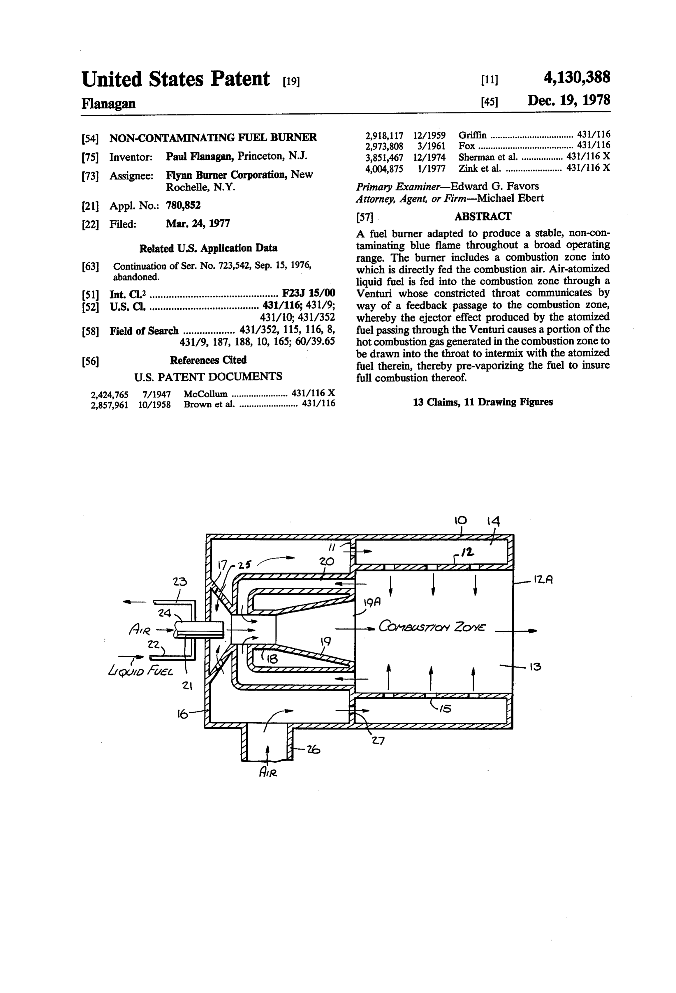
of the hot combustion gas produced in the combustion DESCRIPTION OF INVENTION zone of the burner is recirculated to pre-vaporize the atomized-liquid fuel being fed into the combustion zone, The Basic Burner Structure an adequate level of hot gas recirculation being main Referring now to FIG. 1, there is schematically tained throughout the broad operating range of the shown a blue-flame liquid fuel burner in accordance burner, even when under low fire conditions the incom with the invention making use of a gasification system in ing flow of combustion air is at a low level. which a portion of the hot combustion gas is recircu Still another object of the invention is to provide a 10 lated to ensure full combustion throughout a wide oper compact blue-flame burner of simple design which op ating range.
erates efficiently and reliably throughout its full operat The burner structure includes a cylindrical outer ing range and which may be mass-produced at low cost. casing 10 divided by a partition 11 into a forward or A self-sufficient contaminant-free burner in accor upstream section and a rear or downstream section. dance with the invention has many industrial aplications 15 Concentrically mounted within the forward section of and may be fired directly into ovens, kilns, furnaces and outer casing 10 is an inner casing 12 which defines other heating equipment. without designing a combus therein a cylindrical combustion zone 13. The annular tion zone into the equipment, thereby making possible space between inner and outer casings 10 and 12 func significant reductions in equipment size. Since combus 20 tions as a combustion air-admission chamber 14. Inner tion is virtually complete within the combustion zone of casing 12 is provided for this purpose with a circumfer the burner itself, the thermal expansion of the combus ential array of openings 15 which provide combustion tion gases affords a high exit velocity. This high exit air jets at right angles to the direction of the incoming velocity coupled with near stoichiometric flame tem pre-vaporized liquid fuel, as indicated by the arrows. In peratures assures high coefficients of convective heat 25 practice, the air jets may be inclined somewhat to pro transfer. mote recirculation.
Also an object of the invention is to provide an im Outer casing 10 is provided with a rear wall 16 to proved liquid fuel atomizer in which the liquid fuel to enclose the rear section of the burner. Supported be atomized is subjected in an internal mixing chamber therein between rear wall 16 and partition 11 is a Ven to high velocity air streams both within the central core 30 turi structure constituted by a converging inlet section of the liquid and about its periphery to effect thorough 17, a constricted throat section 18 and a diverging dif atomization of the liquid even at low atomizing air flow fuser section 19, the latter opening into combustion rates and pressures. w zone 13. A portion of the hot combustion gas generated Briefly stated, these objects are attained in a blue within combustion zone 13 is fed back into throat sec flame burner in accordance with the invention in which 35 tion 18 of the Venturi by feedback ducts 20. an atomized liquid fuel is projected by an atomizer Supported centrally on rear wall 16 of outer casing 10 nozzle wherein liquid fuel is intermixed with atomizing is an atomizer nozzle 21 to which liquid fuel is supplied air, through a Venturi into a combustion zone. Combus by an input line 22. The unused portion of the fuel is tion air is directly fed into the combustion zone, a por returned to the fuel source via a spill line 23. Also fed to tion of the hot combustion gas being fed through a nozzle 21 through an input port 24 is an atomizing air feedback passage into the throat section of the Venturi stream. The conical inlet section 17 of the Venturistruc and being drawn therein by the ejector effect of the ture may be provided with openings 25 to admit a small atomized liquid projected therein to pre-vaporize the amount of the combustion air into the inlet section to atomized liquid and thereby insure full combustion intermingle with the air-atomized liquid injected into thereof in the combustion zone. The recirculation of hot 45 the Venturi.
combustion gas is effective throughout a broad turn Extending laterally from the rear section of outer down range even at low-fire conditions in which the casing 10 is an input pipe 26 which feeds combustion air incoming flow of combustion air is at a low level. into the region surrounding the Venturi, the combustion
OUTLINE OF DRAWENGS
air being forced into air-admission chamber 14 through
SO ports 27 in partition 11. The flow path of the combus
For a better understanding of the invention as well as tion air from input pipe 26 is indicated by arrows. other objects and further features thereof, reference is In operation, air-atomized liquid fuel injected by made to the following detailed description to be read in atomizer nozzle 21 into the converging inlet section 17 conjunction with the accompanying drawings, wherein: of the Venturi structure is projected at high velocity FIG. 1 schematically shows in longitudinal section a 55 through the constricted throat section 21. The air-ato preferred basic embodiment of a blue-flame burner in Venturi mized fuel is then diffused by diffusion section 19 of the accordance with the invention; before it enters combustion zone 13 where it is FIG. 2 is a first modification of the basic burner; ignited. A portion of the resultant combustion gas from FIG. 3 is a second modification of the basic burner; the combustion zone is fed back to throat section 21 of FIG. 4 is a third modification of the basic burner; the Venturi through ducts 20 for recirculation. FIG. 5 is a fourth modification of the basic burner; In throat section 18 of the Venturi, the air-atomized FIG. 6 is a fifth modification of the basic burner; liquid fuel issuing from nozzle 21 creates an ejector FIG. 7 is a sixth modification of the basic burner; effect, causing a pressure drop and inducing entrain FIG. 8 is a seventh modification of the basic burner; ment and recirculation of the hot combustion gas taken FIG. 9 is an eighth modification of the basic burner; 65 from the output offeedback ducts 20. In this way, pre FIG. 10 schematically shows in longitudinal section a vaporizatin of the air-atomized liquid fuel takes place preferred embodiment of a liquid fuel atomizer in accor before this mixture enters the combustion zone at exit dance with the invention; and plane 19A of diffuser section. 19.
Page 8
Thus throat section 18 of the Venturi, which entrains The intermingled gaseous fuel and air-atomized liquid the recirculating hot combustion gas, constitutes a mix fuel mixture then passes through the Venturi into the ing zone to pre-vaporize the atomized fuel, the rate of combustion zone, from which a portion of the hot gas is entrainment in this zone being controlled by the mass recirculated in the manner previously described to pre flow rate of nozzle 24, its axial position, the nozzle-to 5 vaporize the air-atomized liquid fuel. Since pre-vapori Venturi throat area ratio and the available diffuser pres zation of the gaseous fuel in the FIG. 2 arrangement is sure differential as well as the dimensions of the recircu not required, the level of hot gas recirculation and en lation passages. Upon completion of the combustion trainment may be reduced in accordance with the ejec process, the combustion gas is discharged from the tor principles described in connection with FIG. 1. In burner at the output plane 12A of inner casing 12. 10 practice, one may operate this embodiment with gas The burner structure illustrated in FIG. 1 affords alone.
highly efficient combustion over a wide turn-down Second Burner Modification range to ensure blue flame, contaminant-free operation As pointed out previously, the rate of entrainment in under all operating conditions, in that adequate recircu the mixing zone within throat section 18 of the Venturi lation of the hot combustion gas to effect pre-vaporiza 15 depends on several factors including the axial position tion of the atomized fuel is maintained throughout the of the nozzle relative to the throat section. In the FIG. operating range. 3 arrangement, nozzle 32, which is centrally mounted In known types of burners in which the combustion on rear wall 16 of the outer casing is made axially shift gas is recirculated, the combustion air stream is directed able with respect to throat section 18, so that the nozzle upstream toward the combustion zone through the may be brought toward or away from the throat sec Venturi; whereas in the present invention, this air is tion, making it possible to modulate the combustion gas directly fed into the combustion zone, and the ejector recirculation rate.
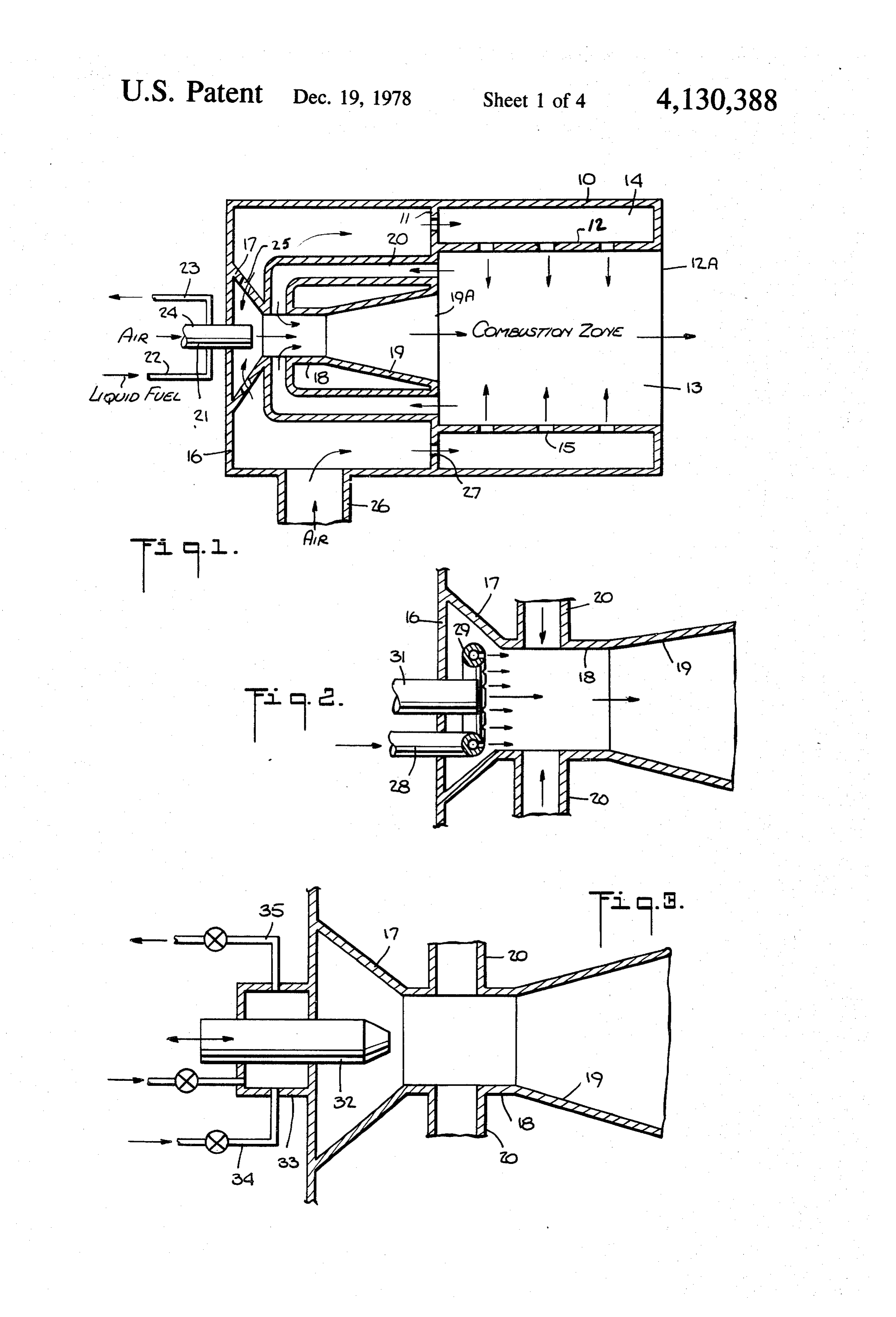
action is derived from the air-atomized fuel projecting In the FIG.3 arrangement, nozzle 32 is supplied with from the jet nozzle into the Venturi. liquid fuel and atomizing air by a distributor 33 within Consequently, even though the combustion gas pres 25 which it is slidably mounted. Liquid fuel is supplied to sure produced by the ignited fuel in the combustion distributor 33 through a fuel supply control line 34, and zone has both upstream and downstream components liquid fuel is returned to the supply through a spill line creating momentum forces, in prior burner arrange 35. Atomizing air is supplied to distributor 33 through ments, the downstream component is more or less coun an air supply control line 36. Thus with this modified terbalanced by the opposing force of the upstream 30 arrangement, one may axially adjust the position of projected combustion air stream. But in the present nozzle 32 relative to the Venturi to vary the mass flow arrangement, no such opposition is offered, and a sub rate of the recirculated hot combustion gas. stantial back pressure is developed which propels a Third Burner Modification portion of the hot combustion gas into feedback ducts In the arrangement shown in FIG. 4, the air-atomized 16. This back pressure is less substantial at the low end 35 liquid fuel is fed into a combustion zone 37 through a of the operating range when the rate of combustion air multiple bank of Venturi modules, only two of which fed into the combustion zone is at its lowest level, but (modules 38 and 39) are shown within the rear section the ejector effects of the nozzle at the low end of the of the outer casing. Each Venturi module is essentially range is sufficient to provide adequate feedback of the the same as the Venturi structure illustrated in FIG. 1 hot combustion products. and includes the necessary feedback ducts through Also, in the present arrangement, at low fire condi which hot combustion gas from the combustion zone is tions in the operating range, the air-to-fuel mass ratio in fed into the constricted throat section to pre-vaporize the nozzle is kept high, typically in excess of 10 to 1. the air-atomized liquid fuel in the manner previously This ensures excellent atomization and an adequate described.
supply of entrained hot combustion gas to promote 45 This multiple Venturi arrangement and modular de pre-vaporization of the atomized fuel. sign enlarges the capacity of the burner. In this arrange At high fire conditions, the air-to-fuel ratio in the ment, the Venturi modules are arranged about a central nozzle is low, approximately 1.5 to 1, depending upon hub 40 which projects into combustion zone 37 and is the supply pressure. Nevertheless, under these condi provided with circumferential openings to admit com tions, the combustion gas recirculation rate will be quite 50 bustion air into this zone. Thus the combustion air en adequate to effect prevaporization of the atomized fuel, ters the combustion zone, not only through air admis for the increase in fuel mass flow rate will then enhance sion chamber 14 between inner and outer casings 10 and the ejector action of the atomizer nozzle. 11, but through central hub 40 as well. The advantage Improved diffused performance is also ensured by the of this arrangement is that pre-vaporized liquid fuel present arrangement; for passage velocities are low, and 55 emitted from the diffuser sections of the several Venturi as recirculation is induced at the exit plane, flow stabil modules is intercepted in the combustion zone by com ity is increased. bustion air coming from all directions rather than only First Burner Modification from the surrounding air admission chamber 14. In some instances, it may be desirable to make use of With this multiple arrangement of Venturi modules a gaseous as well as a liquid hydrocarbon fuel. The 60 and atomized fuel injection points, one can intermit burner in accordance with the invention may be given a tently operate selected fuel injectors, using a common gaseous fuel capability by the modification of the basic combustion air supply.
structure shown in FIG. 2. In this arrangement, gaseous Fourth Burner Modification fuel is fed through input pipe 28 to a manifold ring 29 In the arrangement shown in FIGS. 1 to 4, feedback having a circular array of jet openings 30 to feed the 65 ducts 20 supply the hot combustion gas to throat section gaseous fuel into the Venturi throat section 18 to inter 18 of the Venturi directly through openings in this sec mingle with the air-atomized liquid fuel emitted by a tion. A more efficient feedback arrangement is shown in nozzle 31 coaxially disposed within ring 29. FIG. 5 wherein throat section 18 is surrounded by an
Page 9
annular shell 41 to define a common manifold therefore, for industrial applications. In most commercial and to which the outputs of all feedback ducts 20 are cou domestic installations, the requirement is for a low pled. Throat section 18 has a circumferential array of capacity burner operating in an ON/OFF manner holes 42 therein to admit the hot combustion gas in the under the control, for example, of a household thermo manifold derived from all of the feedback ducts. 5 stat, so that the burner either functions at its normal Fifth Burner Modification capacity or is turned off entirely. In the arrangements shown in FIGS. 1 to 5, all of the In such low-capacity installations, the problems at recirculated hot combustion gas is fed into throat sec tending a turn-down operation do not come into play. tion 18 of the Venturi. To enhance recirculation and to F.G. 9 shows a low-capacity fuel burner in accordance improve the performance of diffuser section 19 of the O with the invention which exploits a low exterior system Venturi, FIG. 6 shows a modified arrangement in back-pressure and utilizes the ejector action of the air which there is axial staging of the recirculation feed atomizing fuel nozzle 24 in the manner set forth in FIG. back passages. 1.
This is effected by a primary feedback duct 20 which The air-atomized fuel is projected through a Venturi directs hot combustion gas to throat section 18 to pre 15 structure mounted in the rear section of outer casing 10. vaporize the atomized liquid projected therethrough, However, in this instance, inner casing 12 is not pro and a secondary feedback duct 20' which directs hot vided with openings to feed combustion air into com combustion gas into the diffuser section 19 of the Ven bustion zone 13, nor is the required combustion air turi, thereby ensuring complete gasification of the fuel obtained from the usual secondary blower or similar before the fuel is admitted into the combustion zone at 20 means. Instead, combustion air is induced from the the diffuser exit plane 19A. ambient air surrounding outer casing 10, this air passing Sixth Burner Modification through a suitable regulating device 50 located on the In the arrangement illustrated in FIG. 1, the rela exterior of this casing.
tively cold combustion air is brought in through inlet The induced air passes into air-admission chamber 14, pipe 26 coupled to the rear section of outer casing 10 of 25 and from there enters through port 27 in partition 11, in the burner. In some instances, it may be desirable to the direction indicated by the arrows, a feedback cham intermingle this cold combustion air with warm gas ber 51 surrounding the Venturistructure disposed in the taken from the discharge flue externally coupled to the rear section of the burner. A portion of hot combustion burner. gas from combustion zone 13 is admitted into feedback To this end, as shown in FIG. 7, air pipe 26 is pro 30 chamber 51 through openings 52 in partition 11. vided at its junction with outer casing 10 with a Venturi Thus admitted into feedback chamber 51 is both hot passage 43, and flue gas is admitted into this Venturi combustion gas derived from combustion zone 13 and through a control valve 44 in an inlet pipe 45. Thus the combustion air taken from air-admission chamber 14, Venturi passage in air pipe 26 serves to induce the flue this air being cooled by the heat transfer characteristics gas therein. 35 of outer casing 10. This mixture of hot combustion gas Seventh Burner Modification and combustion air is sucked into throat section 18 of In the basic burner arrangement shown in FIG. 1, a the Venturi through holes therein as a result of the Venturi structure is disposed within the rear section of injector action of nozzle 24, the air-atomized fuel being outer casing 10 and a plurality offeedback ducts supply pre-vaporized by this recirculating hot gas. hot combustion gas to the throat section of the Venturi. 40 Improved Air Atomizers
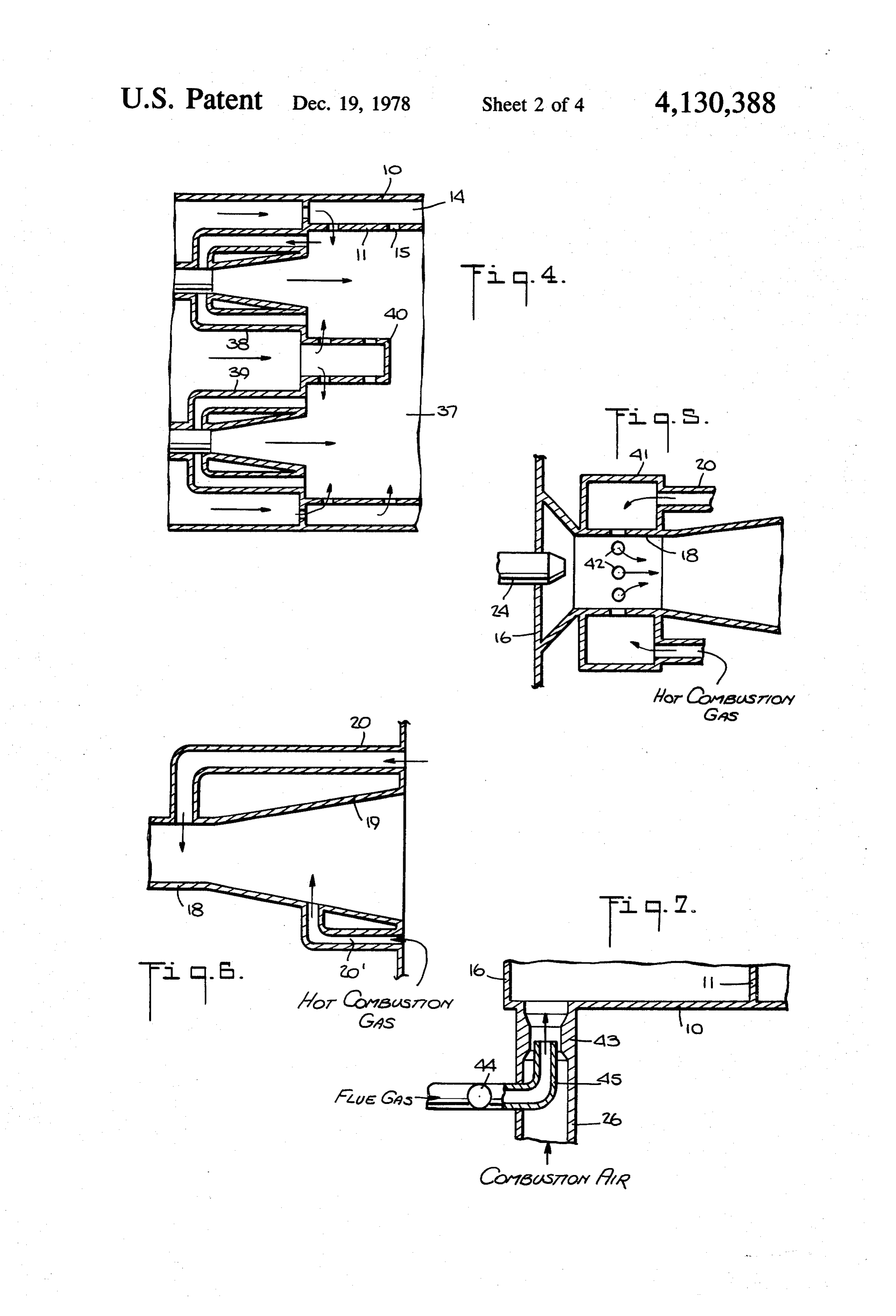
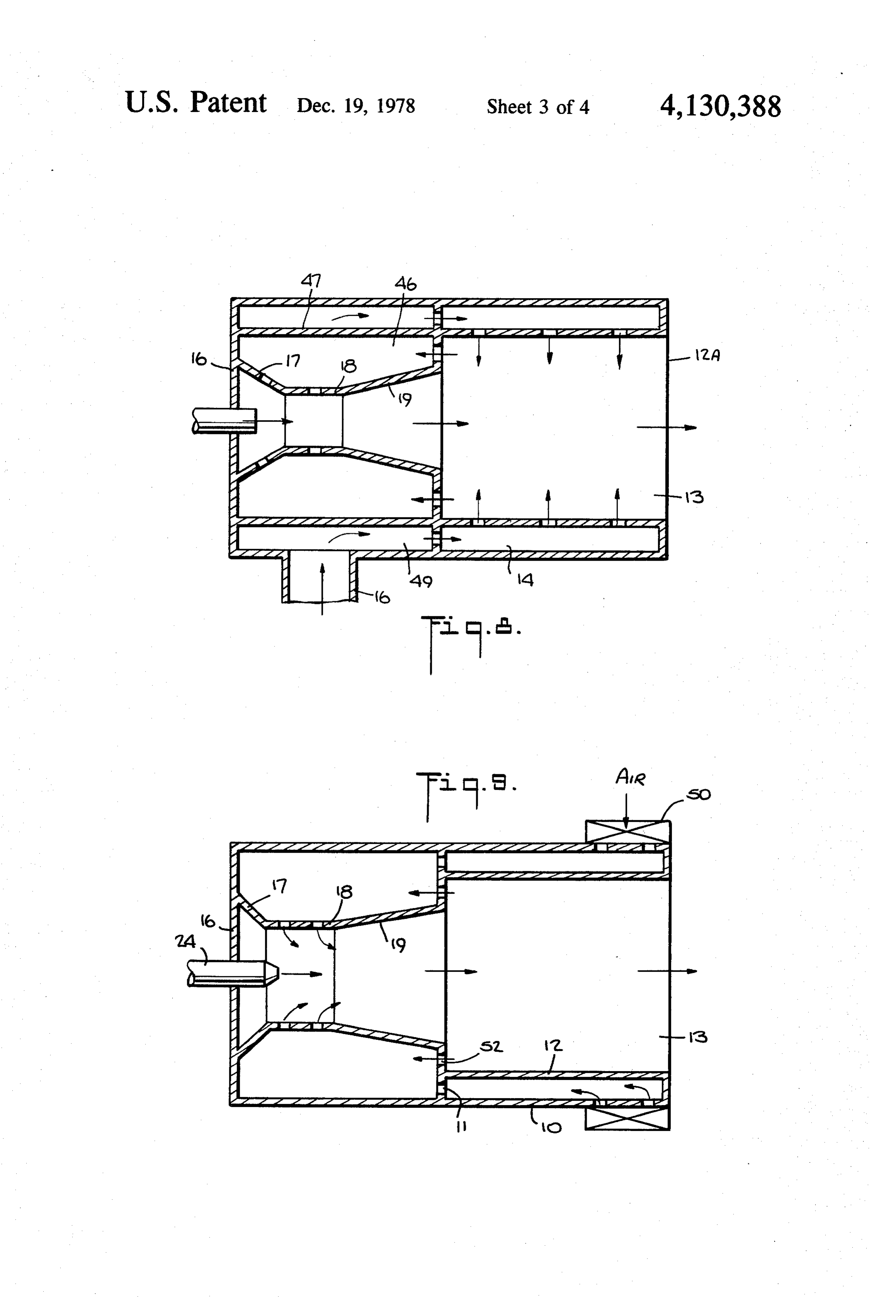
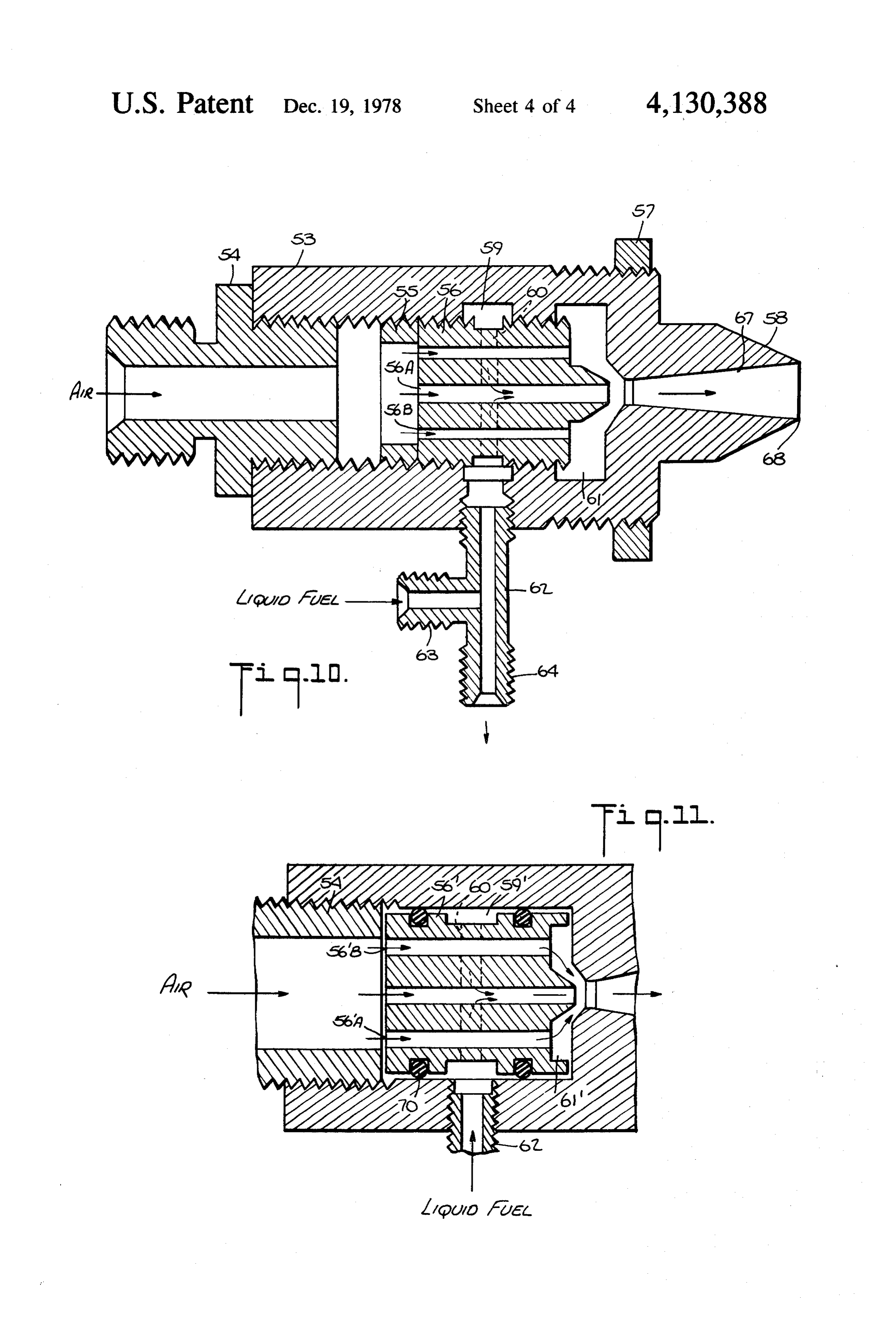
In the arrangement shown in FIG. 8, in lieu of several Referring now to FIG. 10, there is shown a liquid feedback ducts, the Venturi structure formed by inlet fuel-atomizer nozzle having internal manifolding throat and outlet sections 17, 18 and 19 is fabricated of therein to produce an air shear action on the inner core heat-resistant material. This Venturi is surrounded by a as well as on the outer periphery of the liquid fuel to be feedback chamber 46 formed by an auxiliary inner cas- 45 atomized before it is injected into the Venturi structure ing 47 concentrically disposed within the rear section of of the burner. It is to be understood that this atomizer, outer casing 10. Feedback chamber 46 communicates while it represents a preferred form of atomizer nozzle with combustion zone 13 by opening 48 in partition 11 for burners in accordance with the invention, is not which divides the outer casing. limited in its practical applications to burners of this In this modified arrangement, the space between 50 type and may be used with other forms where a high outer casing 10 and auxiliary inner casing 47 defines an degree of atomization is the desideratum. auxiliary air-admission chamber 49 which receives in The atomizer in accordance with the invention com coming combustion air from inlet pipe 16 and supplies prises a cylindrical housing 53 having an internally this air to the main air-admission chamber 14 through threaded longitudinal bore. An atomizing-air coupler 54 openings 17 in partition 11. Auxiliary inner casing 47, 55 is threadably secured to the housing and extends axially which is heated by the recirculating hot combustion from the rear thereof. Threadably received within hous gas, is cooled by the flow of combustion air which ing 53 and locked internally therein by a locknut 55 is a carries away this heat. cylindrical air-distributor 56. The forward end 53A of Thus the structure of the blue flame burner is simpli housing 53 is externally threaded to facilitate mounting fied, but in all other respects, it behaves in the same 60 of the nozzle and the adjustment of its axial position, as, manner as the structure in FIG. 1 wherein the hot com for example, on rear wall 16 of the burner shown in bustion gas fedback to throat 18 of the Venturi is drawn FIG.1. The set position of the nozzle is fixed by a lock therein by the ejector action produced by emission of nut 57. Projecting forwardly from the frontend of hous atomized liquid fuel from nozzle 24. ing 53 is a conical nose section 58 of reduced diameter Eighth Burner Modification 65 from which the air-atomized fuel mixture is emitted. The blue flame burners shown in FIGS. 1 to 8 are Formed internally within housing 53 is an annular adapted to function over a wide operating range, such channel 59 defining a liquid fuel supply manifold which burners being especially useful as high capacity burners encircles air-distributor 56. This manifold supplied fuel
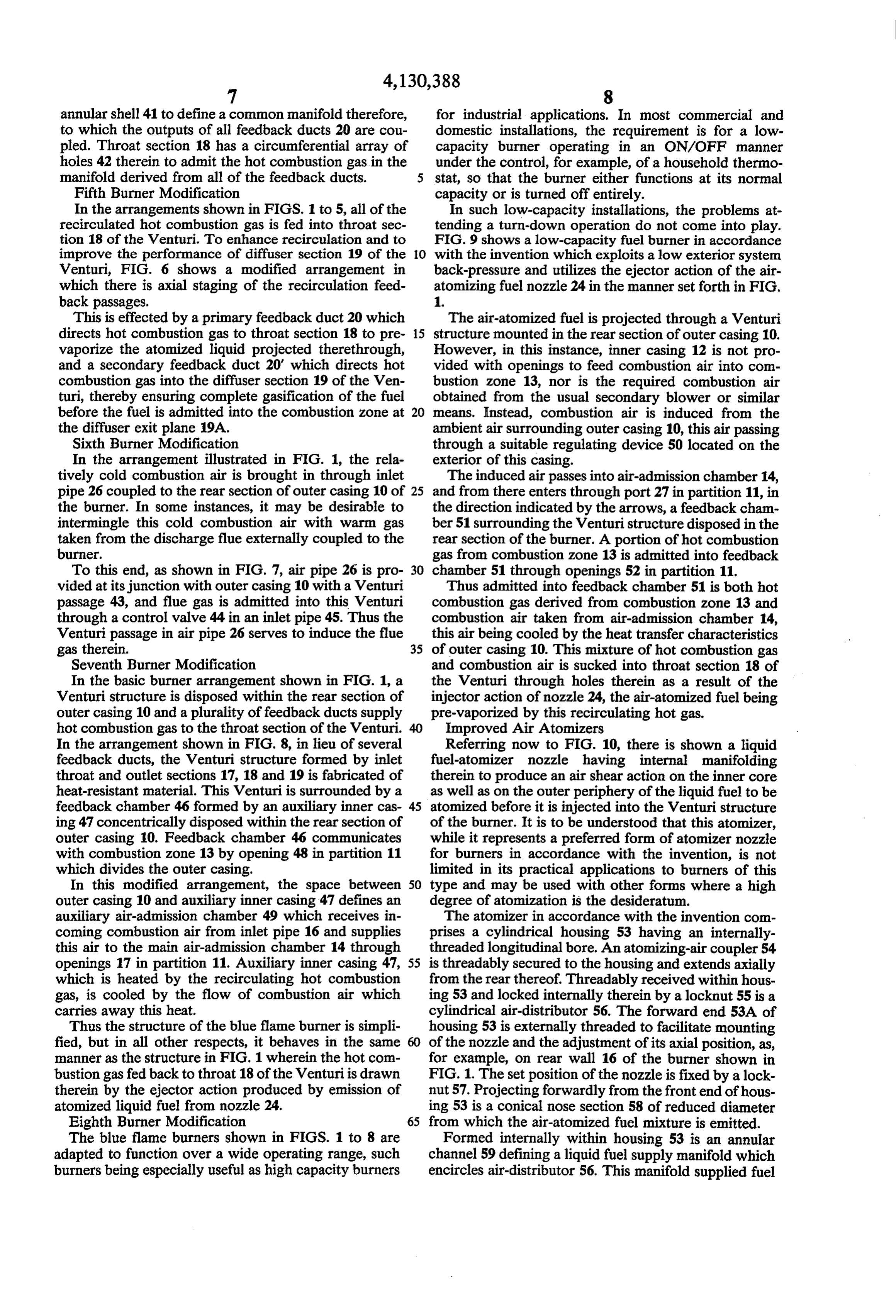
Page 10
via radial passages 60 to a longitudinally-extending adjustable in order to modulate the nozzle mass flow of central air passage 56A formed in the air-distributor. the air-fuel mixture.
Also formed in the air-distributor is a circular array of I claim:
secondary air passages 56B which surround the central 1. A liquid fuel burner adapted to promote full com air passage. The longitudinally-extending secondary air 5 bustion to produce a non-contaminating blue flame, said passages 56B serve to feed atomizing air into a second burner comprising:
ary air chamber 61 defined by the space within housing A. an outer casing having a rear section and a for 53 between the forward end of air-distributor 56 and the ward section, said forward section having a com front end of the housing. . . . .. bustion zone therein wherein a hot combustion gas Liquid fuel is supplied to fuel manifold 59 via a feed 10 is produced;
assembly 62 having a lateral inlet 63 which is coupled to B. a Venturi disposed in said rear section and having a fuel supply source and an axial outlet 64 to which a an inlet section, a constricted throat section and a spill pipe is coupled to return unused fuel to the source. diffuser outlet section opening into said combustion In operation, liquid fuel admitted into manifold 59 and conducted through radial fuel passages 60 to the 15 C.Zone; a feedback path within said rear section intercou central air passage 56A in the air-distributor is atomized pling said combustion zone with said throat section at the wall of this air passage due to the turbulent inter to conduct a portion of said hot combustion gas action of the incoming fuel and the forwardly rushing 8. thereto, said feedback path being constituted by at The intermingled liquid fuel and air emerging from 20 least one duct disposed in said rear section and the exit of central air passage 56A is projected into a extending between said combustion zone and an central mixing zone 65 formed in the conical space opening in said throat section; between the exit of this passage and sizing orifice 66 in D. means to inject into the inlet section of said Ven registration therewith. The orifice passes the atomized turi in the axial direction of the Venturi air-ato fuel into an outwardly-tapered central bore 67 formed 25 mized liquid fuel with sufficient momentum to in nose section 58 of the housing. In mixing zone 65, the produce an ejector action causing said portion of periphery of the atomized fuel stream issuing from cen hot combustion gas to be drawn into the throat tral passage 56A is subjected to the turbulent force of air section through said feedback path to prevaporize in the secondary air chamber 61 which surrounds this the air-atomized fuel whereby full combustion central stream. 30 thereof takes place in the combustion zone; Thus the outer boundary of the fuel-air mixture dis E. a supply of combustion air; and charged from the exit of the central passage 56A is F. means coupled to the supply to feed substantially subjected to secondary atomizing air and is further all of said combustion air directly into said combus atomized thereby, so that both internal and external tion zone in a direction inclined with respect to said atomization takes place within nozzle housing 53. The 35 axial direction to react with said air-atomized fuel air-atomized liquid fuel which passes through sizing to generate said hot combustion gas in said combus orifice 66 and through tapered bore 67 in nose section tion Zone and to produce a back pressure in said 58 exits from this nose section at port 68 which has a feedback path to enhance the ejector action. sharp edge creating a flow discontinuity that promotes 2. A burner as set forth in claim 1, further including turbulence and further enhances atomization. an inner casing concentrically disposed within said FIG. 9 shows a simplified version of the improved outer casing to define in the space therebetween an atomizer nozzle which operates on essentially the same air-admission chamber for combustion air, the inner principles as that shown in FIG. 8. But instead of pro casing having holes therein to pass the combustion air viding a housing which must be machined or otherwise into said combustion zone.
fabricated to define a fuel manifold and a secondary air 45 3. A burner as set forth in claim 2, wherein said rear chamber, the air distributor 56 in this instance is so and forward sections are defined by a partition disposed formed as to define an annular manifold 59' to which within the outer casing, and wherein said combustion fuel is supplied by the liquid fuel feed assembly 62, the air fuel being conducted to central air passage 56A by Venturi is fed from a supply into the region surrounding said in the rear section and is conducted therefrom radial passages 60, as in the previous version of the 50 to the air-admission nozzle. Secondary air chamber 61 between the air-dis chamber through openings in said tributor and the front end of the housing is created by partition.
4. A burner as set forth in claim3, having an opening undercut lugs 69.
No use is made of a locking nut, for the air-distributor in said inlet section of the Venturi to admit a relatively is locked in place in this instance by the input air cou 55 small amount of combustion air from said region into pler 54 whose front end is brought against the rear end said Venturi.
of the distributor. Sealing of the distributor is effected 5. A burner as set forth in claim 1, wherein said atom by O-rings 70 which encircle the distributor on either izer means is constituted by a nozzle having a liquid fuel side of fuel manifold channel 59'. input and an atomizing-air input, the incoming liquid While there have been shown and described pre and air being internally mixed in said nozzle to produce ferred embodiments of non-contaminating blue-flame said air-atomized liquid fuel.
fuel burners in accordance with the invention, it will be 6. A burner as set forth in claim 5, wherein said nozzle appreciated that many changes and modifications may is surrounded by a ring having jet openings therein from be made therein without, however, departing from the which a gaseous fuel is expelled to intermingle with the essential spirit thereof. For example, in the atomizer 65 air-atomized liquid fuel.
shown in FIG. 10, instead of maintaining a fixed rela 7. A burner as set forth in claim 5, wherein said nozzle tionship between the air distributor 60 and the nose is axially shiftable relative to said inlet section of the section 58, the distance therebetween may be made Venturi to adjust the ejector effect.
Page 11
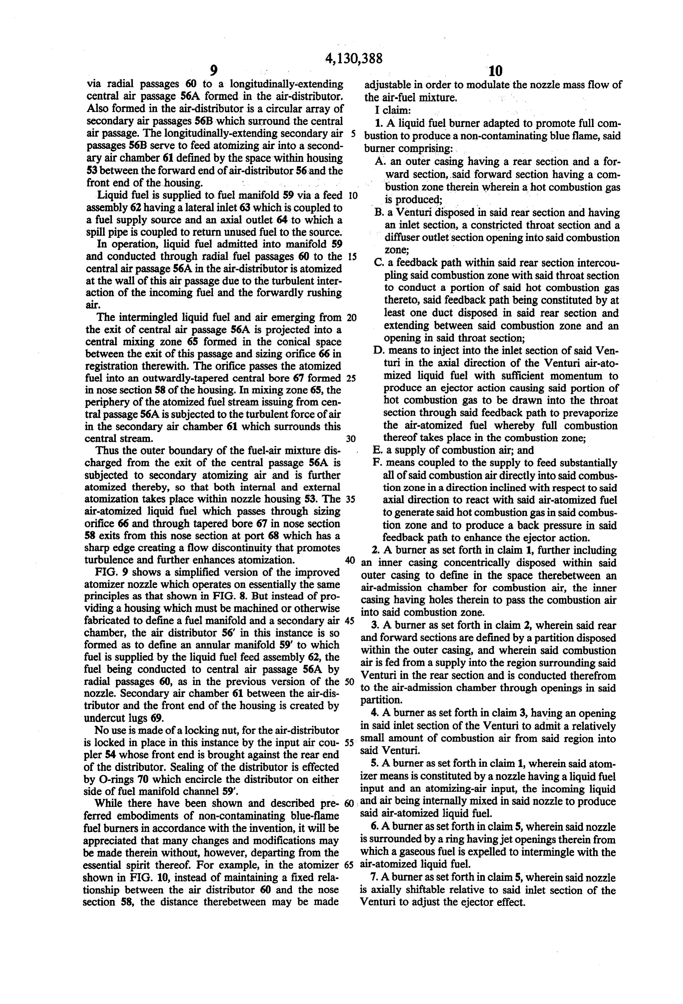
8. A burner asset forth in claim 7, wherein said nozzle hot combustion gas derived from the combustion zone is disposed within a manifold to which liquid fuel and into the diffuser section of the Venturi, atomizing air is supplied. 12. A burner as set forth in claim 1, wherein a plural 9. A burner as set forth in claim 1, wherein said feed ity of like Venturi modules are disposed in said rear back path is constituted by a plurality of ducts, each of 5 section, each cooperating with fuel injection means to which terminates in a manifold surrounding openings in project multiple streams of pre-vaporized fuel into said combustion zone.
said throat section. 13. A burner as set forth in claim 1, wherein said 10. A burner as set forth in claim 1, further including Venturi in said rear section of said outer casing is sur means to add to the combustion air which is fed into the O rounded by an auxiliary inner casing to define therein a combustion zone flue gas derived from a flue external to feedback chamber which communicates with the com the burner. bustion zone and is coupled to openings in said throat 11. A burner as set forth in claim 1, wherein said section.
feedback path includes means to feed a portion of the
Page 12
UNITED STATES PATENT OFFICE
CERTIFICATE OF CORRECTION
Patent No. 4, 130,388 Dated December 19, 1978
Inventor(s) Paul Flanagan
It is certified that error appears in the above-identified patent and that said Letters Patent are hereby corrected as shown below: Column l, line 2 "fuel" 2nd occurrence, should have read
Column 4, line 66 "vaporizatin" should have read -- vaporization -- signed and Sealed this
Sirth D ay of Mar 1979
SEAL
Attest:
Attesting Officer Commissioner of Patents and Trademarks
Provenance
- Collection
- Cited prior art
- Original PDF
- patentimages.storage.googleapis.com →
- Filed
- 1977-03-24
- Pages
- 12
- Method
- pdftotext (the PDF's own text layer) + pdftoppm 300dpi page scans
- Source
- Google Patents bibliographic record
- Granted
- 1978-12-19
- Inventors
- Paul Flanagan; FLYNN BURNER CORP
- Transcribed from
- patentimages.storage.googleapis.com →