patent · US5388985
Burner assembly with fuel pre-mix and combustion temperature controls
14 February 1995
Page 1 — bibliographic record
United States Patent (19) 11 Patent Number: 5,388,985 Musi et al. (45) Date of Patent: Feb. 14, 1995 54) BURNER ASSEMBLY WITH FUEL PRE-MDX FOREIGN PATENT DOCUMENTS
AND COMBUSTION TEMPERATURE
CONTROLS 2123945 2/1984 United Kingdom . (75) Inventors: Joseph E. Musil, Ely, Iowa; Primary Examiner-Larry Jones Lawrence G. Clawson, Dover, Mass. Attorney, Agent, or Firm-Simmons, Perrine, Albright & Ellwood 73) Assignee: Cedarapids, Inc., Cedar Rapids, Iowa
A burner assembly has a combustion chamber in which 22) Filed: Dec. 22, 1992 combustion takes place in an elongate centrally dis (51) Int. C. .............................................. F23L 13/00 posed combustion tube. An outer housing encases the (52) U.S.C. ........................................ 431/116; 431/2; combustion tube and provides an annular space between 431/12; 431/350 an inner wall of the housing and the combustion tube.
(58 Field of Search ....................... 431/116, 2, 4, 5, 8, Part of the exhaust gases exiting from the combustion 431/9, 12, 115, 350, 254 tube are diverted from the downstream end thereof to
References Cited be returned through the annular space to the upstream 56 end of the combustion tube. Fuel is injected into the
Re. 29,496 12/1977 Dydzyk. and mixed with the diverted gases. The fuel and gas 3,652,194 3/1972 Bailey. mixture is further combined with a buffer gas and be 3,705,784 12/1972 Reichheim et al. . comes entrained into and mixed with a high velocity of 4,298,337 11/1981. Butler et al. . combustion air which is injected into the upstream end 4,600,377 7/1986 Musil . of the combustion tube. The flame temperature may be 4,995,807 2/1991 Rampley et al. ....................... 431/9 monitored and the quantity of the buffer gas added may 5,092,761 3/1992 Dinicolantonio . be controllably varied based on temperature readings 5,102,328 4/1992 Robinson . from the monitoring process to minimize the generation 5,145,359 9/1992 Anacona et al. . of nitrous oxides.
5,275,554 1/1994 Faulkner ............................. 431/9 X 19 Claims, 4 Drawing Sheets
Page 2
Drawing sheet — no readable text.
Page 3
Drawing sheet — no readable text.
Page 4
Drawing sheet — no readable text.
Page 5
Drawing sheet — no readable text.
Page 6
units, such as turbo-burners used for drying aggregate
BURNER ASSEMBLY WITH FUEL PRE-MEX AND products, appear to be related to non-uniformities in the COMBUSTION TEMPERATURE CONTROLS distribution of combustion elements within the combus tion mixture. If, within the mass of the mixture, each
BACKGROUND OF THE INVENTION 5 droplet is regarded as a discrete fuel source, then a 1. Field of the Invention region about each droplet becomes a discrete combus This invention relates generally to burner assemblies tion region which contributes incrementally to the and more particularly to burner assemblies with provi overall combustion process.
sions for injecting liquid fuel and dispersing the fuel 10 On a molecular scale, each such fuel droplet, no mat within combustion air. ter how small, constitutes a concentration of a great 2. Discussion of the Related Developments number of fuel molecules with respect to surrounding Burner assemblies, for example those that may be oxygen molecules (O2) in the fuel to air mixture. It used for aggregate drying operations, are frequently appears that within the brief period during which com operated with industrial types of liquid fuels, such as a 15 bustion takes place, the combustion of such local fuel burner grade diesel oil or even special heating oil of a molecule concentrations brings about respective local grade heavier and more viscous than diesel oil. State-of Zones of oxygen depletion, resulting in a tendency of the-art turbo-burner assemblies include fuel induction some fuel elements not being able to combine with systems which disperse the liquid fuel in form of fine oxygen while the bulk of the gases undergo combustion. droplets into a stream of combustion air and allow the 20 The present invention addresses the described prob fuel droplets to mix with the air before the mixture of lem of nonuniform combustion and of resulting air pol fuel and air is ignited and burned. lutants by first volatilizing liquid fuel and then mixing Combustion of the fuel takes place only after the fuel the in each of the droplets is vaporized. The smaller the gen volatilized supplied by fuel with stoichiometric amounts of oxy an appropriate amount of combustion droplets of fuel, the more uniformly and efficiently the air. Combustion takes place in a "standing flame' region
combustion appears to proceed. In state-of-the-art fuel of a burner assembly only 'atomizing' or dispersion provisions, small droplets of the air become fully intermixed. after the volatilized fuel and A substantially blue the fuel become interspersed with the combustion air. flame combustion process may be obtained by substan As a mixture of fuel droplets and the combustion air tially complete mixing of the fuel and combustion air. It moves toward the "flame region' of the burner, the heat of the standing flame begins to vaporize the fuel. 30 has been found that it is possible to apply the described The smaller the droplets, the greater is the surface area sequence of steps to high capacity burners for aggregate of the droplets in relation to its mass volume and the material type dryers and the like, to obtain a blue flame faster is the rate at which the fuel vaporizes. Once the and, therefore, substantially complete combustion of a fuel is vaporized, combustion of the fuel occurs with supplied fuel without a need to add excess oxygen. stoichiometric amounts of oxygen supplied by the com 35 However, even when combustion takes place with pre bustion air. However, combining a measured quantity mixed fuel and oxygen gases, the tendency of the com of liquid fuel with combustion air having a stoichiomet bustion gases to form nitrous oxides still needs to be rically correct supply of oxygen is typically found to controlled.
result in incomplete combustion and in emissions of In light of the above considerations relating to the hydrocarbons and unburned oxygen. With the addition 40 invention and to the problems to be addressed by the of excess air, such as is done in state-of-the-art systems, invention, it is an object of the invention to provide a to raise the oxygen supply above that of the stoichio burner assembly with a device for volatilizing liquid metric oxygen, more complete combustion results and fuel and for mixing the volatilized fuel with stoichio the hydrocarbon content in the emission products tends metric amounts of oxygen before igniting the fuel and to decrease. But, the more complete combustion also 45 oxygen mixture in a combustion region of the burner results in higher flame temperatures and undesirable assembly.
nitrous oxides tend to appear in increasing concentra Another object of the invention is to provide a burner tions in the emitted combustion gases. Ideal combustion assembly which includes a provision for separating a results in a "blue flame” combustion. Though optimiz portion of the hot combustion gases from a mainstream ing adjustments in the fuel to air ratio are made, experi 50 of combustion gases and a provision for mixing liquid ence shows that some unburned hydrocarbons remain fuel with the separated hot combustion gases to carry and some nitrous oxides (NO) are generated during the combustion process. The generation of nitrous oxides the liquid fuel within the separated gases during the typically occurs in excessive amounts at flame tempera volatilization
A further of the fuel.
object of the invention is to provide a tures above 2,200 degrees Fahrenheit. 55 burner assembly with a capability to entrain a heated
The emission into the atmosphere of either hydrocar gas and fuel at a predetermined rate within a stream of bons or nitrous oxides is in any case undesirable and combustion air.
may, if the emission of either hydrocarbons or nitrous oxides is excessive, violate prescribed clean air require burner Yet another object of the invention is to provide a ments. With increased public awareness of the desirabil 60 at which assembly with an adjustment for changing a rate ity of limiting air pollution, a continuing need exists for a hot, oxygen depleted combustion gas and improvements in existing commercial burner systems to volatilized fuel becomes entrained into the stream of further reduce the levels of undesirable emissions of atmospheric combustion air. hydrocarbons or nitrous oxides or both. It is another object of the invention to provide a 65 controlled amount of oxygen depleted buffer gas to mix
DISCUSSION OF THE INVENTION with volatilized fuel and become dispersed throughout Problems with controlling concentrations of pollut a stream of combustion air to limit the generation of ing products in emissions from "high capacity' burner nitrous oxides.
Page 7
It is yet another object to provide a burner for the DETAILED DESCRIPTION OF THE homogeneous combustion of fuel in a controlled envi INVENTION ronment resulting in the generation of reducing com bustion gases or products. 1. The Burner Assembly
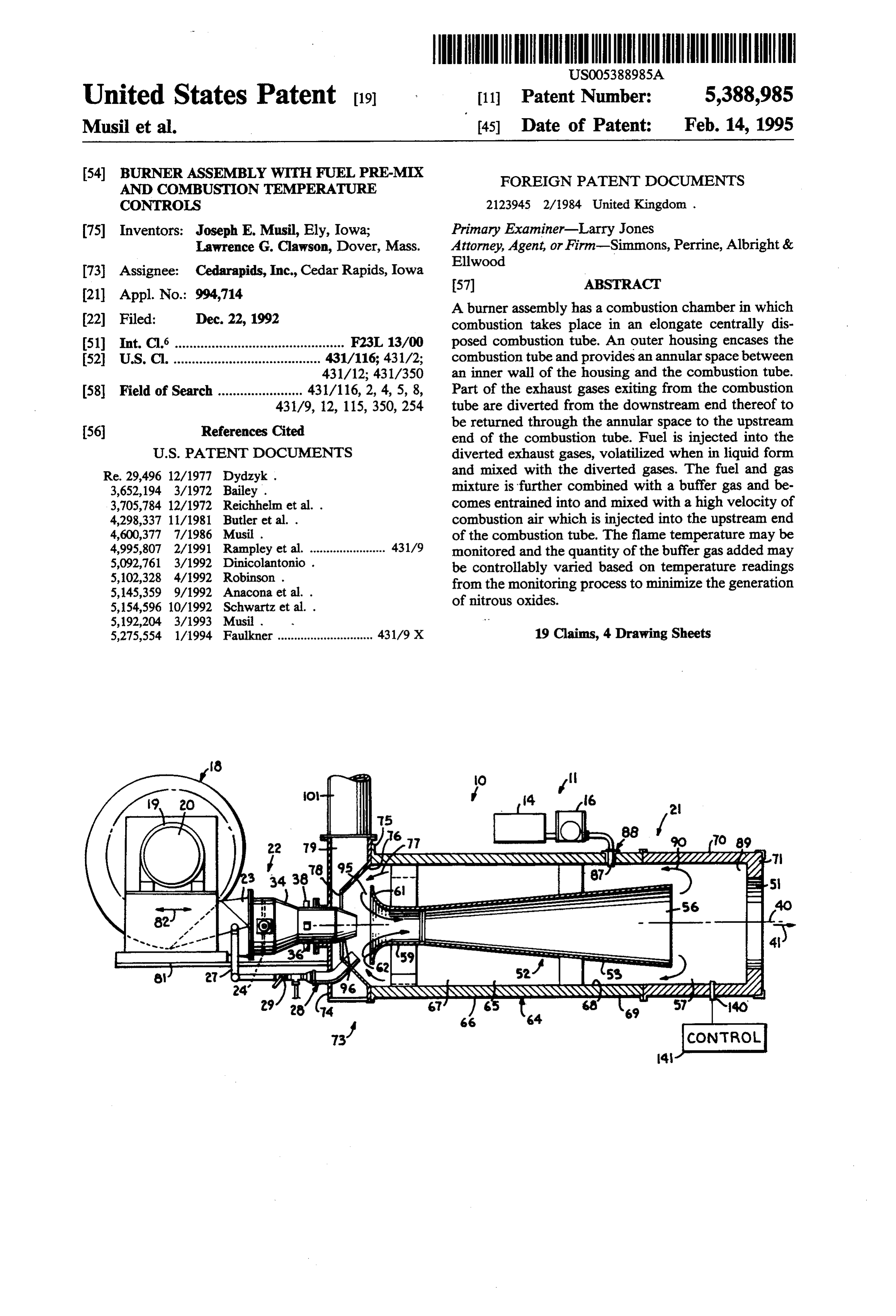
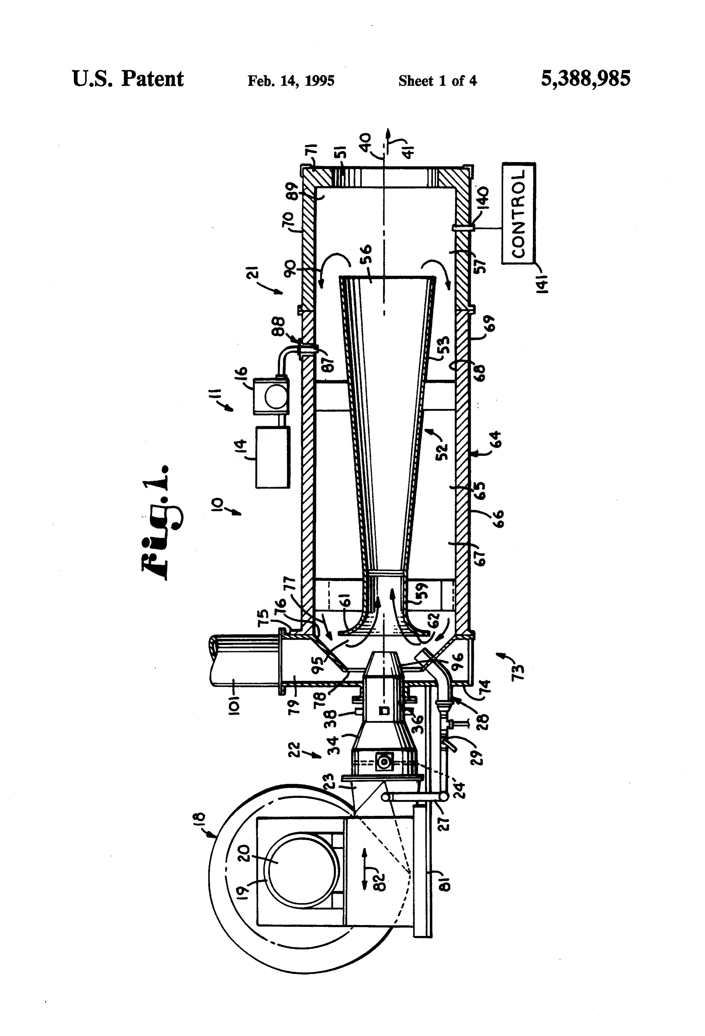
Various advantages and features of the invention in 5 FIG. 1 shows a cross section through a burner assem accordance herewith will become apparent from the bly designated generally by the numeral 10. The burner further description of the invention and from the de assembly is a major component of a burner system 11. scription of the described preferred embodiments The burner system 11 described herein as an embodi thereof which may be read in reference to the appended ment of the invention may be a "high capacity' burner drawings. 10 system having an energy generating capacity of at least
SUMMARY OF THE INVENTION
twenty million BTU (British Thermal Units), and as high as two hundred million BTU, such as is typical for
In accordance with the invention, a burner assembly heating bulk products such as aggregate materials in an includes an elongate combustion chamber. A combus asphalt production plant, as shown schematically in tion tube is disposed centrally and extends longitudi 15 FIG. 2.
nally within the combustion chamber. The burner as In reference to FIG. 1, the burner system 11 includes sembly includes a blower assembly for generating a the burner assembly 10, a fuel supply shown schemati stream of combustion air through the combustion tube. cally at 14, a fuel metering and injection pump 16. The A provision for generating a mixture of fuel and oxygen burner assembly 10 is characterized as a turbo-burner for homogeneous combustion in the combustion tube 20 assembly and includes a turbo-blower 18 for providing includes a provision for injecting fuel into a stream gas a stream of primary combustion air. The turbo-blower including heated combustion gases to volatilize the cally 18 includes a housed, centrifugal fan 19 which is typi injected fuel. A provision disposed at the entrance of trifugaldriven by an electric motor 20. The housed, cen fan 19 is capable of moving a substantial volume the combustion tube entrains the mixture of the injected 25 of air with a substantial pressure head with respect to fuel with oxygen depleted heated gas into the stream of ambient, combustion air entering the combustion tube. atmospheric air. As an example, a turbo According to one aspect of the invention, the mixture mum energy18generating blower unit of a burner assembly 10 having a maxi capacity of two hundred mil of fuel and oxygen may be controlled to vary over a lion range of mixtures from an excess of fuel vapor, to a 30 cubic foot of airper minuteadvance,
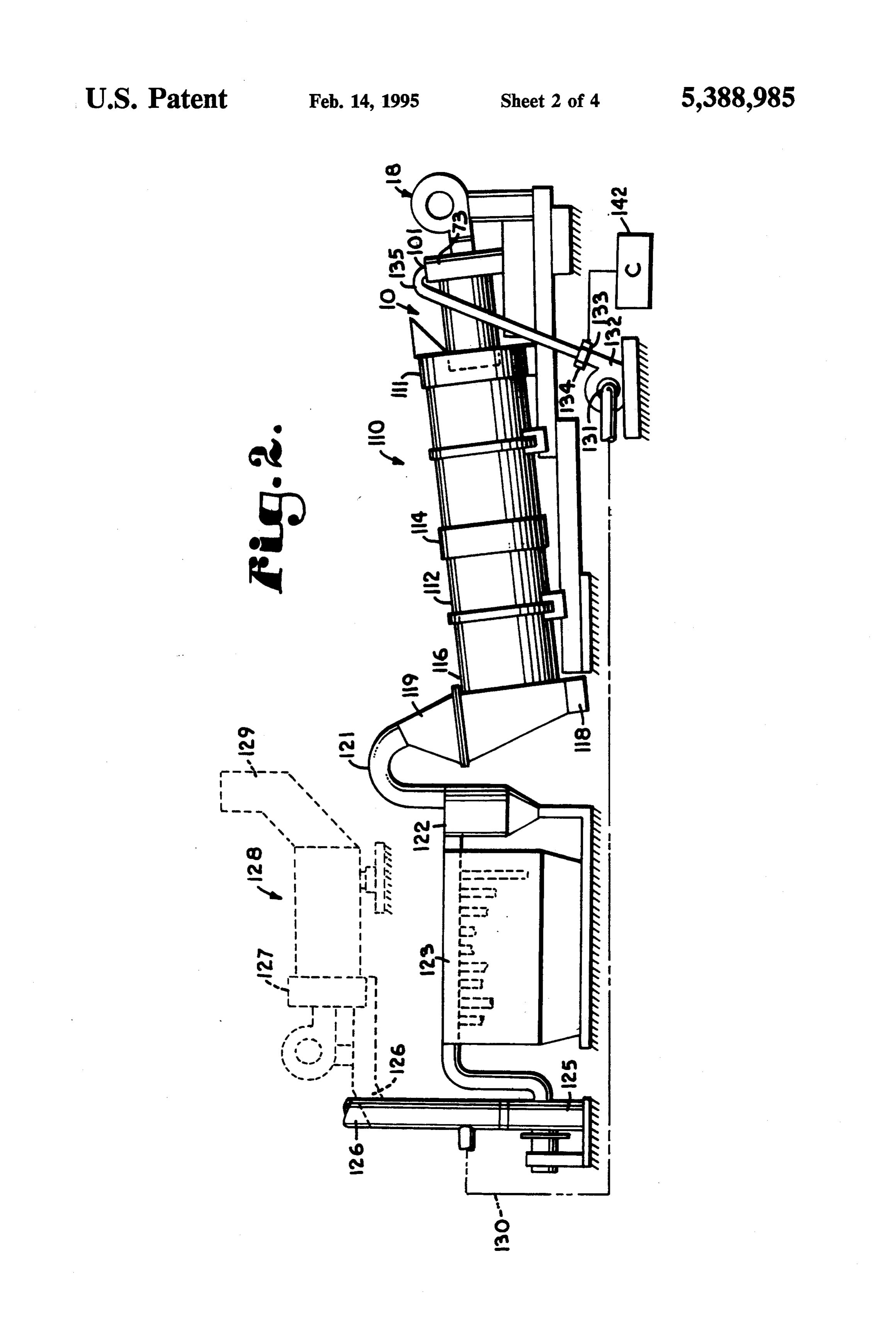
stoichiometric mixture, or even to a mixture including ounces per square inch to a atcombustion a pressure of up to thirty chamber 21 of an excess of combustion air. When burned in accor dance with the provisions, generation of undesirable to an outlet 23 of the turbo blower unit 1822directs the burner assembly 10. A transition section coupled air pollutants, such as nitrous oxides, is controlled. into the combustion chamber 21. A turbo air damper 24 According to another aspect of the invention the 35 is disposed within the transition section 22. The damper provision for entraining pre-burned combustion gases 24 is preferably an adjustable shutter type damper and is with unburned fuel and turbo combustion air includes a venturi flow generator at the entrance of the combus used to control the supply of combustion air to the combustion chamber 21. Another function of the tion tube. An annular opening adjacent the flow genera damper 24 is to generate a pressure drop of combustion tor for admitting and entraining the pre-burned gases is air preferably adjustable to generate a desired stoichiomet the atairthedirected outlet of the turbo blower 18 with respect to into the combustion chamber 10. The ric mixture of volatilized fuel and oxygen within the pressure head of the combustion air as sustained at the combustion tube. outlet 23 from the turbo blower may be used, as shown BRIEF DESCRIPTION OF THE DRAWENGS with respect to the described embodiment, to supply 45 combustion air through a supply pipe 27 to a pilot
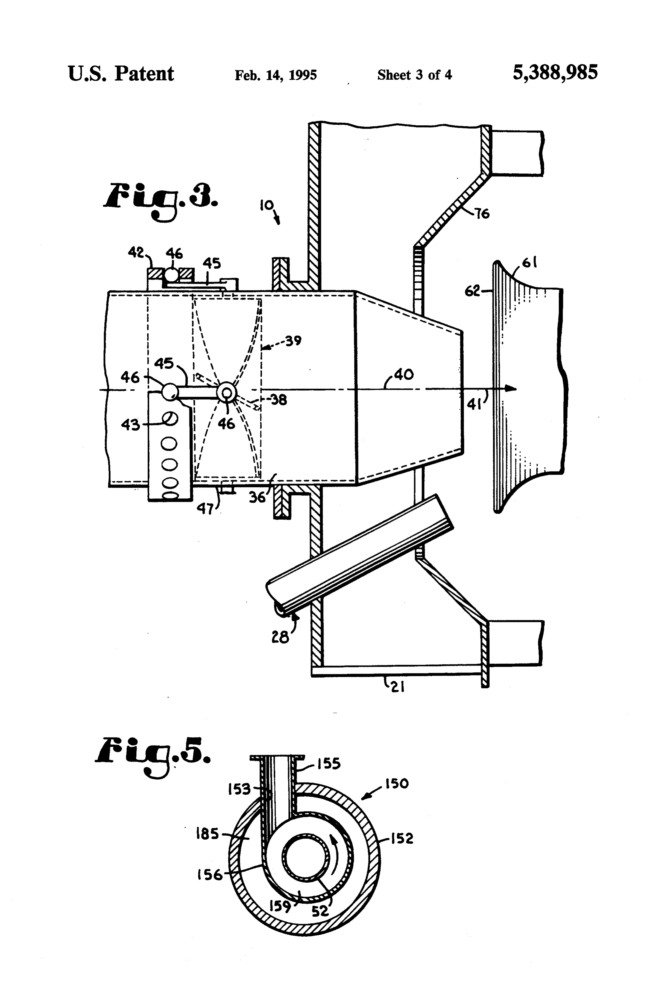
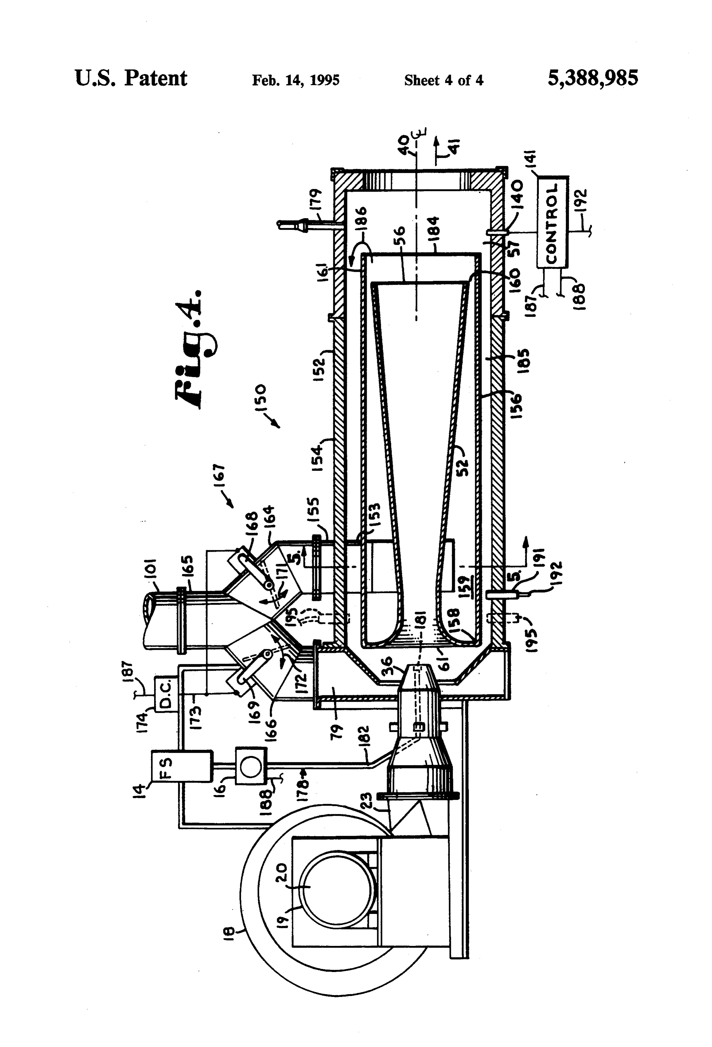
The Detailed Description below may be best under burner assembly 28. The pilot burner assembly 28 in stood when read in reference to the accompanying cludes a typical air shutoff valve 29, a preferred LP fuel drawings wherein: type pilot flame holder 31 and a pilot flame injector tube FIG. 1 is a simplified sectional view through a burner 32. The transition section 22, according to the described assembly of a burner system which incorporates fea SO embodiment, may include a flow converging section 34 tures of the present invention; ahead of an air injector nozzle 36 which further in FIG. 2 is a schematic representation of an aggregate creases the exit velocity of the combustion air as it exits drying apparatus as a preferred example of an environ through the air injector nozzle 36 into the combustion ment to which the present invention advantageously chamber 21. The described structure of the turbo applies, the schematic representation showing particu 55 blower 18 consequently generates a high velocity lar features of the present invention, and showing also stream of combustion air which is injected in a highly an alternate embodiment which includes a desirable directional stream into the combustion chamber 21. afterburner; Referring to FIGS. 1 and 3, stator type spin vanes 38 FIG. 3 is an enlarged partial view of the burner as of a spin vane assembly 39 are in a preferred embodi sembly shown in FIG. 1, showing an upstream end of 60 ment radially disposed within the air injector nozzle 36 the burner assembly in greater detail; to impart to the combustion air a component of rota FIG. 4 is a simplified sectional view through a burner tional motion about a longitudinal axis 40 of the burner assembly similar to that of FIG. 1 but with certain mod assembly 10 just before the air exits into the combustion ifications relating to mixing combustion air and pre chamber 21. A pitch angle of the spin vanes 38 with burned buffer gases with fuel; and 65 respect to the axial flow direction (see arrow 41) of the FIG. 5 is a sectional view taken at "5-5' in FIG. 4 combustion air may be adjustable by a single ring 42 and showing details of a duct device for introducing disposed about the air injector nozzle 36. The ring 42, as buffer gas into the burner assembly of FIG. 4. shown in FIG. 3, has a plurality of circumferentially
Page 8
spaced circular bearing seats 43. An outer end 44 of an ledge or wall 71 closes off a radially outermost portion adjustment arm 45 is retained by each of the seats 43. of the downstream end of the combustion chamber 21. Each respective one of the adjustment arms is pivotally An upstream end 73 of the outer housing 64 of the attached to an adjustment shaft 46 of a corresponding combustion chamber 21 is capped off by an intake and outer end of each of the spin vanes 38. The adjustment return shroud 74. The shroud 74 may be preferably shaft 46 protrudes through an outer shell 47 of the air attached circumferentially to a flange 75 of the outer injector nozzle 36. housing 64. Besides sealing off the upstream end 73 of The combustion chamber 21 of the burner assembly the outer housing 64 and, hence, of the combustion 10 is, in the embodiment of FIG. 1, an elongate cylindri chamber 21, the shroud 74 serves two other major func cal vessel within which the fuel and combustion air 10 tions. A frustum type conical wall 76 of the shroud 74 become mixed, the mixture is ignited and the combus does close off a substantial annular portion of the up tion process is substantially completed. Thus, within the stream end of the combustion chamber 21. However, confines of the combustion chamber 21, the hot gases the conical wall 76 also functions as a guiding surface are generated which then exit from the chamber 21 15 for turning a flow of gases from the annular space 65 through an exit port 51 to perform a heating function, toward the opening 62 of the combustion tube, as indi such as heating and drying aggregate materials, for cated by an arrow 77 in FIG.1. A central opening 78 in the conical wall 76 has a diameter greater than an outer example. It is to be understood that as long as the com diameter bustion gases maintain the energy level close to the injector of the air injector nozzle 36. Thus, with the air flame temperature, disassociations and recombinations 20 opening 78nozzle 36 extending centrally through the among elements of combustion may still continue on a opening 78 remainsof the shroud 74, an annular space of the limited scale. Hence, the "plume' of what constitutes chamber 79 of the shroud to 4 communicate between an ante 74 and the combustion cham the flame may extend through the opening 51 as the ber 21. The turbo blower unit 18 may be slidably burned gases exit at high velocity from the combustion mounted on an adjustment frame 81 to be moved into a chamber 21.
A combustion tube 52 is disposed longitudinally 25 desirable one of various adjustment positions in a direc tion along the longitudinal axis 40 of the burner assem within the combustion chamber 21 and is centered on the longitudinal axis 40. The combustion tube has a bly 10 either away or toward the opening 62 of the combustion tube 52, as indicated by an arrow 82 in FIG.
generally conically shaped wall 53 which tapers out 1. A preferably flanged opening 85 slidably receives the ward in the direction of the gas flow through the com 30 air injector nozzle 36 of the turbo blower 18. An annu bustion chamber 21. An exemplary workable angle of lar seal 86 preferably closes off a sliding clearance be taper of the conical wall 53 is seven degrees of taper tween the air injector nozzle 36 and the opening 85. with respect to the longitudinal axis 40. Reasonable Sliding the blower unit 18 toward the combustion tube deviations from such a taper will be found acceptable or may even be desirable in configuring the shape of a 35 52 tends to decrease the quantity of diverted heated gases which return through the annular space 65 to combustion tube. A downstream or end 56 of the tube become entrained in the high velocity stream of com 52 terminates with its opening at a normal flame region bustion air exiting from the air injector nozzle 36. 57 of the combustion chamber 21. A central throat A preferred liquid fuel supply system is shown in portion 59 of the combustion tube 52 may be generally FIG. 1 by the fuel reservoir 14 and the fuel metering cylindrical in shape, while at an upstream end 61 the and injection pump 16. Various systems for introducing combustion tube 52 terminates in a curved outward liquid fuel into a burner are known, most of which flared bell with an opening 62 similar to the front por include provisions for "atomizing' the fuel, hence, for tion of a trumpet. The material of the combustion tube dispersing fuel in form of fine droplets into a stream of 52 is a inch thick, high temperature resisting stainless combustion air. The location for introducing liquid fuel steel (312L). The diameter of the preferably circular 45 is selected to allow for substantial vaporization of the section of the combustion tube 52 at the downstream fuel before it is moved to the flame region 75 within the end 56 is substantially less than an inner diameter of an combustion chamber 21. The liquid fuel to supply the outer housing 64 of the combustion chamber 21. The burner assembly 10 is injected, preferably also in the difference in dimensions of the combustion tube 52 and form of droplets, through a typical injection tube 87 of the outer housing 64 result in an annular enclosed space SO an injector assembly 88 into the annular region 65 be 65 along the length of the combustion tube 52. A major tween the combustion tube 52 and the 4 outer housing wall portion 66 of the outer housing 64 encasing a front 64. The injector assembly is preferably removably region 67 of the chamber 21 may be of a compound, mounted to the outer housing 64 to extend through the fiberglass insulated stainless steel wall structure. An wall of the outer housing 64 into the combustion cham inner wall 68 of preferably inch thick 316L type stain 55 ber 21. Alternate positions for injecting the liquid fuel less steel sheet is outwardly surrounded by an insulating into the combustion chamber 21 may be selected, partic material 69 that may be commercially obtained under ularly since the position of the injector assembly 88 as the trade designation “Carborundum Fiberfax'. A rear shown in FIG. 1 provides the longest possible path or downstream wall portion 70 of the outer housing 64 before the injected fuel reaches the desired flame region encases the flame region 57 and is subjected to the hot 60 57.
flame and the hot combustion gases as they exit from 2. The Operation of the Burner Assembly the combustion tube 52. The downstream wall portion Further in reference to FIG. 1, the ledge 71 forms 70 of the outer housing 64, consequently, would consist with the remaining downstream wall portion 70 of the preferably of "green castable' ceramic tile material. outer housing 64 an annular stagnation region 89 about The exit port 51 at the downstream end of the wall a main flow volume of the combustion gases exiting portion 70 of the outer housing 64 is smaller in diameter from the downstream end 56 of the combustion tube 52 than an inner diameter of the cylindrical wall portion and advancing through the flame region 57 out of the 70, such that an annular ledge 71 is formed. The annular combustion chamber 21. The stagnation pressure of the
Page 9
gases in the annular region 89 is believed to contribute combustion gases may be desirable only for fuels with to a diversion of a portion of the combustion gases highest in a range of volatilization temperatures. In emanating from the end 56 into the annular region 65 jected fuel is heated immediately by the diverted gases between the combustion tube and the outer housing of and becomes vaporized, the process of vaporization the combustion chamber 21. The beginning of the flow 5 requiring energy. The energy is taken from the diverted pattern of the diverted portion of the combustion gases gases, the energy transfer tending to lower the tempera is indicated by arrow 90. A reverse flow pattern of the ture of the diverted gases. However, any standing flame diverted gases with respect to the general flow in the within the combustion tube tends to heat the wall por direction of arrow 41 of the combustion gases is fur tion 53 of the combustion tube 52 and supply further thered by a venturieffect in an entrainment region 95 at O energy to the evaporating fuel and the returning gases. the upstream opening 62 of the combustion tube 52. The The position of the fuel injection assembly 88 as shown venturi effect entrains the pre-burned diverted gases in FIG. 1 may be advantageous primarily for fuel oils and the injected fuel into stream of combustion air. The with extreme vaporization energy requirements. For trumpet-shaped flare of the upstream or front end 61 liquid fuels having a lower vaporization temperature or interacts with the conical wall 76 and a preferably con 15 requiring less energy to vaporize, the location of the vergingly tapered front end 96 of the air injector nozzle fuel injection assembly 88 may advantageously be 36 to guide the pre-burned recirculating gases and the shifted closer toward the upstream opening 62 of the fuel into the combustion tube 52. The relatively high combustion tube 52. It is desired that after injection of velocity of the stream of combustion air enhances a the liquid fuel and after it has been at least partially venturi effect by the combustion air as it exits from the vaporized, the temperature of the mixture of fuel and air injector nozzle 36 and enters the front end 61 of the gases in the annular region would remain below the combustion tube 52. combustion temperature of the fuel. Incomplete com An adjustment of the axial position (in the direction bustion of the diverted gases and the mixture of fuel of the longitudinal axis 40) of the front end 96 of the air may have resulted in a substantial depletion of free injector nozzle 36 changes a cylindrical surface area 25 oxygen within the volume of the diverted gases within about the stream of combustion air entering the com the annular region 65. However, the raised temperature bustion tube 52. The extent of the cylindrical area re of the fuel, hence the energy state of the fuel, renders lates to the amount of the diverted gases that become the injected fuel ready for combustion, except for the entrained within the combustion air exiting from the air substantial absence of available oxygen from the mix injector nozzle 36. The entrainment of the diverted 30 ture of vaporized fuel and the diverted gases. On be gases lowers the gas pressure in the annular entrainment coming entrained in the combustion air and contacting region 95 to further induce a return flow of diverted the oxygen molecules of the air, combustion of already gases from the annular region 65 about the combustion vaporized fuel is readily initiated. Any remaining liquid tube 52 into the tube in the direction of the main stream fuel vaporizes as the combustion air and fuel travels of combustion air and gases through the tube 52. The 35 toward the flame region 57. The velocity of the com hot, diverted gases are not merely used to further the bustion air in the throat portion 59 exceeds the flame vaporization of injected fuel. The diverted gases also progression speed or velocity of the combustion pro function as a buffer medium to disperse the fuel mole cess, causing the flame to occur away from the air injec cules and to enhance mixing of the fuel with combustion tor nozzle 36 at a standing flame position adjacent the air. The travel from the injector assembly 87 to the downstream end 56 and within the combustion tube 52 entrainment region at relatively low gas velocity com proper.
pared to the velocity of gas flow through the combus Nitrous oxide generation in the combustion process tion tube 52 provides significant time or distance within may be controlled by adding a carbon monoxide rich which the fuel droplets or fuel gas molecules may be buffer gas to the mixture of the diverted gas and the come dispersed throughout the diverted gases. The 45 volatilized fuel as described herein. The antechamber 79 reverse flow with respect to the flow direction of the is coupled to a supply duct 101 through which such a combustion gases (see the arrow 41) in essence provide buffer gas may be supplied to the mixture of the volatil a flow length for such dispersion of fuel within the ized fuel and the diverted combustion gas. A forward combusted gases which doubles the length of the com adjusting movement of the air injector nozzle 36toward bustion tube 52 to achieve maximum dispersion. The 50 the combustion tube 52 tends to choke off the extent of reverse flow length may be used when the overall the diverted gas flow through the annular region 65. length of the combustion chamber 21 is for space rea Without a change in the rate of the fuel injection, the sons kept at a minimum and the injected fuel has added fuel to gas mixture becomes enriched, however the time to disperse and volatilize before reaching the flame buffer gas entering the entraining region from the ante region 57. 55 chamber 79 through the opening 78 supplements the gas The physical state of the diverted gases needs to be being entrained into the stream of combustion air exit considered in locating the fuel injector assembly 88. ing from the air injector nozzle 36. The buffer gas may The referred to angle of the combustion tube 52 is such be oxygen poor or depleted, cleaned exhaust gas, a that under normal burner settings and gas flow settings, pre-burned gas which may be diverted from the exhaust the beginning of the flame region is sustained well 60 of an aggregate heating process as shown in FIG. 2. toward the end of the downstream tapered portion 53 of 3. An Industrial Application of the Burner Assembly the combustion tube 52. Thus, combustion of the fuel The described burner assembly 10 is applied advanta and air mixture would be still in progress as the combus geously to any one of a number of industrial process tion mixture and gases exit from the combustion cham applications, as, for example, a soil decontamination ber 21. The diverted gases are at substantially their 65 process or an aggregate drying operation, shown sche highest temperature as they enter the annular space 65 matically in FIG. 2 as an example. A parallel flow drum between the combustion tube 52 and the outer housing dryer and mixer apparatus 110 is shown. At a raised, 64. Injection of the fuel into the hot diverted stream of upstream end of the apparatus 110 the burner assembly
Page 10
10 is axially aligned with and directed through an mate The presence of the afterburner 128 is desirable rial feed port 111 into a typical, rotatably mounted when, for example, carbon monoxide containing buffer drum 112. Additional material of a more heat sensitive gases are intentionally present in the exhaust to mini disposition, such as recycle aggregate, may be added via mize explosion hazards during the use of the exhaust as an intermediate feed port 114 to the material already in 5 a drying or heating gas. Carbon monoxide functions as the drum 112. Adjacent a discharge end 116 of the drum a reducing gas in processes which for example seek to the material would be mixed with liquid asphalt and the vaporize combustible materials, such as hydrocarbons. mixed product be discharged as hot asphalt mix through Vaporization of hydrocarbons may be expected to some a discharge port 118 at the discharge end of the appara degree in asphalt production processes, and in larger tus 110. Exhaust gases from the summarized operation 10 quantities in soil remediation processes. In soil remedia are drawn off through an exhaust chamber 119 also burner tion processes the heat of the combustion gases from the immediately downstream of the discharge end 116 of bons assembly 10 may be used to remove hydrocar the drum 112. Ducting 121 routes the exhaust gases from decontaminated soil. routinely through a primary dust separator, such as a FIG. 2 shows schematically a contemplated arrange cyclone separator 122 and from there to a state-of-the 15 ment for routing a buffer gas through the duct 101 fur art filter house 123. Substantially all entrained dust or ther with structural elements which interact advantageously the burner assembly 10 and the burner system 11 of material particles which may have become entrained within the gas stream passing through the apparatus 110 the apparatus 110 as a whole. FIG. 2 shows schemati will be removed by the sequential application of the 20 cally an exhaust gas supply line 130 leading from the primary dust separator 122 and the filter house 123. An fan 132. stack exhaust
126 to a central intake port 131 of a turbo exhaust port 133 of the turbo fan 132 a exhaust blower 125 draws the filtered gases from the damper assembly 134 regulates the external recircula filter house 123 and advances the gases toward typical tion flow of exhaust gases. Preferably, the damper as exhaust ducting 126. In one embodiment of the inven sembly 134 controls on a real time basis the extent to tion, the exhaust ducting 126 may be an exhaust stack 25 which cooled exhaust gases may be added through a 126 venting the filtered gases to the atmosphere. Partic feed duct 135 to the combustion air forced into the ulate matter is removed from the gases at this time. The burner assembly 10. The turbo fan 132 allows the exhaust has cooled substantially from its initial, heated state, and is considered clean except for the possibility cooled above recirculated or exhaust gases to be forced at atmospheric pressure into the upstream end 73 of of the existence of unburned hydrocarbon gases and 30 the combustion chamber. The forced recirculation is nitrous oxides that might have been generated. The preferably matched with the forced supply of turbo generation of these gaseous pollutants, however, is combustion air from the turbo blower 18. The feed duct thought to be minimized or substantially avoided by the 135 is coupled directly to the supply duct 101, commu features of the burner assembly 10 as described herein. nicating, therefore, with the antechamber 79 formed by As an alternate routing of exhaust gases from the 35 the shroud 73 as described with respect to FIG.1. Thus, filter house 123, the ducting 126 may lead directly to an the externally recirculated, cool, pre-burned exhaust antechamber 127 of a second burner assembly 128. The gases which are added as a buffer to the combustion air second burner 128 is referred to as an afterburner 128. are preferably added under the pressure or force gener The afterburner 128 as used in a commercial process as ated by the turbo fan 132. On the other hand, the described herein, burns combustible elements from ex 40 heated, internally recirculated or diverted combustion haust gases before they are released into the atmo gases are added by becoming entrained at a pressure less sphere. These combustible elements may be carbon than the stagnation pressure of the combustion gases in monoxide or even residual hydrocarbon vapors. The the stagnation region 89 of the combustion chamber. afterburner 128 may be any of a number of suitable Further in reference to FIG. 1, a temperature probe 140 types of second burner assemblies. The burner 128 may 45 may extend into the flame region 57 to measure the be structurally similar to the described burner assembly temperature of the flame on a continuous basis. The 10 or to an alternate burner assembly as described temperature probe 140, consequently, would be cou below with respect to FIGS. 4 and 5, though it could be pled to a control console shown schematically at 141. a typical state of the artburner. The hot gases which are The control console 141 (“CONTROL') may either be generated by the operation of the burner assembly 10 SO coupled to, or be integrated into, a damper control 142 perform, after their generation, a function in an indus (“C”) which is shown schematically in FIG. 2. The trial process, such as heating, drying or vaporizing pol damper control 142 permits a quick response in altering lutants, one of the functions being described with re the quantity of the externally recirculated or cooled spect to FIG. 2. The purpose of the burner 128 is to exhaust buffer gases in response to a change in a me cleanse the exhaust gases of unburned elements. Thus, 55 tered amount of fuel injected into the burner assembly after being drawn from the antechamber 127 into the 10 by the pump 16. Thus, an increase in the amount of combustion chamber of the burner 128, the exhaust fuel desirably results in an immediate increase in the gases mix with the combustible mixture of fuel and quantity of combustion air and in the quantity of recir combustion air and are passed through the flame of the culated buffer gases to maintain the flame temperature afterburner 128. The combustion gases emanating from 60 within a desired range of temperatures. Further adjust this latter combustion process are already clean and ments in the quantity of the cooled externally recircu need not pass through any further filter and are released lated buffer gases may be made when temperature devi from the burner 128 through an exhaust chamber-stack ates from the desired range of flame temperatures as assembly 129 to the atmosphere. Some cooling may registered by the temperature probe 140 shown in FIG. occur within the exhaust chamber and stack assembly 65 1. The desired range of flame temperatures lies prefera 129. Except for such minor initial cooling, the exhaust bly below 2700 degrees Fahrenheit, above which tem from the afterburner 128 is directly released to the at perature the generation of nitrous oxides appears to mosphere. increase. An acceptable range of flame temperatures
Page 11
within which no corrective adjustments would be made Energy from recirculated gases is used to vaporize might lie, for example, between 2100 degrees and 2500 fuel during the path of injected fuel from the atomizing degrees Fahrenheit. nozzle 181 to the flame region. Mixing recirculated, 4. Buffer Recirculation Cooling preheated gases with recirculated cool gases at a con FIG. 4 shows a modification of the burner assembly trollable ratio allows the energy level of the mixed 10, the modified burner assembly being designated gen precombustion gases and fuel to be optimized. Recircu erally by the numeral 150. It is sought to further im lated gases introduced through the gas supply duct 155 prove control over nitrous oxide generation without cool the combustion tube 52, the downstream extension compromising "blue flame” characteristics of the 161 of the combustion tube 52 and the wall of the com burner assembly 10. The burner assembly 150 includes a O bustion chamber 152.
combustion chamber 152 similar to the combustion The routing of the cooling gases is best explained in chamber 21 previously described. The combustion reference to FIGS. 4 and 5. Referring to a section chamber 152 further provides an access port 153 through the burner assembly 150 and particularly the through an outer housing 154 to admit a gas supply duct combustion chamber 152, as shown in FIG. 5, the gas 155. The combustion tube 52 centered within the outer 15 supply duct 155 is coupled to introduce recirculated and housing 154 is additionally encased along its length by a cooled combustion gases radially offset or tangentially cylindrical jacket 156. The annular enclosed space 65 into the gap or space 159 between the combustion tube along the length of the combustion tube 52 is thereby 52 and the jacket 156. The introduced gases spiral at modified to a space between the outer housing 154 and high velocity within the annular gap 159 about the the jacket 156. The gas supply duct 155 extends through 20 combustion tube 52 toward the annular opening 160 at the port 153 and communicatively opens into the jacket the downstream end 56 of the combustion tube 52. Cen 156. The jacket 156 is sealed against an outer rim 158 of trifugal forces tend to cause classification of materials the upstream flared opening 62 of the combustion tube including fluids and gases, more dense materials being 52, such that the cylindrical jacket 156 and the combus forced radially outward less dense, hence, hotter gases tion tube 52 form a unitary subassembly within the outer 25 spiral in circumferentially stratified regions closer to the housing 154. An annular gap 159 between the combus center of revolution. Thus, the recirculating gases, tion tube 52 and the jacket 156 functions as a cooling gas though being heated by the flame of burning fuel and conduit. The annular gap 159 decreases in width toward gases within the downstream extension 161 of the com the downstream end 56 of the combustion tube 52. The bustion tube 52, nevertheless remain at a lower tempera annular gap 159 leads to an annular opening 160 at the 30 ture with respect to other gases of the combustion pro downstream end 56 of the combustion tube 52. The cess within the flame region at the downstream exten jacket 156 extends in length past the end 56 of the com sion 161. The recirculating gases, consequently, con bustion tube 52, forming a downstream extension 161 of tinue to spin spiral along the inner wall of the down the combustion tube 52. stream extension 161 toward the end 184 of the jacket The gas supply duct 155 is coupled to a first branch 35 156. Spinning past the end of the jacket 156 the recircu 164 flow divider duct section 165. A second branch 166 lated cooling gases, now already heated, enter the annu of the divider duct section is coupled to the antecham lar space between the outer housing 154 of the combus ber 79. Both the antechamber 79 and the gas supply tion chamber 152 and the jacket 156, designated as a gas duct 155 are thereby coupled to the gas supply duct 101 return flow space 185, in a return flow pattern indicated which receives cooled combustion gases, as described by arrow 186. As long as the gases remain at a tempera with respect to the structure shown in FIG. 2, through ture below that of wall portions heated directly by the a supply line 130, for example. The divider duct section flame, the gases absorb energy from those wall portions. 165 preferably includes a flow regulating damper ar Continuing to spiral about the flame of the burning rangement 67 which may include first and second gases, the cooling gases absorb energy directly from the dampers 168 and 169 as shown in FIG. 4, or a single 45 burning gases to perform a cooling function while in damper 169 in the branch 166 may be used. The damp creasing in energy to provide to liquid fuel which is ers may be separately operable as indicated by the ar introduced through the atomizing nozzle 181 into the rows 171 and 172. A control linkage or operating ar stream of combustion gases.
rangement 173 may be a mechanical actuating mecha Not all of the cooling gases introduced through the nism or an electromechanical, hydraulic or pneumatic 50 duct 155 may be returned to the upstream end 61 of the operating arrangement, schematically shown at 173. combustion tube 52, since there is necessarily some The operating arrangement would be actuated by con mixing. However, qualitatively, the now heated cooling trol inputs from a damper control system 174 which is gases introduced through the duct 155 are substantially schematically represented by the function box "D.C.'. the heated gases which are returned through the annu The burner assembly 150 is further distinguished 55 lar return flow space 185 to the upstream end 61. It from the previously described burner assembly 10 by a should be understood that the spiralling direction of the relocated fuel injection system 178 and a relocated pilot cooling gases downstream toward the opening 160 is burner assembly 179. The fuel injection system 178 less significant than the inherent characteristic of re preferably has a fuel atomizing nozzle 181 disposed maining substantially in tact as a separate gaseous mass centrally within the air injector nozzle 36. The fuel because of the centrifugal motion. These gases, intro supply 14 and the fuel metering pump 16 are coupled duced for cooling and to be heated, remain nevertheless through typical fuel lines 182 to the atomizing nozzle cooler than the flame temperature. The centrifugal clas 181. The burner system 150 allows for vaporization and sification permits the gases to be returned substantially mixing of fuel with the combustion gases along the as an intact and separate, heated combustion gas (rich in route of the gases and fuel from the air injector nozzle 65 carbon dioxide, yet deficient or poor in free oxygen) to 36 to the flame region 57. Premature ignition is mini transfer its energy to any liquid fuel to vaporized the mized by locating the pilot burner assembly 179 directly fuel in its path toward the flame region 57. The cooling within the flame region 57 of the burner assembly 150. gases not only cool the combustion tube 52 but also
Page 12
contribute to reduce the flame temperature in boundary combustion air exiting from the air injector nozzle 36 heat transfer with the flame in the flame region 57. with an increased surface area capable of entraining and Other arrangements for introducing a cool, substan mixing with the fuel and recirculating gases. Thus, a tially inert gas into the flame region to reduce the aversubstantially complete mixture of the fuel elements and age flame temperature. For example, the gases might be the oxygen in the combustion air may be present at the introduced tangentially directly into the flame region 57time when the combustion process is initiated. of the burner assembly 150 and spiral at high speed As an alternate location for fuel injection, instead of counter to the burning gases to enter an annular space having the atomizing nozzle 181, fuel injection nozzles and be returned to the upstream end of the combustion 195 may be peripherally spaced within the outer hous tube 52. However, the described arrangement is pres 10 ing 154 adjacent the upstream end of the Combustion ently more expedient. tube 52, as shown in phantom lines in FIG. 4. The in The damper control 174 may be used to control a jected fuel would then be mixed with the heated gases ratio of cool recirculated gases entering the combustion just before becoming entrained in and mixed with the tube 52 through the antechamber 79 and preheated high velocity stream of turbo air injected into the up recirculated gases entering the combustion tube 52 15 stream end 61 of the combustion tube 52. through a preheating loop of the gap 159, and the space Various other changes and modifications in the struc 185. Under preferred settings, the preheated, recircu ture of the described embodiment are possible without -lated gases would provide volatilization energy to cause departing from the spirit and scope of the invention as substantially all atomized fuel in the combustion mix defined by the terms of the claims appended hereto and ture to vaporize on mixing with the recirculated gases 20 reasonable equivalents thereof. and prior to reaching a standing flame in the flame What is claimed is:
region 57 of the burner assembly 150. Volatilization and 1. A burner assembly comprising: mixing of the fuel preparatory to combustion begins a combustion chamber including an outer housing with the step of dispersing the liquid fuel from the atom and an inner, elongate combustion tube disposed izing nozzle 181 as a mist of small droplets into the 25 spacedly from and centrally within the outer hous stream of turbo combustion air passing through the air ing, the outer housing forming an annular enclosed injector nozzle 36. The small droplets of fuel begin to space along the length of the combustion tube, the vaporize with energy drawn from the stream of com combustion tube having upstream and downstream bustion air. Further volatilization energy is supplied by ends;
the heated, recirculated gases which become entrained 30 a flame region extending from the downstream end of into and mix with the stream of combustion air and the the combustion tube into the outer housing of the fuel at the upstream end 61 of the combustion tube 52. combustion chamber;
The quantity of heated recirculated air is adjusted to means for injecting a high velocity stream of combus provide the energy needed to vaporize the fuel droplets tion air into the upstream end of the combustion on their way to the flame region 57. The total quantity 35 tube to flow through the combustion tube in a of recirculated air is adjusted to lower the flame temper direction toward the flame region of the combus ature in the flame region 57 to a temperature at which tion chamber;
the generation of nitrous oxides remains at a level to means for injecting liquid fuel into the combustion meet requirements. The damper control 174 and the chamber to be entrained in and become mixed with control console 141 may be communicatively coupled the combustion air before the combustion air enters or integrated. The control console 141 (“CONTROL') the combustion tube;
is the master control of the burner which would have a an exit opening formed in the outer housing down control connection 187 to the damper control 174 as a stream of the downstream end of the combustion subcircuit, and a control connection 188 to the fuel tube, the exit opening being bounded peripherally metering injection pump 16. Other temperature probes 45 by a pressure increasing ledge for diverting heated may be used to monitor and control the vaporization of combustion gases from the flame region of the fuel and the energy input to the burner assemblies 10 combustion chamber to flow counter to the direc and 150. In the burner assembly 150, an exemplary tion of flow in the combustion tube through the temperature probe 191 is coupled via a control line 192 annular enclosed space about the combustion tube to control console 141. The temperature of the heated 50 toward the upstream end of the combustion tube; recirculated combustion gases may be measured to flow directing means at the upstream end of the com compute together with a known flow rate from the bustion tube and communicating with the annular damper adjustment a total available energy rate from space about the combustion tube for directing the the recirculated gases. The energy rate may be varied diverted combustion gases from the annular space when the fuel input to the burner assemblies 10 or 150 55 to become entrained in and mixed with a stream of are charged at the control console 141. combustion air injected into the combustion tube; 5. Other Variations of the Described Embodiments and
The described structure of the burner assemblies 10 means for combining and mixing a buffer gas with and 150 may be further modified without departing diverted combustion gases to become entrained in from the scope of the invention. Mixing of the combus and mixed with the stream of combustion air and tion air and the fuel may be enhanced by causing a spin with combustion fuel, the diverted combustion in the combustion air in any number of ways. The ad gases providing energy for vaporizing the combus justable spin vanes for generating a flow component in tion fuel prior to burning the mixture of combus the combustion air in a plane transverse to the general tion air and fuel in the presence of the mixed buffer direction of flow along the axis 40 may be replaced by 65 gas within the flame region of the combustion another arrangement. For example, the tapered front chamber.
end 96 of the air injector nozzle 36 may be fluted or 2. The burner assembly according to claim 1, wherein otherwise shaped to increase the surface area of the the means for combining and mixing the buffer gas
Page 13
comprises means for measuring the flame temperature downstream end of the combustion tube, the introduced in the flame zone of the combustion chamber, and combustion gases circulating along an inner wall of the means for controlling the quantity of the buffer gas to jacket, thereby cooling the extended jacket and absorb be entrained in and mixed with the combustion air to ing energy from burning fuel within the flame region. maintain the flame temperature within a predetermined 11. The burner assembly according to claim 9, further range of temperatures. including means for monitoring the temperature of the 3. The burner assembly according to claim 1, wherein diverted combustion gases prior to becoming entrained the means for injecting liquid fuel is located so that the in and mixing with the stream of combustion air. liquid fuel is injected into the heated diverted combus 12. A burner assembly comprising: tion gases and becomes entrained in and mixed with the O a combustion chamber including therein an elongate combustion air together with the heated combustion combustion tube having upstream and downstream gases. ends, the combustion chamber having a flame re 4. The burner assembly according to claim3, wherein gion within a downstream end portion of the com the means for combining and mixing the buffer gas bustion tube and extending downstream beyond comprises means for measuring the flame temperature 15 the downstream end;
within the flame zone of the combustion chamber, an means for directing a high velocity stream of combus adjustable damper for controlling the quantity of buffer tion air from the upstream end through the com gas, and means for adjusting the damper in response to bustion tube;
a deviation of a measured flame temperature from a means for returning heated gases from the flame re desired temperature range. 20 gion to the upstream end of the combustion tube; 5. The burner assembly according to claim 1, wherein means for mixing liquid fuel and returned, heated the means for injecting liquid fuel is located so that the gases with the combustion air at the upstream end liquid fuel becomes dispersed into the stream of com of the combustion tube, whereby energy from the bustion air and the heated diverted combustion gases heated gases is transferred to the liquid fuel to are entrained into a mixture of combustion air and dis 25 vaporize the liquid fuel prior to the liquid fuel persed liquid fuel to vaporize the fuel. being carried by the stream of combustion air to the 6. The burner assembly according to claim 1, com flame region; and prising a cylindrical jacket disposed about the combus a cooling jacket disposed about the combustion tube, tion tube and forming an annular cooling conduit with the coolingjacket bounding an annular space about the combustion tube, the annular cooling conduit hav the combustion tube and including means for re ing an annular opening adjacent the downstream end of ceiving and centrifugally spiraling cooling gases . the combustion tube, and means for introducing cool through the annular space and along the flame recirculated combustion gases tangentially into the region thereby cooling the combustion tube and cooling conduit to move in a circular path about the heating the spiraling gases, and for transferring combustion tube toward the annular opening, thereby 35 heated cooling gases to the means for returning becoming heated while cooling the combustion tube, heated gases from the flame region to the upstream the pressure increasingledge diverting the heated com end of the combustion tube. bustion gases into the annular enclosed space. 13. The burner assembly according to claim 12, 7. The burner assembly according to claim 6, wherein wherein the means for directing a high velocity stream the means for combining and mixing an oxygen defi of combustion air through the combustion tube com cient buffer gas is a means for combining and mixing prises a turbo-burner assembly including an air injection cool recirculated combustion gases, the means includ nozzle having a nozzle opening directed into the up ing a flow divider coupled to a cool combustion gas stream end of the combustion tube.
supply, the flow divider having a branch duct coupled 14. The burner assembly according to claim 13, fur to the means for introducing cool recirculated combus 45 ther including means for supplying oxygen deficient tion gases tangentially into the cooling conduit, the buffer gases to the upstream end of the combustion tube flow divider including means for controlling a quantity to become entrained in and mixed with combustion air of the gases combined and mixed as a cool buffer gas flowing into the upstream end of the combustion tube. and of the gases introduced tangentially into the cooling 15. The burner assembly according to claim 14, conduit. 50 wherein the means for mixing liquid fuel and the heated 8. The burner assembly according to claim 7, wherein gases comprises a fuel supply, and an atomizing nozzle the means for controlling the quantity of the gases com disposed centrally in the air injection nozzle for intro prises at least one damper assembly means for changing ducing a spray of droplets of liquid fuel into the stream a ratio of the gases combined and mixed as a cool buffer of combustion air.
gas to the gases introduced into the cooling conduit, 55 16. The burner assembly according to claim 12, temperature sensing means for sensing the temperature wherein the combustion chamber further comprises a of a flame within the flame region of the combustion cylindrical outer housing disposed spacedly about the chamber, and control means for adjusting the at least cooling jacket, and the means for returning heated gases one damper assembly means in response to a sensed from the flame region to the upstream end of the com temperature outside a predetermined desirable tempera bustion tube comprises a peripheral ledge downstream ture range. from the downstream end of the combustion tube, the 9. The burner assembly according to claim8, wherein peripheralledge forming an exit opening for a flame and the means for injecting liquid fuel comprises means for a stream of hot gases to exit from the flame region of the injecting liquid fuel through an atomizer nozzle into the combustion chamber and forming an annular region of stream of combustion air before the stream of combus 65 stagnation about the opening for building a stagnation tion air mixes with the heated combustion gases. pressure in gases disposed peripherally about hot gases 10. The burner assembly according to claim 9, exiting from the combustion chamber, thereby directing wherein the jacket extends downstream beyond the the peripherally disposed gases to return along the inner
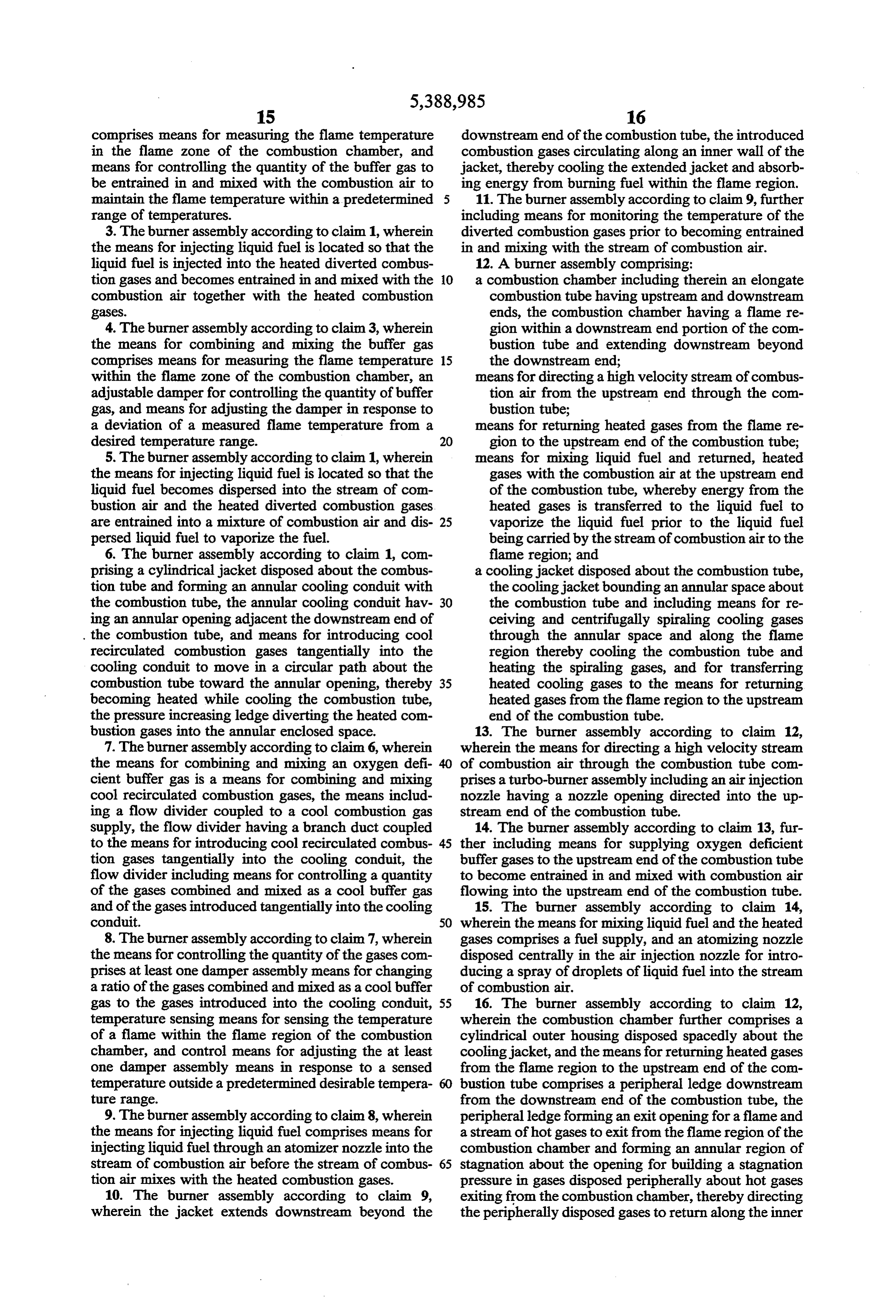
Page 14
wall of the housing toward the upstream end of the heated returned cooling gas to vaporize the fuel combustion tube. while mixing the fuel with the cooling gas and the 17. The burner assembly according to claim 16, stream of combustion air within the combustion wherein the means for mixing liquid fuel comprises at tube;
least one fuel injection nozzle disposed in the outer 5 mixing a controlled quantity of a buffer gas at the housing adjacent the upstream end of the combustion upstream end of the combustion tube with the re tube. turned heated cooling gas, the fuel and the stream 18. A method of generating a stream of hot combus of combustion air;
tion gases comprising: monitoring the flame temperature of the burning directing a stream of combustion air into a combus- 10 mixture; and tion chamber and into an upstream end of a com adjusting the quantity of the buffer gas to maintain bustion tube disposed in the combustion chamber the flame temperature within a range of desirable to move toward a flame region at a downstream temperatures.
end of the combustion tube within the combustion 19. The method according to claim 18, wherein mov chamber; 15 ing oxygen deficient cooling gas peripherally in a spiral injecting liquid fuel adjacent the upstream end of the ling motion about the combustion tube and peripherally combustion tube into the combustion chamber, along the flame region comprises: mixing the injected fuel into the stream of combus moving oxygen deficient cooling gas peripherally in a tion air and burning the fuel with the combustion spiralling motion through an annular enclosed air in the flame region of the combustion chamber; 20 space between the combustion tube and an encas moving oxygen deficient cooling gas peripherally in a ing cylindrical jacket from adjacent the upstream spiralling motion about the combustion tube and end of the combustion tube toward an annular peripherally along the flame region, thereby heat opening between the jacket and the combustion ing the cooling gas with heatenergy from the com tube at the downstream end of the combustion tube bustion tube and from burning fuel in the flame 25 and along an inner surface of an extension of the region; jacket past the downstream end of the combustion returning heated cooling gas to the upstream end of tube along the flame region. the combustion tube, mixing the fuel with the
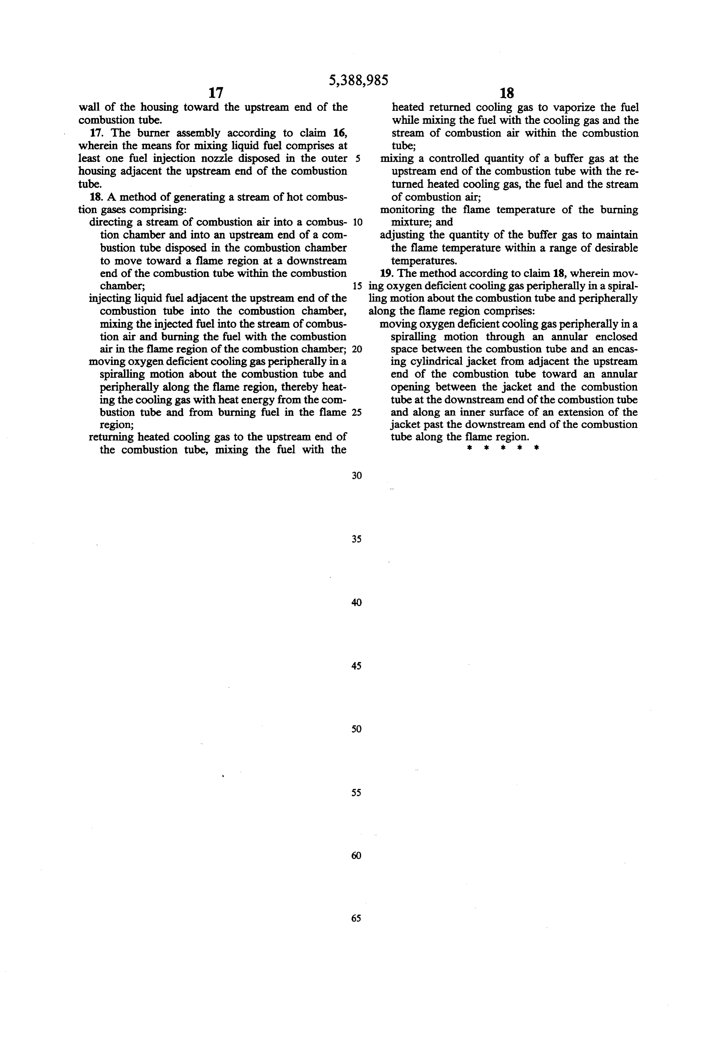
Page 15
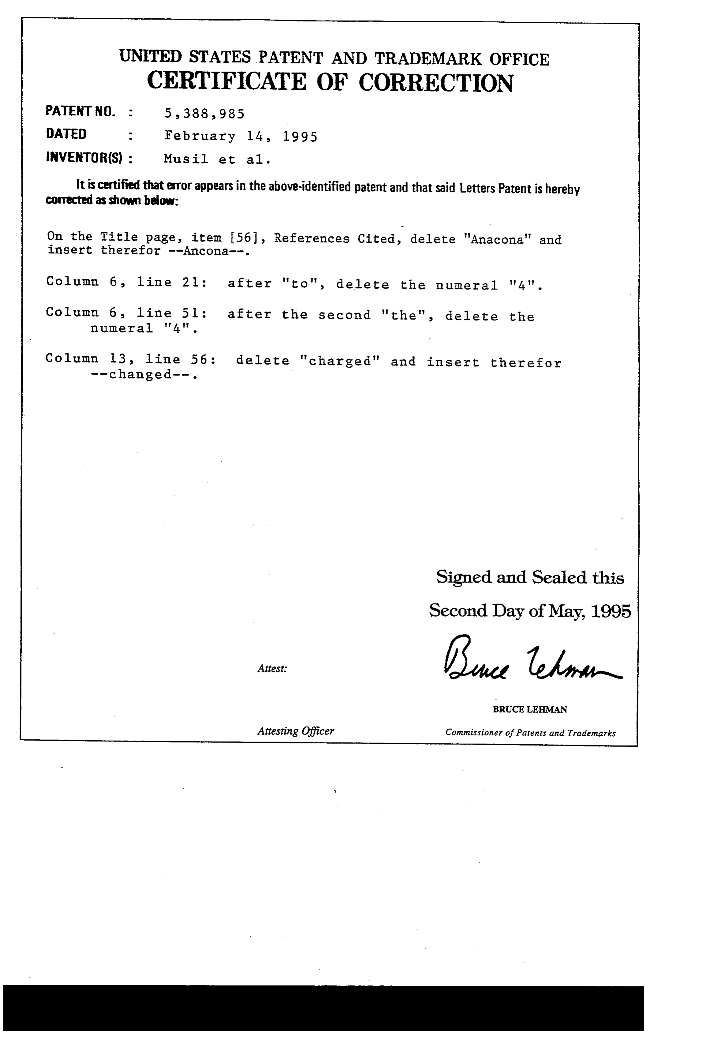
UNITED STATES PATENT AND TRADEMARK OFFICE
CERTIFICATE OF CORRECTION
INVENTOR(S) : Musil et al.
it is certified that error appears in the above-identified patent and that said Letters Patent is hereby corrected as shown below:
On the Title page, item 56), References Cited, delete 'Anacona' and insert therefor --Ancona--.
Column 6 line 21 : after "to", delete the numeral '4'. Column 6, 1ine 51 : after the second "the", delete the numeral '4'.
Column 13, line 56 : delete "charged" and insert there for
Signed and Sealed this
Second Day of May, 1995
BRUCE LEHMAN
Attesting Officer Commissioner of Patents and Trademarks
Provenance
- Collection
- Cited prior art
- Original PDF
- patentimages.storage.googleapis.com →
- Filed
- 1992-12-22
- Pages
- 15
- Method
- pdftotext (the PDF's own text layer) + pdftoppm 300dpi page scans
- Source
- Google Patents bibliographic record
- Granted
- 1995-02-14
- Inventors
- Joseph E. Musil; Lawrence G. Clawson; Cedarapids Inc
- Transcribed from
- patentimages.storage.googleapis.com →