patent · US2857961
Oil burners
28 October 1958
Page 1
Drawing sheet — no readable text.
Page 2
United States Patent Office 2,857,961 Patented Oct. 28, 1958
a spray nozzle 24 which has a number of small open ings in its forward end 25 and is arranged to discharge 2,857,961 finely divided fuel preferably in a narrow cone, as indi
OIL BURNERS
cated by the broken lines in Figure 1; however, the shape of the cone is not critical, inasmuch as the oil particles
are carried to the combustion zone by the air stream.
John W. Brown III, Lakewood, and Arvid C. K. Nihlen, Air
Oberlin, Ohio, assignors to Brown Fintube Company, to the mixing chamber 15 is supplied by a conduit 26 Elyria, Ohio, a corporation of Ohio that extends through the wall of the rear housing member 10 as shown.
Application July 13, 1954, Serial No. 443,026 10 The forward wall of the mixing chamber 15 is de 1 Claim. (CI. 158-76) fined by a conical member 30 which is welded to the forward end of the housing member 10 and converges in the direction of discharge of fuel and air from the mixing chamber. The small end of conical member 30
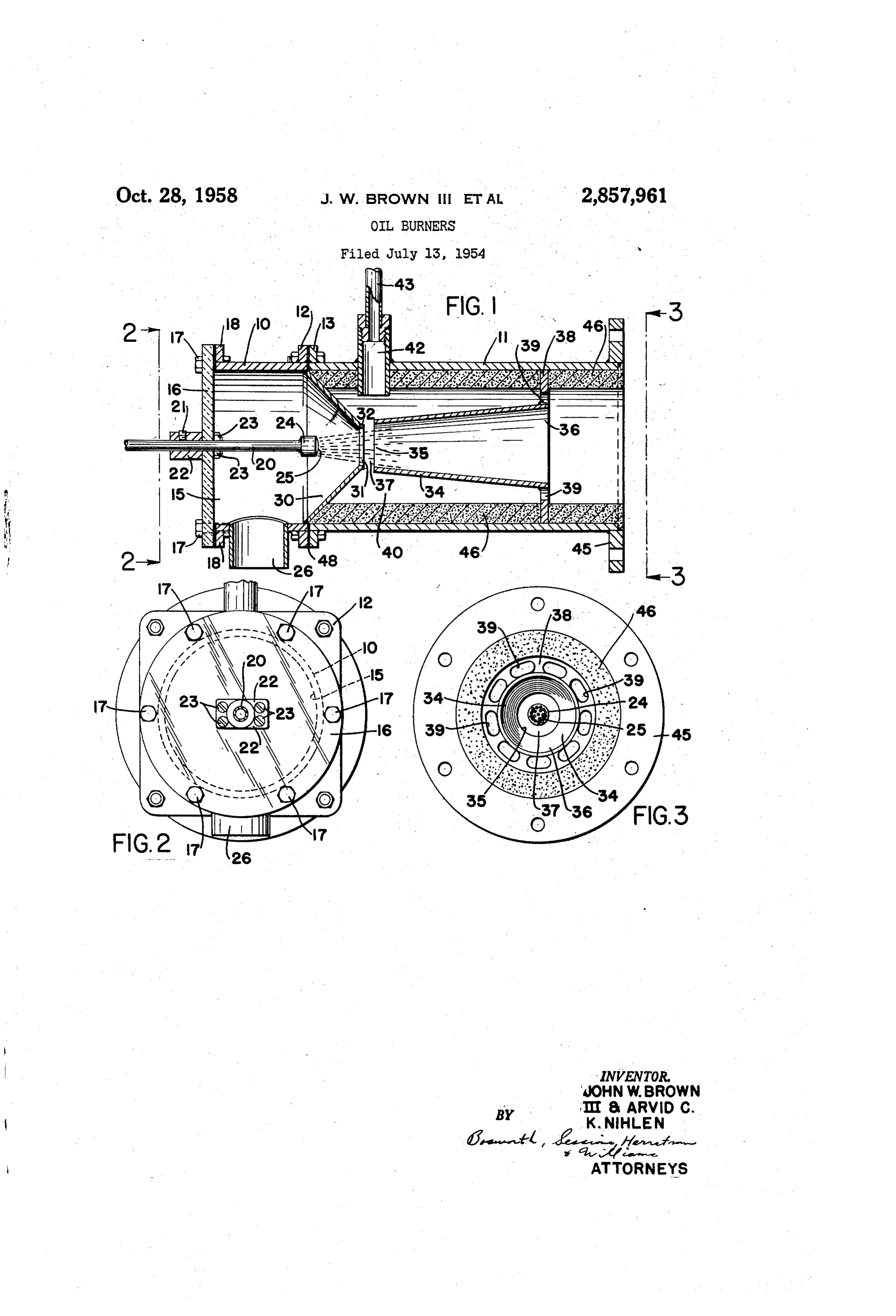
This invention relates to fuel burners and more par 5 terminates in an aperture 31 which is concentric with ticularly to high capacity burners adapted especially for the housing and with the axis of the nozzle 24. Pref liquid fuels, although they may also be used for burning erably, the opening 31 is surrounded by a short cylin gaseous fuels. - drical lip or flange 32. This lip is preferably machined A general object of the present invention is the pro accurately to insure even distribution of the fuel and vision of a compact, efficient burner adapted to produce 20 gases in the combustion zone. - a high temperature flame, with efficient combustion and Conical member 30 constitutes the first come of a large thermal output in relation to the size of the burner. venturi which is completed by a second conical member Another object of the invention is the provision of such 34. Conical member 34 diverges in the direction of flow a burner which can readily be adapted to different pur of gases in the burner; i. e., member 34 flares outwardly poses and uses. A further object is the provision of such 25 from the small opening 35 to the opening 36 at its dis a burner which can be started easily without the pro charge end. It will be noted that the opening 35 is duction of Smoke or soot and which can be operated slightly larger in diameter than the opening 31 of the with a clean flame and efficient combustion from its full converging conical member 30 and that the adjacent ends rated capacity down to approximately 10% of its rated of the two members are axially spaced apart to provide capacity. Another object is to provide a burner which 30 an open throat 37 as shown.
can produce a reducing flame while still maintaining clean The enlarged front end of the conical member 34 is combustion. Another object is the provision of burners supported from the forward housing member 11 by a of this character than can be manufactured economically perforated ring or spider 38 which acts as a flame holder and which are of sturdy and dependable construction. A and which is provided with a series of openings 39, as further object is the provision of burners which can be 35 indicated particularly in Figures 1 and 3. Conical mem converted from liquid to gaseous fuel with a minimum of ber 34 preferably terminates short of the discharge end difficulty. Another object is the provision of burners in of chamber 40 in the front housing member 11, as shown. which the combustion process and the walls of the com With this arrangement, the flow of gases at high velocity bustion chamber can be observed through a transparent through the venturi throat 37 defined by the small ends wall of the burner. 40 31 and 35 of the converging cone 30 and the diverging More specific objects of the invention are the provision cone 34 causes a reduction in pressure in the throat 37 of burners especially adapted for use in regenerative with the result that hot products of combustion are drawn furnaces, such as furnaces of the type utilized in the from the flame, which is held at the front end of cone melting of glass and the provision of furnaces embodying 34 by the spider 38. The hot products of combustion Such burners. Other objects and advantages of the in 45 are drawn rearwardly along the outside of cone 34 and vention will become apparent from the following descrip into the venturi throat 37 and are recirculated through tion of preferred forms thereof, reference being made : the combustion zone. The recirculated gas contains a to the accompanying drawings in which: substantial percentage of carbon monoxide inasmuch as Figure 1 is a longitudinal section through a preferred combustion is not complete adjacent the spider. With form of liquid fuel burner embodying the invention. 50 this arrangement, cone 34 is maintained at a red heat Figure 2 is a rear elevation of the burner shown in after the burner has been in operation for a short time Figure 1, the view being taken as indicated by line 2-2 and the fuel is heated and partially volatilized as it passes of Figure 1. through the cone. The result is a substantial increase Figure 3 is a front elevation of the burner shown in in the rate of combustion as compared to combustion Figure 1, the view being taken as indicated by line 55 in conventional burners; the fuel can be burned substan 3-3 of Figure 1. tially completely or a reducing flame can be produced by Referring now to Figures 1, 2 and 3 of the drawings, cutting down the supply of air; in either event the flame one preferred form of the invention comprises a cylin is clean and smokeless and there are substantially no de drical housing made up of a rear portion 10 and a front posits of carbon. In a successful burner embodying the portion 11, these portions having matching flanges 12 60 invention having the general configuration shown in Fig and 13 that are bolted together as shown. The rear ure 1, the total length of the housing is about 16 inches portion of the housing 10 constitutes an inlet or mixing and the outside diameter of the housing is about 6 inches. chamber 15, the rear end of which is closed by a panel The included angle of cone 30 in this burner is approxi or plate 16 that is preferably composed of glass or a mately 90° and the diameter of cone 30 at the throat suitable transparent plastic material. Plate 16 is secured 65 is about 1% inches. The small diameter of cone 34 is to the housing member 10 by bolts 17 extending through about 1% inches and the cone is about 7 inches long the plate and through the rear flange 18 of the housing and 3 inches in diameter at its large end. With this member. A supply pipe 20 for liquid fuel extends through arrangement the velocity of the gases through member an opening in plate 6 and is held in desired position 34 is approximately constant; i. e., the gases expand at of adjustment by set screw 21 mounted in block 22, 70 about the same rate that the cross section of member which is secured to plate 16 by appropriate screws 23, 34 increases. Preferably, the gas velocity at the discharge as indicated in Figure 2. Fuel conduit 20 terminates in end of member 34 is from 270 to 350 feet per second
Page 3
and about 10% of the gases are recirculated, passing on the rear member 10 while come 34 is supported on over the exterior of member 34 and in through the throat the front housing member 11, changing the thickness of 37 of the venturi. This burner operates with an output the gasket or gaskets 48 changes the spacing between of more than two million B. t. u. per hour and flame the cones. Once the parts have been adjusted properly temperatures" as high as 3000 F. The flame tempera for a particular flame temperature, further adjustment is ture can be varied by changing the gap 37 between cones seldom necessary.
30 and 34. Within reasonable limits, increasing the From the foregoing description of a preferred form gap increases recirculation of gases and increases the of the invention, it will be seen that the invention pro flame temperature, while reducing the gap reduces re vides a compact and efficient oil burner by means of circulation and reduces the flame temperature. O which high thermal output, and high temperatures can Inasmuch as the fuel nozzle is disposed well in back be obtained in small spaces. Burners embodying the of the venturi throat in the preferred form of the inven invention give clean and efficient combustion and operate tion, it is desirable to provide auxiliary means to make for long periods of time without requiring attention. it possible to light the burner easily and also to make The burners can be operated at as low as 10% of their it possible to operate the burner through a wide range 5 rated capacity while maintaining efficient operation and of capacity. In the form of the invention shown in smoke free and soot free combustion. The burners are Figure 1 this is accomplished by means of an auxiliary simple and sturdy and can be manufactured at reason gas burner 42 which extends through the wall of the able cost. The burners are particularly adapted to use housing member 11 and which may be supplied with gas in regenerative furnaces or wherever preheated air is from a conduit. 43. The gas discharged from burner 42 20 available.
may be ignited by means of any conventional spark Various changes and modifications in the preferred igniter (not shown) and gas burner 42 is directed toward forms of the invention may be made without departing the throat of the venturi provided by cones 30 and 34. (from the spirit and scope thereof. It is, therefore, to be The burner preheats the cones 30 and 34 and the hot understood that the forms of the invention described in products of combustion from the burner flow out through 25 detail herein are given by way of example and that the the cone 34. After the auxiliary burner 42 has been scope of the invention is defined by the appended claim. in operation for a few minutes, air may be supplied to We claim:
the main burner through conduit 26 and liquid fuel may A burner for fluid fuels comprising a housing having be supplied to the nozzle 24. The spray of liquid fuel "a rear portion defining - a mixing chamber, means for ignites immediately and clean and complete combustion 30 supplying air to the mixing chamber, a fuel conduit ex begins at once. With this arrangement the heating effect tending into the mixing chamber and terminating in a of the gas burner is such that clean, complete and effi fuel nozzle, a converging conical member defining the cient combustion of the liquid fuel can be obtained at forward, discharge end of the mixing chamber, said rates as low as 10% of the maximum output of the conical member having a forward axial opening and said burner. When the burner is being used at its maximum 35 fuel nozzle having a fuel discharge opening disposed to output it is not necessary to supply fuel to the gas burner the rear of said axial opening, a diverging conical mem 42 but improved results and greater flexibility of opera ber. having an opening near but axially spaced from the tion are obtained if the gas burner 42 is ignited when opening in said converging conical member, said two the main burner is operating at below 50% of rated conical members defining a venturi with an open throat, capacity. 40 means for supporting said diverging conical member In order to provide for support for the entire burner within said housing, said supporting means providing pas a flange 45 is secured to the forward end of the front sageways for the recirculation of combustion gases within housing member 11. This flange provides for mounting said housing from the discharge end of said diverging the burner on the heat. exchanger or other device with conical member around the exterior thereof and into : which it is to be used. Mounting on the front end only 45 the interior thereof through said open throat, and means eliminates problems due to expansion and contraction comprising an auxiliary gas burner adjacent said open of the burner under heat. The interior of the forward throat for preheating said diverging conical member. housing member 11 is lined with refractory insulating material 46 to keep the exterior of the burner cool and References Cited in the file of this patent prevent loss of heat from the recirculated gases. 50
UNITED STATES PATENTS
The apparatus can be adjusted for optimum results by sliding conduit 20 within block 22 to adjust the position 1,671,448 Plassmann ------------- May 29, f928 of the fuel nozzle with respect to the throat of the 1,699,732 Balmat --------------- Jan. 22, 1929 venturi, and the length of the venturi throat can be ad 1,729,763 De Florez ------------- Oct. 1, 1929 justed by inserting gaskets 48 of the proper thickness be 1,737,681 Plassmann ------------- Dec. 3, 1929 tween the flanges 12 and 13. Since cone 30 is supported 2,701,608 Johnson --------------- Feb. 8, 1955
Provenance
- Collection
- Cited prior art
- Original PDF
- patentimages.storage.googleapis.com →
- Filed
- 1954-07-13
- Pages
- 3
- Method
- pdftotext (the PDF's own text layer) + pdftoppm 300dpi page scans
- Source
- Google Patents bibliographic record
- Granted
- 1958-10-28
- Inventors
- Iii John W Brown; Arvid C K Nihlen; Brown Fintube Co
- Transcribed from
- patentimages.storage.googleapis.com →