patent · US3563055
Refrrigerant distribvtor
16 February 1971
Page 1
Drawing sheet — no readable text.
Page 2
United States Patent Office Patented Feb. 16, 1971
valve and remix it so that equal portions of gas and
REFRIGERANT DESTRIBUTOR liquid enter each circuit leaving the refrigerant distribu Alan Owens, Ballwin, Mo., assignor to Sporian Valve tor. When such a nozzle handles the normal refrigerant Company, St. Louis, Mo., a corporation of Missouri flow from the expansion valve, the pressure drop on a Filed Mar. 17, 1969, Ser. No. 807,668 refrigerant 22 system normally runs about 35 p.s. i. If an int. C. F.25b 39/02 attempt is made to introduce hot gas between the ex U.S. C. 62- 525 10 Claims pansion valve and such a refrigerant distributor, the pres Sure drop in the refrigerant distributor nozzle becomes excessive and will not allow sufficient hot gas or liquid
ABSTRACT OF THE DISCLOSURE O from the expansion valve to enter the evaporator. A refrigerant distributor for delivering refrigerant from A conventional refrigerant distributor utilized in the industry an expansion valve to a multi-circuit evaporator, the dis This heretofore to overcome this problem is shown in FIG. 2. tributor having a nozzle in a body chamber through which in which the nozzle conventional refrigerant distributor is one the liquid/gas mixture leaving the expansion valve is fed verging feed passageshasof been displaced from the con the refrigerant distributor to from a first inlet in one body end to a plurality of diver provide an internal chamber. Hot gas is then introduced gent feed passages in the opposite body end. The nozzle into this chamber between the nozzle and the feed pas includes a tube that extends forwardly in the chamber to sages so that the hot gas can be admitted to the evaporator a point of distribution in the chamber. A second inlet inlet downstream of the refrigerant distributor nozzle, in the body side communicates with the chamber in front of the nozzle partition yet rearwardly of the tube end 20 thereby preventing excessive pressure drop. The problem that occurs when this type of refrigerant so that hot refrigerant gas is mixed in the chamber around distributor is used is that the velocity of the hot gas enter the tube and then fed into the feed passages at the dis ing the side of the distributor tends to divert the flow tribution point. of liquid refrigerant coming through the nozzle and to An adaptor body portion that is compatible with a force it over to one side of the chamber so that the conventional distributor can be inserted between the ex majority of the liquid enters the feed passages opposite pansion valve and such distributor. The nozzle of the the hot gas inlet, while the hot gas enters the feed pas conventional distributor is removed and inserted in the body adaptor portion to cooperate with a nozzle tube in sages adjacent to the hot gas inlet. This unequal dis tribution of refrigerant to the evaporator causes varia the adaptor body portion, whereby the refrigerant from tion the expansion valve is delivered directly to the feed pas comesin especially 30 air temperature leaving the evaporator and be troublesome on multi-zone units where sages at the distribution point in the discharge portion of the conventional distributor. A web, carried by the the top half of the evaporator might be feeding one zone adaptor body portion, supports the tube. The hot gas inlet while the bottom half feeds another zone. in the adaptor body portion is located between the in stalled in theproblem
Another exists in refrigeration systems in field or on evaporators fitted with standard sertable nozzle and the web, the web being provided refrigerant distributors prior to the time that it is de with openings that permit flow along the tube to the feed cided that a hot gas bypass will be required. Because it passages at the distribution point. is quite a job to change a refrigerant distributor of the standard variety in which there is no facility for hot gas
BACKGROUND OF THE INVENTION 40 bypass to the type described above, some means is de sired for utilizing the standard refrigerant distributor and
This invention relates generally to improvements in introducing hot gas between the expansion valve and refrigerant distributors, and more particularly to means such a standard distributor.
for introducing hot gas to the evaporator inlet of a re SUMMARY OF THE INVENTION frigeration system for capacity reduction when a refriger ant distributor is used. The present refrigerant distributor includes a nozzle The practice of introducing hot discharge gas into the having a tube extending forwardly in the chamber from low side of a refrigeration system for capacity reduction the nozzle partition to substantially the point of distribu is well known. This is a method of capacity control to tion at the conical deflector provided between the di prevent the suction pressure from dropping below a de vergent feed passages for directing flow from the nozzle sired minimum. to the feed passages. A hot gas connection communicates When the hot gas is introduced into the low side down with the chamber in front of the nozzle partition yet rear stream of the evaporator, several problems occur. One wardly of the tube end. This extended nozzle tube allows problem is that the hot gas must be desuperheated, usually the liquid refrigerant from the expansion valve to travel by introducing liquid refrigerant from an auxiliary ex 55 to the point of distribution without being influenced by pansion valve prior to the time it enters the compressor. the velocity of the hot gas entering the side connection. Another problem is that the reduced load in the evap The hot gas enters the side connection and flows into orator allows the refrigerant gas velocity to become low the chamber in the annular area around the nozzle tube, and the oil return from the evaporator does not occur the hot gas mixing with the refrigerant from the nozzle properly. For these reasons, it is advantageous to intro 60 tube at the point of distribution and is delivered directly duce the hot gas to the inlet side of the evaporator So to the feed passages. This improved refrigerant distributor that the main expansion valve can accomplish the de allows equal distribution of the refrigerant to all circuits superheating, and the hot gas travel through the evap when hot gas is being bypassed to the evaporator and in orator keeps the velocity in the evaporator high so that no way interferes with the normal function of the re oil return is accomplished. 65 frigerant distributor during periods of high load, then When the evaporator is a multi-circuit evaporator, a there is no hot gas being bypassed.
refrigerant distributor must be used. The introduction of In another embodiment, a hot gas bypass adaptor body hot gas to the evaporator inlet presents a special prob is inserted between the refrigerant valve and the standard lem. The most common type of refrigerant distributor em refrigerant distributor, the adaptor portion allowing the ploys a nozzle and is commonly referred to as the pres 70 introduction of hot gas at this point without excessive sure drop type. The purpose of this nozzle is to receive pressure drop. To utilize this improved embodiment, the the refrigerant liquid/gas mixture leaving the expansion nozzle is removed from the standard distributor and
Page 3
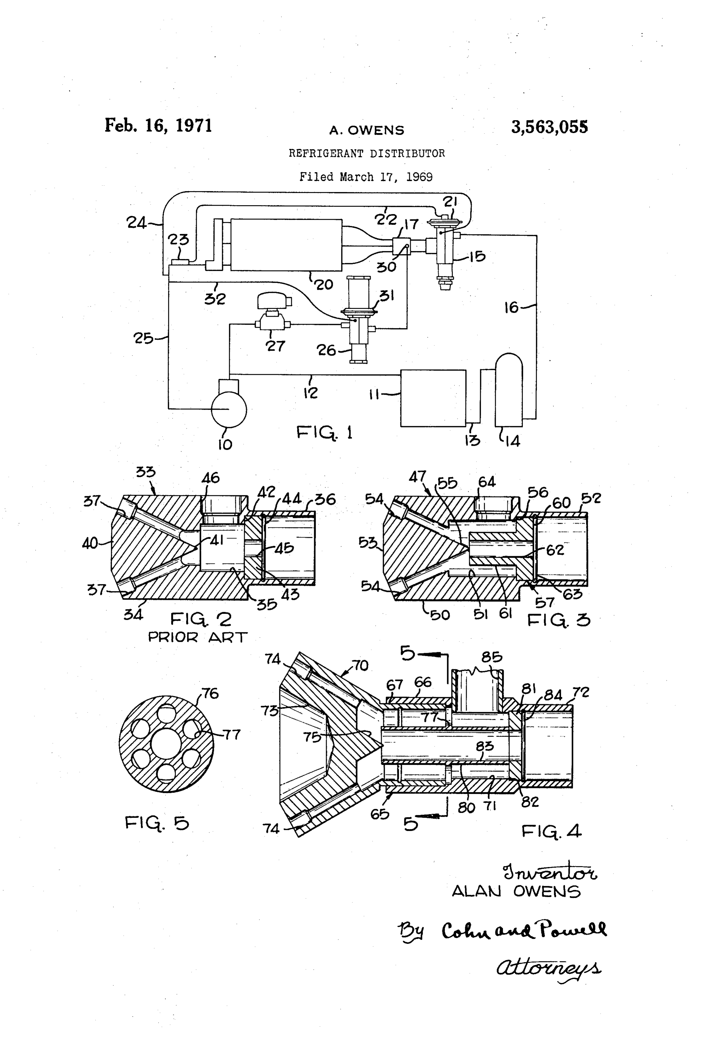
placed upstream of the bypass connection in the hot gas frigerant distributor. The underside of the diaphragm adaptor portion. Then, the expansion valve is connected constituting the motor element 31 of the discharge bypass to the inlet of this hot gas adaptor portion. The flow of valve 26 is subjected to pressure existing in the Suction liquid refrigerant from the expansion valve is then chan line 25 through the external tube 32. neled through the nozzle partition and nozzle tube to the FIG. 2 illustrates a prior art refrigerant distributor 33, point of divergence of the feed passages in the discharge the structure and function of which will be described in portion of the distributor. The hot gas enters the side order to clearly understand the structural differences and connection is the adaptor portion and then flows in the functional advantages of the improved refrigerant dis annular area of the chamber about the nozzle tube. The tributors constituting this invention. This prior art dis hot gas then passes through the openings in the Web that O tributor 33 includes a body 34 having an internal chamber supports the nozzle tube in the adaptor portion and passes 35. An inlet 36 in one end of the body 34 communicates through the annular area of the chamber around the noz with the chamber 35. The body 34 is provided with a plu zle tube. This hot gas joins the flow of refrigerant from rality of feed passages 37 extending divergently outward the nozzle tube at the point of divergence of the feed pas through the opposite body end 40 and communicating sages and thereby combines equally with the refrigerant 5 with the chamber 35. The formation of the divergent feed from the expansion valve. The adaptor portion enables the passages 37 form a substantially conical deflector 41 be use of the standard refrigerant distributor. tween the feed passages for directing flow into the feed While the above mentioned embodiments are utilized passages 37.
to introduce hot gas for capacity control, it will be un The body 34 is provided with an annular shoulder 42 derstood that the same devices can be utilized in re 20 between the inlet 36 and chamber 35. A nozzle 43, con verse cycle refrigeration systems to improve distributor stituting a partition, seats against the annular shoulder performance whenever the system is operated in the con 42 and is retained in place by a lock ring 44. The nozzle ventional manner and to allow reverse flow of liquid re partition 43 is provided with a port 45 aligned axially with frigerant out of the evaporator when it is being used as the conical deflector 4, the port 45 constituting a part of a condenser. 25 the inlet to chamber 35. Another inlet 46 is provided in It will also be understood that the present refrigerant the side of distributor body 34 and communicates with distributors may be utilized in refrigeration systems em the chamber 35 between the nozzle partition 43 and the ploying hot gas defrost in which it is desirable to drain conical deflector 4.
liquid out of the evaporator during the defrost cycle In using this prior art distributor 33, the refrigerant through the refrigerant distributor. The present embodi 30 liquid/gas mixture leaving the expansion valve 5 flows ments would allow this function to be accomplished with a through the inlet 36 and the nozzle port 45 into the standard refrigerant distributor when the adaptor portion chamber 35. The hot gas from the hot gas bypass is in is used or it could be accomplished with the use of the troduced into chamber 35 through the side inlet 46 be present distributor in which the advantage would be bet tween the nozzle partition 43 and the feed passages 37. ter refrigerant distribution because the refrigerant from 35 With this type of refrigerant distributor, the velocity of the expansion valve is conveyed closer to the point of the hot gas entering the side inlet 46 tends to divert the divergence before expansion takes place. flow of liquid refrigerant leaving the nozzle port 45 and BRIEF DESCRIPTION OF THE DRAWING tends to force it over to one side of the chamber 35 so that the majority of the refrigerant liquid enters the feed
FIG. 1 is a diagrammatic view of the system in which 40 passages 37 opposite the hot gas inlet 46, while hot gas the refrigerant distributor is used; enters the feed passages 37 adjacent to the hot gas inlet FIG. 2 is a longitudinal cross section of the heretofore 46. This unequal distribution of refrigerant to the evapo conventional refrigerant distributor designated as prior rator 20 causes variations in air temperature leaving the art; evaporator 20 and becomes especially troublesome on FIG. 3 is a longitudinal cross section of one embodi 45 multi-zone units where the top half of the evaporator 20 ment; might be feeding one zone and the bottom half feeding FIG. 4 is a longitudinal cross section of another em another zone.
bodiment, and An improved refrigerant distributor which overcomes FIG. 5 is a cross section taken on line 5-5 of FIG. 4. the problems of the prior art distributor of FIG. 2, is DESCRIPTION OF THE PREFERRED 50 shown in FIG. 3. In this distributor 47, the distributor EMBODIMENT body 50 is provided with an internal chamber 51. One end The refrigeration system in which the refrigerant dis of body 50 is provided with an inlet 52 that communicates tributor is used is illustrated diagrammatically in FIG. 1. with chamber 51. The opposite end 53 of body 50 is pro In this System, a compressor i0 is connected to a condens 55 vided with a plurality of divergently extending feed pas er 11 by line 12, the outlet of the condenser 11 being Sages 54, the feed passages 54 extending outwardly from Substantially a point of distribution in chamber 51. A sub connected by line 3 to a receiver 4. A thermostatic Stantially conical deflector 55 is provided between the eXpansion valve 15 is connected to the receiver 4 by divergent feed passages 54 for directing flow into the feed line 16, the outlet of the expansion valve 5 being con paSSages 54.
nected to a refrigerant distributor 17 that feeds refrig 60 An annular shoulder 56 is provided by the body be erant to a multi-circuit evaporator 20. The top of the tween the inlet 52 and chamber 51. Seated on the annular diaphragm constituting the motor element 21 of the ex shoulder 56 is a nozzle generally indicated by 57, the pansion valve 15 is connected by tubing 22 to a sensing nozzle 57 including a nozzle partition 60 extending across bulb 23 located at the outlet of evaporator 20. An ex the chamber 51 at the inlet 52 and a nozzle tube 6 ex ternal tube 24 connects the expansion valve 15 to the tending forwardly from the nozzle partition 60 in the evaporator downstream of the sensing bulb 23 to subject chamber 51 to the distribution point defined by conical the underside of the motor element 21 to the system pres deflector 55. The nozzle 57 is provided with a port 62 Sure at that Zone. The outlet of evaporator 20 is con axially aligned with the conical deflector 55 and adapted to nected to the compressor 10 by suction line 25.
In this system, a hot gas bypass is provided for feed 70 passagesrefrigerant deliver from the inlet 52 directly to the feed 54 around the conical deflector 55. The nozzle ing hot gas directly to the refrigerant distributor 17 from the compressor 10. This hot gas bypass includes a dis 57Formed is retained by lock ring 63.
in the side of distributor body 50 is a hot gas charge bypass valve 26 having its inlet connected to a hot inlet 64 that communicates with the chamber 51 forwardly gas Solenoid valve 27 to the compressor 10, and having of the nozzle partition 60 yet rearwardly of the front end its outlet connected to a side connection 30 of the re of nozzle tube 61. With this arrangement, the hot gaS
Page 4
from inlet 64 flows into the chamber 51 around the ex A hot gas inlet 85 is provided in the side of adaptor terior of nozzle tube 61 and flows forwardly so as to mix body portion 66 and communicates with the chamber 71 with the refrigerant delivered by the nozzle tube 61 at the forwardly of the nozzle partition 81, yet rearwardly of distribution point. The hot gas and the refrigerant liquid/ the front end of nozzle tube 80. Specifically, the hot gas gas mixture delivered by the nozzle tube 61 is mixed com inlet 85 is located rearwardly of the web 76. The hot gas pletely and fed equally by the conical deflector 52 directly from inlet 85 flows around the exterior of nozzle tube 80 into the feed passages 54. and flows forwardly through the web openings 77 to the In operation, when the suction pressure reaches a pre distribution point around the front end of tube 80, at determined minimum, the discharge bypass valve 26 will which point the hot gas is fed directly into the feed deliver hot gas from the compressor 10 directly to the O passages 74. The refrigerant flow through the nozzle refrigerant distributor 47 through the hot gas inlet 64. tube 80 is directed to the distribution point and flows The refrigerant liquid/gas mixture leaving the expansion around the conical deflector 75 and is directed into the valve 15 is fed into the inlet 52 and moves through the feed passages 74.
nozzle port 62, the nozzle tube 61 feeding the liquid/gas It will be understood that the discharge portion 70 and mixture directly to the distribution point at the conical the nozzle partition 81 constitute parts of the conven deflector 55 where the feed passages 54 diverge. This ex tional distributor. When it is decided that the hot gas tended nozzle tube allows the liquid refrigerant from the bypass is needed in the system, the discharge portion 70 expansion valve 15 to travel to the point of distribution of the conventional distributor is interfitted with the without being influenced by the velocity of the hot gas adaptor body 66 and the nozzle partition 81 is removed entering the inlet 64. The hot gas entering the inlet 64 20 from this conventional distributor and placed in the adap flows around the nozzle tube 61 and forwardly to the tube 72 tor body 66 in the manner shown in FIG. 4. The inlet end where the hot gas joins with refrigerant from the of the adaptor body portion 66 is connected to the nozzle 57 at the point of distribution. The conical deflec expansion valve 15, and the feed passages 74 are con tor 55 feeds the co-mingled refrigerant from the nozzle nected to the multi-circuit evaporator 20, while the hot tube 61 and the hot gas from the inlet 64 directly and gas inlet 85 is connected to the discharge bypass valve 26. equally to the feed passages 54. The operation and functional advantages of the distri Because the hot gas is admitted to the evaporator inlet butor shown in FIGS. 4, 5 are essentially identical to those previously described with respect to the distributor dis downstream of the refrigerant distributor nozzle 57, ex closed in FIG. 3. Basically, the refrigerant liquid/gas cessive pressure drop is prevented. Moreover, the hot gas being introduced into the evaporator 20 downstream 30 mixture from the expansion valve 15 is fed through the from the expansion valve 15 keeps the velocity in the nozzle port 83 and is delivered by the nozzle tube 80 evaporator 20 sufficiently high so that oil return is ac directly to the distribution point defined by the conical complished. The particular nozzle construction and its deflector 75. This refrigerant from the nozzle tube 80 arrangement with respect to the hot gas inlet 64 and the flows around the conical deflector 75 and is directed into the feed passages 74. The hot gas introduced through conical deflector 55 enables equal distribution of refriger 35 the ant to all circuits of the evaporator 20 when hot gas is hot gas inlet 85 flows into the chamber 71 and around being bypassed to the evaporator 20, and does not inter the exterior of nozzle tube 80. The hot gas flows axially fere with the normal function of the refrigerant distribu along the nozzle tube 80 through the web openings 77 tor during periods of high loads when there is no hot gas 40 and is delivered to the distribution point around the being bypassed. front end of nozzle tube 80, at which point the hot gas FIGS. 4 and 5 disclose a refrigerant distributor that is mixed with the refrigerant flow from the nozzle tube incorporates the parts of a standard refrigerant distribu 80 and is delivered in equal proportion to the feed pas tor and yet enables the use of a hot gas bypass. Some sages 74.
systems are installed in the field and are fitted with I claim as my invention:
standard refrigerant distributors prior to the time that if 1. A refrigerant distributor, comprising: is decided that a hot gas bypass will be required. The (a) a body having an internal chamber, distributor disclosed in FIGS. 4 and 5 enables the utiliza (b) the body being provided with a first inlet in one tion of the standard refrigerant and yet permits the in body end adapted to receive refrigerant from an troduction of hot gas. expansion valve and communicating with the cham In this embodiment, the distributor body referred to 50 (c)ber,the body being provided with a plurality of feed at 65 includes an adaptor body portion 66, one end of passages extending through the opposite body end which receives the inlet portion 67 of the conventional and communicating with the chamber, distributor 70. When so connected, the body 65 is pro (d) a nozzle fixed in the body and including a parti vided with an internal chamber 71. The adaptor body por tion and a tube having a port receiving flow from the tion 66 is provided with an inlet 72 that communicates 55 with the chamber 71. The opposite end of body 65, as first inlet, the tube extending forwardly in the cham provided by the discharge portion 73 of the conventional ber from the partition to deliver flow to the feed distributor 70, is provided with a plurality of outwardly passages, the chamber providing an annular space diverging feed passages 74 converging to a distribution around the tube rearwardly of the discharge end point in chamber 71. A conical deflector 75 is provided 60 (e)ofthe the tube, and body being provided with a second inlet in its on the discharge portion 73 between the divergent feed passages 74. side adapted to receive hot refrigerant gas or to Formed integrally with and carried by the adaptor body allow discharge of liquid refrigerant, the second in 66, is a web 76 extending across the chamber 71. The let being located in front of the nozzle partition yet web 76 is provided with a plurality of openings 77 located 65 rearwardly of the discharge end nozzle tube, and circumferentially in regularly spaced relation. A nozzle communicating directly with the annular space tube 80 is carried by and formed integrally with the around the tube.
web 76, the nozzle tube 80 being aligned axially with 2. A refrigerant distributor as defined in claim 1, in the conical deflector 75. A nozzle partition 81 seats on which:
an annular shoulder 82 formed between the adaptor 70 (f)tially the feed passages extend outwardly from substan a point of distribution in the chamber, body portion and the inlet 72, the nozzle partition engag ing one end of nozzle tube 80. The nozzle partition 81 (g) the nozzle tube extends forwardly to substantially and the nozzle tube 80 are provided with a port 83. A the point of distribution, and lock ring 84 secures the nozzle partition 81 in place across (h) the second inlet is located rearwardly of the dis the chamber 71. 75 tribution point.
Page 5
3. A refrigerant distributor as defined in claim 1, in discharge of liquid refrigerant, the second inlet com which: municating with the chamber in front of the nozzle (f) a substantially conical deflector is provided be partition yet rearwardly of the nozzle tube, tween the feed passages for directing fiow into the (f) the body including an adaptor portion in which the feed passages, and first inlet is provided at one end, and including a dis (g) the discharge end of the nozzle tube extends for 5 charge portion in which the feed passages are pro wardly substantially to the conical deflector to deliver vided, the discharge portion being selectively inter flow from the nozzle against the deflector. fitted in the other end of the adaptor portion, and 4. A refrigerant distributor as defined in claim 1, in (g) the nozzle tube extending forwardly in the cham which: O ber longitudinally of the adaptor portion and into the (f) the annular space around the tube extends at least discharge portion.
from the second inlet forwardly to the feed passages. 8. A refrigerant distributor as defined in claim 7, in 5. A refrigerant distributor as defined in claim 3, in which:
which: (h) a web is carried by the adaptor portion and sup (h) the nozzle tube has its longitudinal axis substan I5 ports the nozzle tube in the chamber with one tube tially aligned with the axis of the conical deflector end located adjacent the nozzle partition, and and communicates directly with the feed passages (i) the second inlet is located in the adaptor portion around the conical deflector, and between the nozzle partition and the web, the web (i) the annular space around the tube communicates being provided with openings for flow from the sec directly with the feed passages around the discharge 20 ond inlet to the feed passages. end of the nozzle tube. 9. A refrigerant distributor as defined in claim 8, in 6. A refrigerant distributor as defined in claim 1, in which:
which: (j) a substantially conical deflector is provided between (f) a substantially conical deflector is provided between the divergent feed passages for directing flow into the the feed passages for directing flow into the feed 25 feed passages, - passages, (k) the web supports the nozzle tube intermediate the (g) the discharge end of the nozzle tube extends for tube ends, and wardly substantially to the conical deflector to deliver (1) the other tube end is located adjacent to the conical flow from the nozzle against the deflector, deflector to deliver flow from the tube against the (h) the annular space around the tube extends at least 30 deflector.
from the second inlet forwardly to the feed passages, 10. A refrigerant distributor as defined in claim 9, in (i) the nozzle tube has its longitudinal axis substantially which:
aligned with the axis of the conical deflector, (m) the chamber extends completely around the (j) the discharge end of the nozzle tube communicates periphery of the nozzle tube and extends at least directly with the feed passages around the conical de 35 from the second inlet forwardly to the feed passages, flector, and (n) the nozzle tube has its longitudinal axis substan (k) the annular space around the tube communicates tially aligned with the axis of the conical deflector, directly with the feed passages around the discharge (o) the nozzle tube communicates directly with the end of the nozzle tube. feed passages around the conical deflector, and 7. A refrigerant distributor, comprising: 40 (p) the chamber communicates directly with the feed (a) a body having an internal chamber, passages around the nozzle tube. (b) the body being provided with a first inlet in one body end adapted to receive refrigerant from an ex References Cited pansion valve and communicating with the chamber, UNITED STATES PATENTS (c) the body being provided with a plurality of feed 45 3,110,162 11/1963 Gerteis -------------- 62-196 passages extending through the opposite body end and communicating with the chamber, 3,120,743 2/1964 Wilson -------------- 62-525 (d) a nozzle including a partition and a tube having a MEYER PERLIN, Primary Examiner port receiving flow from the first inlet, the tube ex tending forwardly in the chamber from the partition 50 U.S. C. X.R.
to deliver flow to the feed passages, 62-504; 137-602 (e) the body being provided with a second inlet in its side adapted to receive hot refrigerant gas or to allow
Provenance
- Collection
- Cited prior art
- Original PDF
- patentimages.storage.googleapis.com →
- Filed
- 1969-03-17
- Pages
- 5
- Method
- pdftotext (the PDF's own text layer) + pdftoppm 300dpi page scans
- Source
- Google Patents bibliographic record
- Granted
- 1971-02-16
- Inventors
- Alan Owens; Sporlan Valve Co
- Transcribed from
- patentimages.storage.googleapis.com →