patent · US20140360474A1
Method and system for providing fuel to internal combustion engines
11 December 2014
Page 1 — bibliographic record
(19) United States (12) Patent Application Publication (10) Pub. No.: US 2014/0360474 A1
GURIN et al. (43) Pub. Date: Dec. 11, 2014 (54) METHOD AND SYSTEM FOR PROVIDING Publication Classification
FUEL TO INTERNAL COMBUSTION
ENGINES (51) Int. Cl.
(71) Applicant: Helpful Technologies Inc., Fort F02M 37/00 (2006.01)
(72) Inventors: Victor GURIN, Rochester, NY (US); (2013.01); F02M 23/12 (2013.01) Igor GACHIK, Boca Raton, FL (US); USPC ............................ 123/525; 123/531:123/575 Serguei PERMIAKOV, Kanata (CA); (57) ABSTRACT
Roman PRESS, Pittsford, NY (US);
Leonid FAYNBERG, Davie, FL (US); The present invention relates to a system and method for Aleksandr RESHETNYAK, providing fuel to internal combustion engines including fuel Hollywood, FL (US) activation prior to injection. The method carried out by the system comprises dissolving a mixture of gasses providing improved fuel dispersing after fuel injection into a combus (21) Appl. No.: 14/457,034 tion chamber. Dissolved gasses desorption is stimulated from a unsaturated fuel solution. Full control of fuel flows with dissolved gas/gasses to and from injectors and FET technol (22) Filed: Aug. 11, 2014 ogy based on Henry's law (dissolving gasses in the liquids) and Kelvin principle (vapor pressure over droplet Surface).
The system consists of compact components, including
Related U.S. Application Data exhaust gasses recirculation system which can be easily added to existing diesel and gasoline engine fuel Supply sys (60) Division of application No. 13/920,508, filed on Jun. tems. The method and system were tested with four different 18, 2013, which is a continuation of application No. types of engines and provides fuel economy in 12-20% 12/798.513, filed on Apr. 6, 2010, now Pat. No. 8,464, decrease of emissions and up to 25% at variable engine loads 694. and significantly at engine cold start.
Page 2
Drawing sheet — no readable text.
Page 3
Drawing sheet — no readable text.
Page 4
Drawing sheet — no readable text.
Page 5
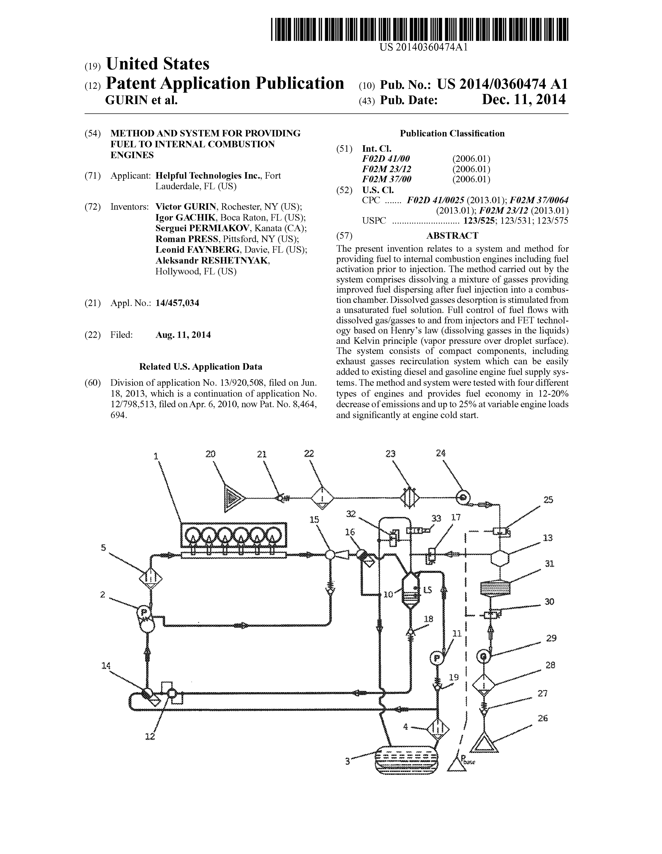
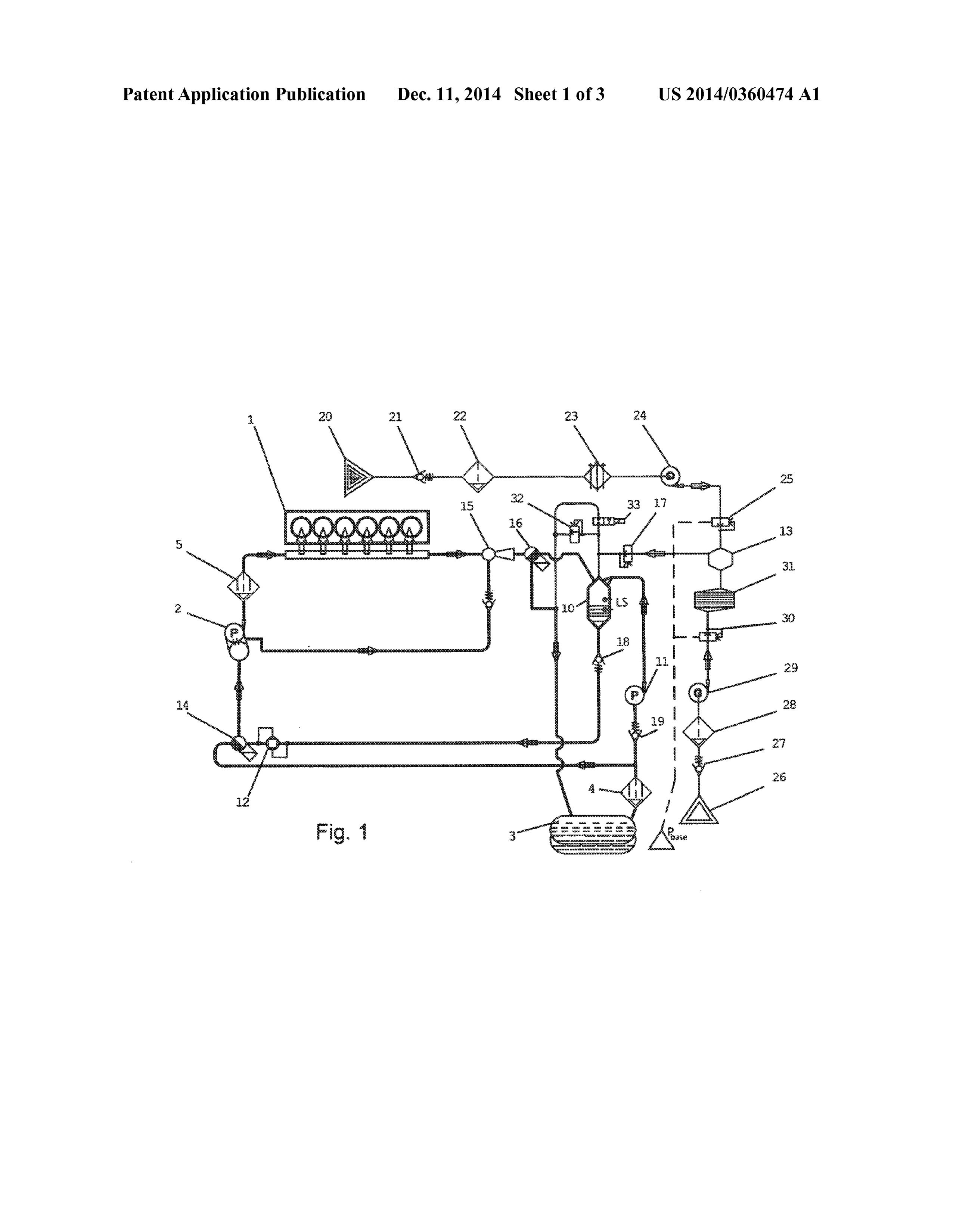
US 2014/0360474 A1 Dec. 11, 2014
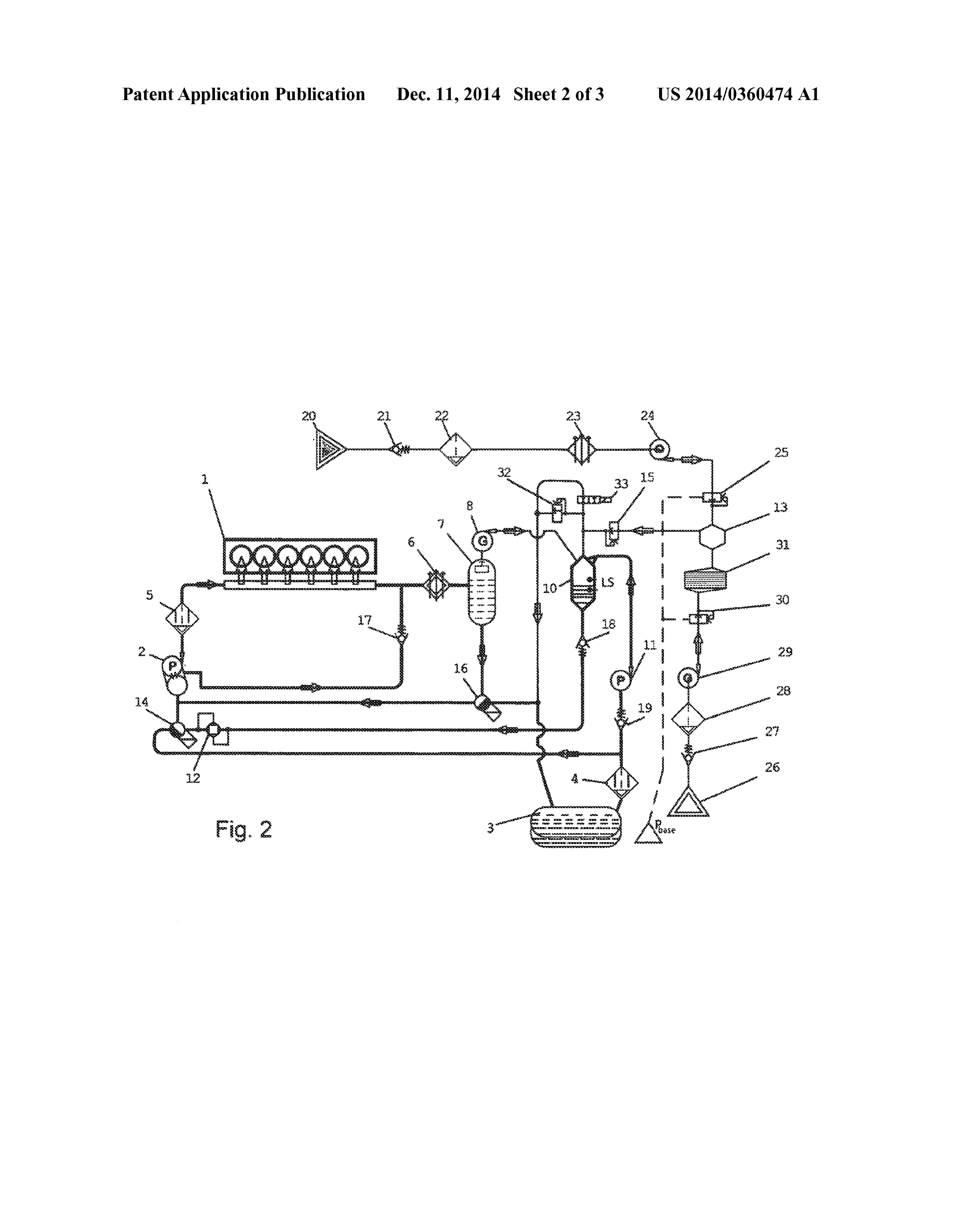
METHOD AND SYSTEM FOR PROVIDING 0007. In accordance with invention there are provided FUEL TO INTERNAL COMBUSTION technical solutions for different types of fuel systems. The ENGINES fuel is prepared for injection and combustion in a special device, an absorber, where the fuel is contacted with the gas or
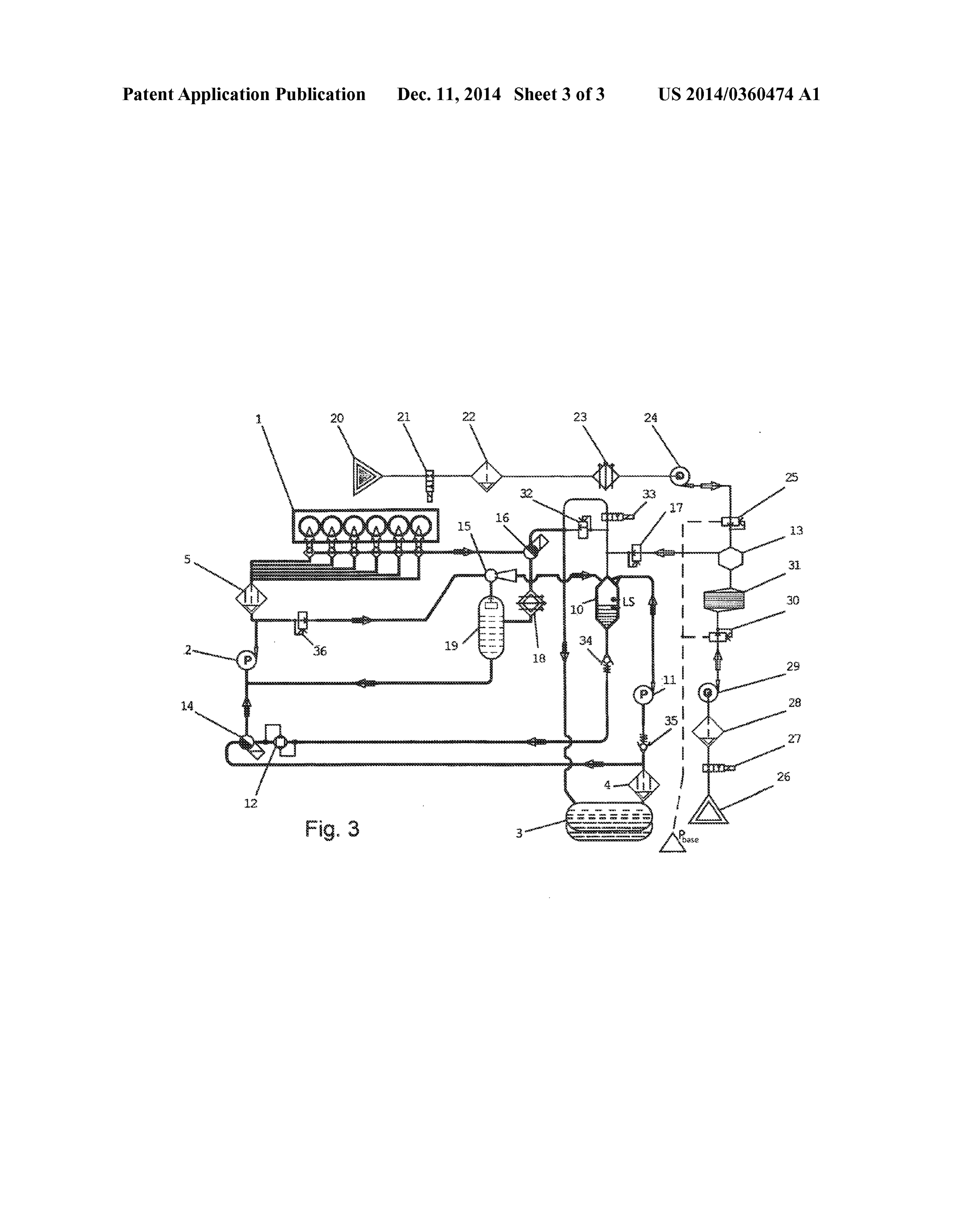
CROSS REFERENCE TO RELATED gasses. The gas pressure inside the absorber is maintained APPLICATIONS higher than the fuel pressure Supplied to the absorber; the gas 0001. The present application is a Divisional Application is dissolved in the liquid fuel forming an unsaturated fuel of Continuation application Ser. No. 13/920,508, filed Jun. Solution having no free gas phase. The resultant fuel Solution 18, 2013, which is a Continuation of application Ser. No. is guided to a main fuel pump that further increases the 12/798.513, filed Apr. 6, 2010, now U.S. Pat. No. 8,464,694, pressure of the fuel Solution providing no free gas phase. the entire disclosures of which are incorporated herein in their Upon injection in the combustion chamber in addition to the entireties. hydrodynamic fuel atomization a violent degassing takes place providing continuous chainbreaking of fuel microdrop
FIELD OF INVENTION letto fine “nano' sizes. The combination of the gas desorption from the fuel solution with the hydrodynamic breaking-up of 0002 The present invention relates to liquid fuel combus the injected fuel provides a fundamentally new process of the tion and, more particularly, to the preparation of liquid fuels fuel atomization in the combustion chamber. The fuel micro for combustion in a combustion chamber of internal combus droplets continuously break up to significantly Small sizes tion engines. providing an extremely high interfacial curvature and liquid
BACKGROUND OF THE INVENTION
vapor (fuel) pressure increases by as much as 8-10 times. This effect is described by the Kelvin equation and it is well known 0003. In existing internal combustion engines such as die that the quicker liquid fuel evaporates the more rapid and sel and gasoline engines, as well as other types of engines a effective the combustion of the gasoline or diesel is. One more fuel is injected into a combustion chamber at high pressure. A important additional effect of the new injection process: the charge of the fuel is injected by means of Solenoid injectors continuous chain breaking of the fuel droplets caused by the controlled by an on-board microcomputer and connected to a gas desorption prevents coalescence of the droplets and for common rail. The on-board microcomputer controls injection mation of a fuel film on the walls of the combustion chamber. timing and duration as well as an injection pressure by means As a result more fuel surface is available for contact with air. of a two-stage main fuel pump. To provide better fuel atomi Thus the fuel burns faster and more completely giving less Zation after injection into combustion chamber the fuel pres harmful emissions.
Sure in the common rail upstream of the injectors is main 0008 Taking into account this and other objects a method tained at high level, e.g., in diesel engines the fuel pressure is of fuel activation and Supplying into the combustion process maintained at 2000-2400 bars. is presented. The method comprises steps of 0004 Currently different approaches are used to improve 0009 a) Dissolving a gas/mix of gasses in fuel thereby the fuel atomization and dispersion in the combustion cham transferring the liquid fuel into a state of unsaturated “fuel/ ber after injection. For example, jointinjection of hydrogen or gas' solution without any free gas phase; the fuel is dispersed natural gas with gasoline is used, in other systems a com in the absorber to increase the contact Surface with the gas pressed air stream is directed to the fuel spray injected into the supplied to the absorber at high pressure of up to 100 bar; the combustion chamber. There is also an approach where fuel process is performed, preferably, at lower temperatures, and and air are induced with the same charge to reduce coales gas used for dissolution can be a mixture of for example, cence of the fuel microdroplets after the injection. exhaust gases and oxygen enriched air having O content of 0005. There are known attempts to disperse fuel by dis up to 35% and fuel/mixture of gases ratio by weight of 1:0. Solving some gas, e.g., air or carbon dioxide, in the liquid fuel 055. The purpose of using the mixture with increased oxygen and Subsequently injecting this solution into the combustion content is to increase the local concentration of the oxidant chamber. When injected into the combustion chamber the during gas desorption. The presence of locally available oxi dissolved gas is released from the Solution providing very fine dant helps more quicker fuel ignition. dispersion of the liquid fuel. In U.S. Pat. No. 6,273,072 0010 b) Activating “fuel/gas' solution by changing the (Knapstein et al.) and U.S. Pat. No. 701 1,048 (Gurinet al.), state of the “fuel/gas” solution for a short period of time to a there are described methods and devices for implementation boundary state of oversaturated Solution in Such way as to and utilization of the abovementioned effect. The described minimize or exclude free gas bubbles flashing out of the fuel systems require special devices that are Supposed to work solution flow at the inlet of the main fuel pump by lowing the within a certain range of parameters and at the same time pressure of the fuel solution flow or by ultrasound treatment certain conditions should be observed to provide the fuel/gas in a hermetic vessel comprising a vibrating element that by Solution to the combustion chamber in proper condition. In ultrafast oscillations forms partial pressure decrease of the practice it is difficult to satisfy both of these requirements fuel solution flowing through the vessel. simultaneously, and the achieved effect is not stable at various 0011 c) Merging the recirculation fuel solution flows loads. pumped out after the injection from common rail and main
SUMMARY OF THE INVENTION
fuel pump, cooling down the fuel solution to 50° C. and guiding it to the absorber to separate free gas/fuel vapor 0006 An object of this invention is to provide a method phase.
and apparatus which overcomes the abovementioned disad 0012 d) In the fuel system with single stage main fuel vantages and which provides for further improvement in the pump and distributed injection pumps the return flow is fuel injection into the combustion chamber that reduces fuel cooled, separated from free gas/fuel vapor phase and guided consumption as well as emissions. to the inlet of the main fuel pump. Some fuel after the main
Page 6
US 2014/0360474 A1 Dec. 11, 2014
fuel pump is guided to a nozzle of a jet pump which is used to 0025. The activation system according to the present pump out free gas/fuel vapor phase from a gas separator and invention consists of two Subsystems: a conditioning Sub the mix flow then is fed to the absorber to separated liquid and system and a gas preparation Subsystem. gas phases. This helps to avoid gas or vapor bubbles appear 0026. The conditioning subsystem comprises an absorber ing that may create pressure pulses at the outlet of the main 10, a feeding pump 11, a differential pressure regulator 12, a fuel pump and affect the operation of the fuel injectors. jet pump 15. Three-way valves 14 and 16 are used to change 0013 e) Preparing the gas mixture to be used for dissolu from standard (base) fuel Supply system to the conditioning tion in the fuel by cooling and compressing the exhaust gases subsystem and vice versa. Check valves 18, 19 prevent fuel to and mixing it with oxygen enriched air formed by filtering flow in wrong direction.
compressed air through a special membrane filter, prepared 0027. The gas preparation subsystem comprises a reactor gas mixture is guided to the absorber for dissolving in the 13 and two air and exhaust gases Supply lines. Air from air liquid fuel. source 26 flows through a filter 28, a compressor 29, a pres 0014 With this and other objects in view there is provided, Sure regulator 30, and an oxygen enrichment membrane filter in accordance with the invention, a system for liquid fuel 31, a check valve 27 prevents air to flow in wrong direction; activation and feeding activated liquid fuel to the combustion exhaust gases from exhaust line of the engine 20 flows chamber for combustion, comprising: through a filter 22, a cooler 23, a compressor 24 and a pressure 00.15 a) an absorber for fuel conditioning, having a liquid regulator 25, check valve 21 prevents exhaust gasses to flow inlet port for providing a fresh liquid fuel from a fuel tank, a in wrong direction.
gas inlet port for providing gas orgas mixture, an inlet port for 0028. The gas mixture is prepared in the reactor 13 by providing returned fuel flows from an engine common rail mixing the exhaust gases as sources of CO with oxygen and main fuel pump, and an outlet port for Supplying a fuel enriched air that is formed after ambient air passes through Solution from the absorber to an engine; the oxygen enrichment membrane filter 31. Mixing of two gas 0016 b) a fuel solution activator for momentary transfer streams in equal portions by weight is provided by pressure ring the fuel Solution to a state of oversaturated Solution regulators 25 and 30 having common control line. Required thereby preparing the fuel Solution to a burst gas desorption at pressure of the gas mixture is provided by compressors 24 and injection into the combustion chamber, 29 and controlled by the pressure regulators 25 and 30. 0017 c) a fuel supply subsystem for supplying the fresh (0029. The fuel from fuel tank 3 is delivered by feeding liquid fuel to the absorber with maintaining fuel level inside pump 11 to the nozzles mounted in the absorber 10. The the absorber between min and max limits; feeding pump 11 provides the fuel pressure P. The gas mix 0018 d) a subsystem for collecting returned flows from ture from the reactor 13 is guided to the gas inlet port of the the engine and main fuel pump, separating free gas/fuel absorber 10 under gas pressure P which is controlled by vapor, cooling down to 50° C. and guiding the returned flows pressure regulator 17. Pressure regulator 32 maintains the gas to the inlet port of the main fuel pump; pressure inside the absorber 10 at set level P. The gas pres 0019 e) a control system for controlling the fuel supply sure P, is set lower than the fuel pressure P providing satis and engine operation. factory working condition for the fuel dispersing by the 0020. The system and method of operation of the inven nozzle in absorber 10. The dispersing of fuel in gas results in tion with additional objects and advantages thereof will be achieving a significant amount of gas being dissolved in fuel. best understood from the following description of specific An outlet port located at the bottom of the absorber 10 is embodiments when read in connection with the accompany fluidically connected to the inlet port of the main fuel pump 2. ing drawings. The differential pressure regulator 12 positioned in the con nection line between the absorber 10 and main fuel pump 2
BRIEF DESCRIPTION OF THE DRAWINGS temporarily reduces the fuel solution pressure. The reduced 0021 FIG. 1 shows one of the embodiments of the inven pressure transfers the fuel solution into the boundary state of tion for internal combustion engines having common rail saturated Solution thus facilitating the gas desorption from the injection system. fuel by destroying sorption links between liquid and gas 0022 FIG. 2 shows another embodiment of the invention molecules. This step improves effectiveness of the desorption for internal combustion engines having common rail injec process at injection and improves the atomization of the tion system. injected fuel charge. In addition the differential pressure regu lator 12 compensates for pressure spikes arising during the 0023 FIG. 3 shows an embodiment of the invention for absorber 10 operation. Instead of differential regulator 12 an diesel engines having fuel Supply system with fuel distribu ultrasonic magnetostrictive actuator in a hermetical vessel tion pump. through which a liquid fuel/gas Solution flows can be used. DETAILED DESCRIPTION OF THE DRAWINGS Main fuel pump 2 again increases the pressure of the fuel Solution as much as 2 times and returns the fuel solution in the 0024 FIG. 1 of the drawing shows one of the possible state of unsaturated solution. In Such state the main fuel pump embodiments of the system for an internal combustion engine 2 delivers the fuel solution to the common rail 1 and unit having common rail injection system. The internal combus injectors (not shown) for combustion. tion engine can be a standard diesel or gasoline engine. The 0030. It is well known that the gas solubility in liquid is engine comprises a common rail injection system 1, a two proportional to the partial pressure of the gas over the liquid stage main fuel pump 2, a fuel tank 3, a primary fuel filter 4, Surface and the concentration of the gas dissolved in liquid is a fine fuel filter 5. The common rail injection subsystem in inverse proportion to the liquid temperature. As the fuel comprises unit injectors (not shown) for injecting fuel charge Solution parameters in Supply line are maintained higher than into a cylinder combustion chambers and fluidically con parameters in the combustion chamberatinjection in addition nected with the outlet ports of the common rail. to hydrodynamic breaking of fuel stream by injector the gas
Page 7
US 2014/0360474 A1 Dec. 11, 2014
dissolved in the fuel solution violently escapes from the liquid 0037. The present invention is not to be construed as lim thus providing additional atomization of the fuel to more ited to the forms shown which are to be considered illustrative finest aerosol as well as even distribution over the volume of rather than restrictive.
the combustion chamber. The faster evaporation on superfine 1. A method for providing liquid fuel to internal combus fuel microdroplets at high temperature present in the com tion engines including additional steps of a fuel activation bustion chamber provides speedy propagation of the flame prior to injection and combustion in a combustion chamber; front. This way faster and more efficiently burnt fuel delivers the steps comprising:
more energy at optimal piston and crankshaft position. As a (a) dissolving a gas/gasses in the fuel thus transfer the result it takes less fuel to produce the same amount of power, liquid fuel flow into a state of unsaturated fuel solution as well as provides a reduction of emissions. without any free gas phase; providing the “liquid fuel/ 0031 Since the main fuel pump 2 delivers more fuel than gas' solution to a main fuel pump, and (b) changing the the internal combustion engine can consume to produce use state of the abovementioned “liquid fuel/gas' solution to ful power recirculation lines are provided for returning excess aboundary state of oversaturated Solution in Such way as fuel. Recirculation fuel solution flows from common rail is to minimize free gas bubbles flashing out of the fuel cooled down to 50°C. in cooler 6 and then merged with 1 first solution flow at the inlet of the main fuel pump. stage of the main fuel pump 2 in the jet pump 15: Recircula 2. A method for providing fuel to internal combustion tion fuel Solution from the common rail having higher pres engines according to claim 1, wherein the step of gas dissolv sure is guided to the nozzle of the jet pump 15: the ejected ing in the liquid fuel flow and transferring liquid fuel to the flow creates low pressure in the mixing chamber and recircu “fuel/gas' unsaturated Solution is performed at high gas pres lation flow from first stage of the main fuel pump 2 is sucked Sure, and highly developed contact Surface between liquid into the mixing chamber of the jet pump thus providing lower and gaseous phases, and, preferably, at lower temperatures. pressure at the drainage port of the main fuel pump and better 3. A method for providing fuel to internal combustion conditions for gas separation. engines according to claim 1, wherein the first step of liquid 0032. Three-way valves 14 and 16 are used to switch fuel activation transfer to the state of “fuel/gas'unsaturated between conditioned mode and base mode of engine opera Solution is performed in a special device, an absorber, with tion. In conditioned mode operation the mixed recirculation feeding it with liquid fuel and a mixture of gasses Such as fuel solution flow from jet pump 15 is guided to the recircu exhaust gasses and oxygen-enriched air having partial pres lation inlet of the absorber. In base mode both valve are set to sure of oxygen up to 35%, and “fuel/gasses' ratio by weight initial position and recirculation flow fromjet pump is guided of preferably, 1:0.055, based on carbon dioxide and oxygen to the fuel tank 3. enriched air content, and gas mixture pressure up to 100 bar. 0033. In another embodiment (FIG. 2) a gas separator can 4. A method for providing fuel to internal combustion be provided in recirculation line for removing free gas/fuel engines according to claim3, wherein at the second step of the vapor phase from recirculation fuel solution flow. The recir fuel flow activation the state of “fuel/gas’ fuel solution is culation flow is cooled, preferably, to 50° C. in a cooler 6 and changed for a short period of time to the boundary state of is then guided to the gas separator 7. The liquid fuel Solution oversaturated solution, preferably, before the fuel solution from gas separator is fed to the inlet of main fuel pump 2 and enters an inlet port of the first-stage of the main fuel pump, separated free gas/fuel vapor is guided to the gas port of the e.g., by decreasing liquid fuel flow pressure. absorber 10 using a low pressure compressor 8. 5. A method for providing fuel to internal combustion 0034 FIG.3 shows a preferred embodiment for an internal engines according to claim 4, wherein the step of changing combustion engine having one-stage main fuel pump 2 and the state of “fuel/gas’ fuel solution to the boundary state of distributed unit injectors 1. In conditioned mode operation the oversaturated solution before the main fuel pump is per recirculation flow from unit injectors 1 contains high concen formed by a high-frequency ultrasound treatment of the fuel tration of dissolved gasses So it is guided back to the inlet of Solution flow in a hermetical vessel that comprises a special the main fuel pump. But passing through a cylinder head it vibrating element having high-frequency oscillations and contains some free gas/fuel vapor that should be separated forming local pressure reliefs thus destroying at least partially from the recirculation flow as it may damage the unit injec Sorption links between liquid fuel and gas molecules. tors. The recirculation flow is cooled preferably to 50° C. in a 6. A method for providing fuel to internal combustion cooler 18 and free gas/fuel vapor is separated in a gas sepa engines according to claim 4, wherein return lines are pro rator 19. A jet pump 15 is used to remove separated free vided to recycle unused fuel from the main fuel pump and gas/fuel vapor from the gas separator 19. To provide operation common rail after injection; both return flows are merged, and of the jet pump 15 some fuel after the main fuel pump 2 is common return flow is guided for separating free gas phase guided to the nozzle of the jet pump 15 and the low pressure and fuel vapour phase from the liquid fuel flow; the liquid fuel created by the ejected flow sucks the separated free gas/fuel flow is then cooled down, preferably, below 50° C. and guided vapor. The mixed flow from the jet pump is guided to the to the “fuel/gas' oversaturated fuel solution supply line con absorber 10. To keep the pressure at the inlet of unit injectors nected to the inlet port of the main fuel pump. 1 at required level the pressure regulator 36 is used. 7. A method for providing fuel to internal combustion lines 0035) To shut the engine off or at idle operation the fuel having fuel distribution pump according to claim 6, wherein Supply should be switched to the base mode using three-way the separated gaseous and vapour flow is guided from the fuel valves 14 and 16 and shutting out the fuel supply to the separator to the absorber using a liquid jet pump. The return absorber 10. fuel solution flow from the mail fuel pump is guided to the jet 0036 Before parking the vehicle for a long period of time pump nozzle.
the cylinder head and the fuel supply should be flushed from 8. A method for providing fuel to internal combustion conditioned fuel by operating the engine on the base uncon engines according to claim 6, wherein a jet pump is provided ditioned fuel for about 30-90 seconds. for merging and guiding the return flows to the absorber, the
Page 8
US 2014/0360474 A1 Dec. 11, 2014
return flow under high pressure from the common rail is guided to a nozzle of the jet pump whereas the return flow with lower pressure after the first stage of the main fuel pump is Sucked in a mixing chamber of the jet pump thus increasing the pressure for Supplying the merged fuel solution flow to the absorber and decreasing the backpressure to remove drainage before the second stage of the main fuel pump.
9. A method for providing fuel to internal combustion engines according to claim3, wherein the gaseous mixture is formed in a hermetical vessel by compressing and cooling the exhaust gases and simultaneously compressing the air and guided it to a membrane filter providing the oxygen enriched air; the pressure of the gasses inside the vessel is maintained by a pressure sensor having two set pressure limits: when the pressure decreases to a lower pressure limit the compressors are Switched on, and when the pressure raises to an upper pressure limit the compressors are switched off differential pressure regulators for both gas flows have common control base line providing optimal Supply and mixing of gaseous components.
Provenance
- Collection
- Patents citing this work
- Original assignee
- Helpful Technologies Inc
- Pages
- 8
- Method
- pdftotext (the PDF's own text layer) + pdftoppm 300dpi page scans
- Patent office record
- patents.google.com →
- Source
- Google Patents citing-documents table
- Inventors
- Victor Gurin; Igor Gachik; Serguei Permiakov; Roman Press; Leonid Faynberg; Aleksandr Reshetnyak; Helpful Technologies Inc.
- Published
- 2014-12-11
- Transcribed from
- patentimages.storage.googleapis.com →