patent · US4795537
Electrical conditioning system for electrodes in an electrolysis cell
3 January 1989
Page 1 — bibliographic record
United States Patent (19) (11) Patent Number: 4,795,537 Timewell (45) Date of Patent: Jan. 3, 1989 (54 ELECTRICAL CONDITIONING SYSTEM 3,980,053 9/1976 Horvath .............................. 204/228 FOR ELECTRODES IN AN ELECTROLYSS Primary Examiner-T. M. Tufariello
CELL Attorney, Agent, or Firm-Graybeal, Jensen & Puntigan 75 Inventor: Richard R. Timewell, Vancouver, 57 ABSTRACT Canada
Metal electrodes (1720) defining a cathode and anode (73) Assignee: H.P.G. Research Ltd., Vancouver, are positioned in an electrolyte (28) so as to comprise an Canada electrolysis cell (18). An electrical conditioning circuit (21) Appl. No.: 34,554 (10) includes means for generating a pulsating DC volt age signal, which is connected to the metal electrodes 22 Filed: Apr. 10, 1987 (17,20). Particular characteristics of the pulsating signal, 51) Int. Cl. ........................... C25B 1/04; C25F 1/00 including in particular peak pulse voltage and duty 52 U.S. C. ................................. 204/129; 204/144.5; cycle, have selected values such that hydrogen is pro 204/228 duced from one electrode (17) and the other electrode 58 Field of Search..................... 204/129, 144.5, 147, (20) is maintained substantially in a state of depassiva 204/196, 228, DIG. 9 tion, such that any oxide, scale or other inorganic com (56) References Cited pound pre-existing on the other electrode is removed and further such that the other electrode remains sub
3,242,064 3/1966 Byrne .................................. 204/147 3,294,666 2/1966 Wiersma ......... ... 204/144.5 20 Claims, 4 Drawing Sheets
Page 2
Drawing sheet — no readable text.
Page 3
HYDROGEN
FIG. A
PRODUCED
TIME IN MINUTES (x|OO)
HYDROGEN
FIG 5
PRODUCED
(XIOO)
TIME IN MINUTES (x1OO)
FIG (6
VOLTAGE
INVOLTS O.9
---OO75 MILLISECONDS
—- 3.392 MLSECONDS
TMEN MILLISECONDS
Page 4
FIG 7
ECS -O2
ošT
CfRENT -06
AMPERES -O
ECS
OUTPUT O9.
YRASE, O7
TIME IN MLL SECONDS
Qiful. ''
CURRENT
APEREs, O3
T MEN MILLSECONOS
Page 5
Drawing sheet — no readable text.
Page 6
moving such coatings which is both efficient and rela
ELECTRICAL CONDITIONING SYSTEM FOR tively inexpensive.
ELECTRODES IN AN ELECTROLYSS CELL Besides the removal of oxides and other coatings per se, there are other related situations involving metal
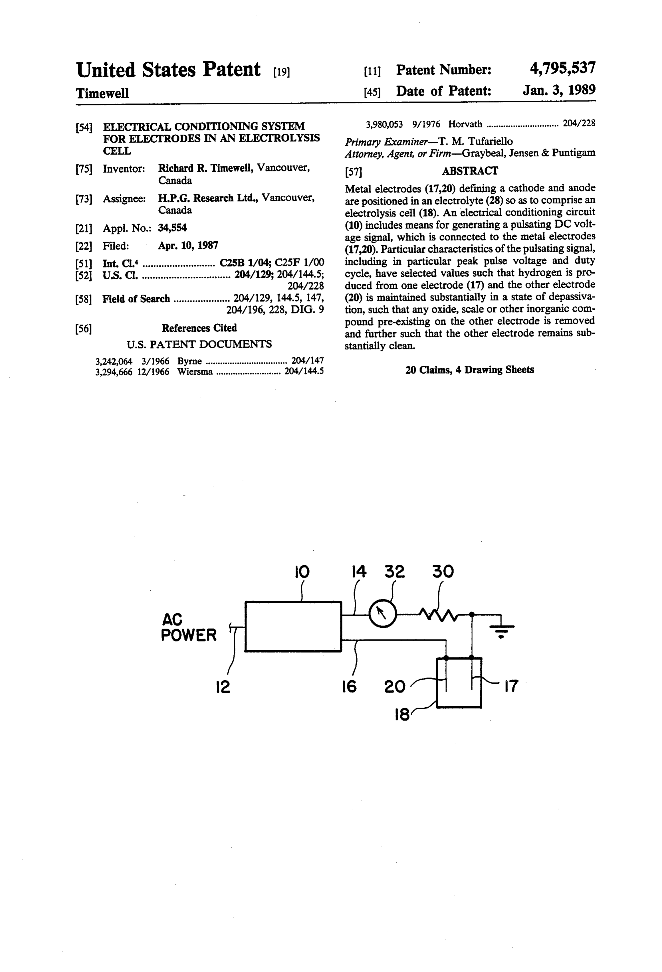
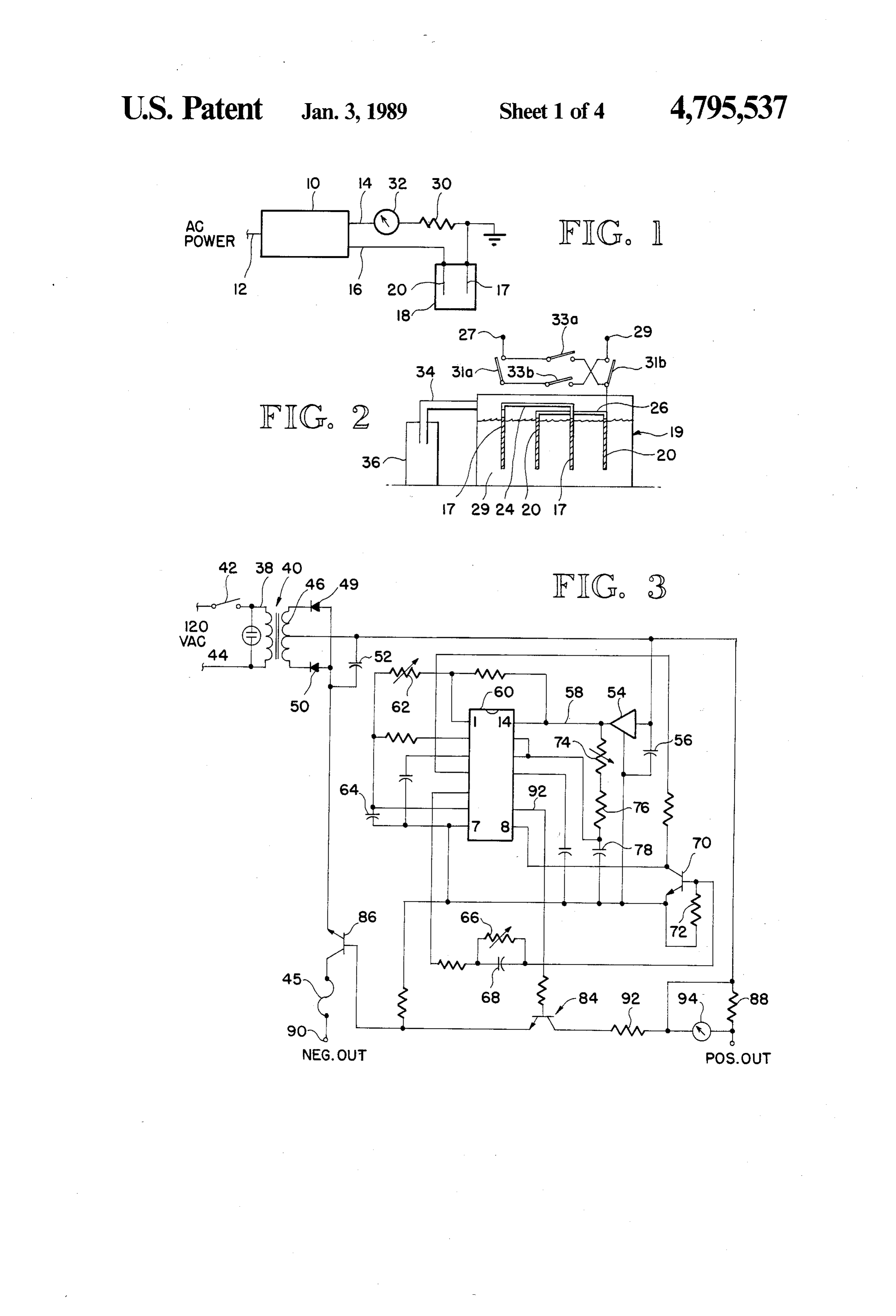
DESCRIPTION plates in which the surfaces thereof must be prepared in 1. Technical Field a particular way prior to use and/or further treatment. This invention relates generally to the art of electrol Electropolishing and pickling are but two examples of ysis, which typically involves the decomposition of an such surface preparation. Pickling, for instance, refers electrolyte by an electrical current, and more particu 10 to a process for thoroughly cleaning a metal surface, larly concerns a system in which a pulsating DC current particularly steel, but other metals as well. It usually is applied to the electrodes in an electrolysis cell. involves the dissolution of the existing oxide film or 2. Background Art scale on the steel with mineral acids such as sulfuric, In the typical operation of an electrolysis cell, an nitric, hydrochloric or hydrofluoric acids. electric current is produced and hydrogen and oxygen 5 Another somewhat related problem dealing with are produced at the negative (cathode) and positive metal surfaces is the protection of metal surfaces from (anode) electrodes, respectively, which typically are oxidation or other deterioration through electrolysis. metal plates positioned in a selected electrolyte. The This is generally referred to as cathodic protection and hydrogen and oxygen thus produced may be captured includes the protection of pipelines and hulls of vessels. and used as desired, or may be discarded, depending on 20 DISCLOSURE OF THE INVENTION the particular application. Many different electrolysis systems are known. Typically, the electrodes are at a Accordingly, the present invention, in one aspect, different potential, resulting in a DC current between includes a method and apparatus for electrically condi the two electrodes and hence an electric current output tioning electrode means positioned in an electrolyte. from the cell. The electrode means includes at least one metal elec In some applications, an external current is applied to 25 trode which includes cathodic and anodic portions. A the electrodes. One example of such an apparatus, pulsating DC voltage is generated and applied to the which includes the use of a pulsed DC current, is shown electrode means. The signal has particular characteris in U.S. Pat. No. 3,980,053 to Horvath. Horvath's pulsed tics with values selected such that hydrogen is pro DC signal, however, is characterized by a high fre duced at the cathodic portion of the electrode means quency and a high current. The apparatus is inefficient, 30 and and could be quite dangerous in actual operation. The trodefurther such that the anodic portion of said elec object of the Horvath apparatus is the production of depassivation.is maintained substantially in a state of means both hydrogen and oxygen. The electrode which pro In another aspect, at least one of the portions of the duces the oxygen is maintained in a state of passivation. electrode means has a coating thereon, such as an oxide The inexpensive, safe production of hydrogen is be 35 or other inorganic film or other scale, and the particular coming increasingly desirable because hydrogen, in characteristics of the signal are selected such that the addition to other light hydrocarbon gases such as pro coating is removed from the one portion upon applica pane and butane, is becoming more popular as an inex pensive and clean burning source of energy. Efficiency tion of such signal to the electrode means. Further, in is thus an important issue in the production of hydro such a method, the one portion of the electrode means gen, although most existing systems for producing hy is thereafter maintained in a state of depassivation. drogen, particularly systems which operate on a rela BRIEF DESCRIPTION OF THE DRAWINGS tively small scale, are quite inefficient as well as expen FIG. 1 is a simplified schematic representation of the sive. Further, such systems are often difficult to ade combination of the electrode conditioning system of the quately monitor to maintain safety. These disadvan 45 present invention and an electrolysis cell. tages, in addition to others, have resulted in a lack of FIG. 2 is a simplified diagram of an electrolysis cell emphasis and subsequent success in the commercial production of hydrogen with electrolysis technology. and related chamber for storing hydrogen. FIG. 3 is an electrical schematic of the electrode
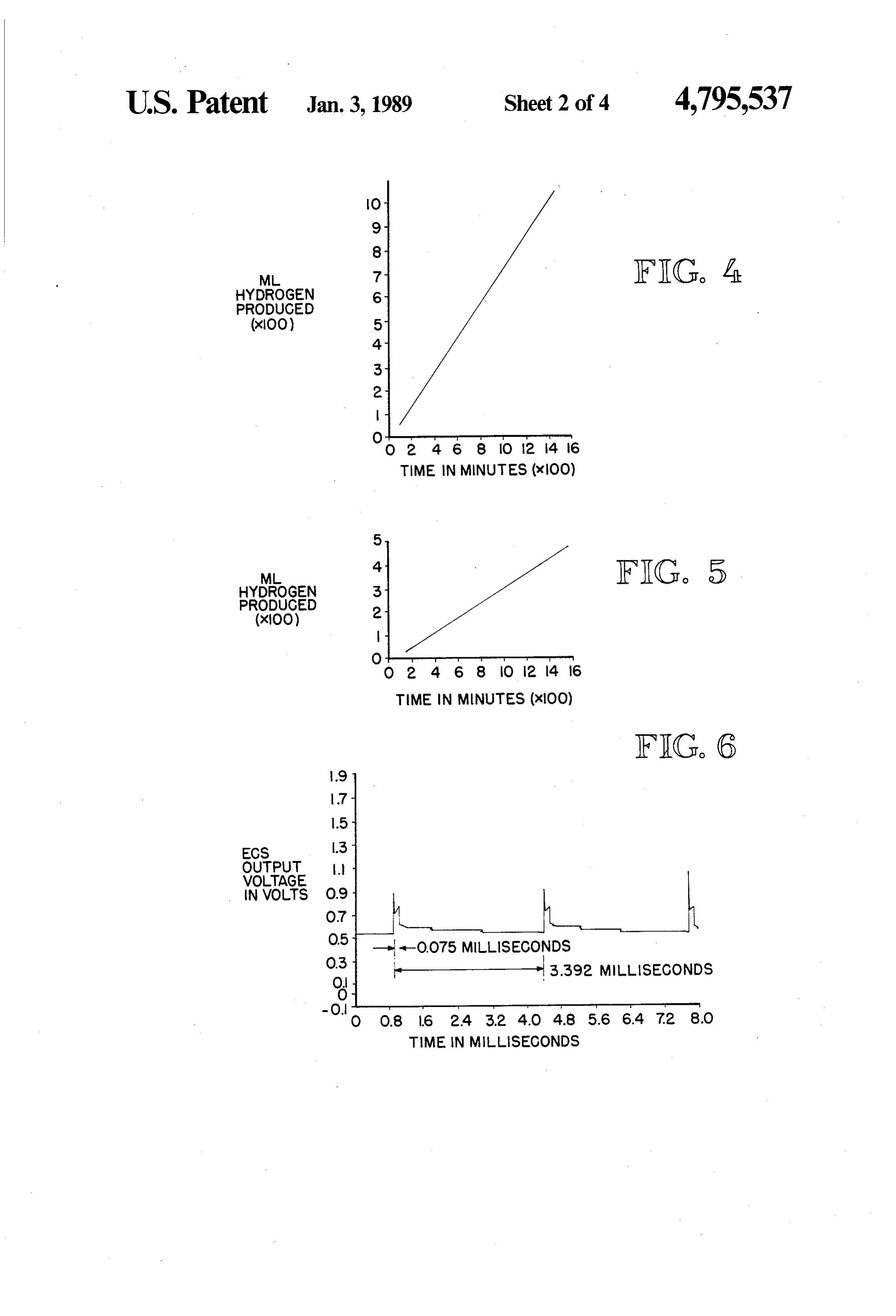
In a somewhat related technological area, there is conditioning also a continuing need for inexpensive and reliable 50 system of the present invention. methods for removing oxides or scale or other film or FIG. 4 is a graph showing production of hydrogen coating of inorganic compounds from metal plates, as against time for one embodiment of the present inven well as a need for methods of polishing or otherwise tion using the circuit of FIG. 3 and using aluminum preparing the surfaces of metal plates in some fashion electrodes in the electrolysis cell.
for plating and the like. Metal plates typically develop 55 FIG. 5 is a graph showing the production of hydro oxide coatings or other electrically nonconductive films gen against time for another embodiment of the present in use. In automobile batteries, for instance, the lead invention using the circuit of FIG. 3 and using steel plates can become covered with an excessive amount of electrodes in the electrolysis cell.
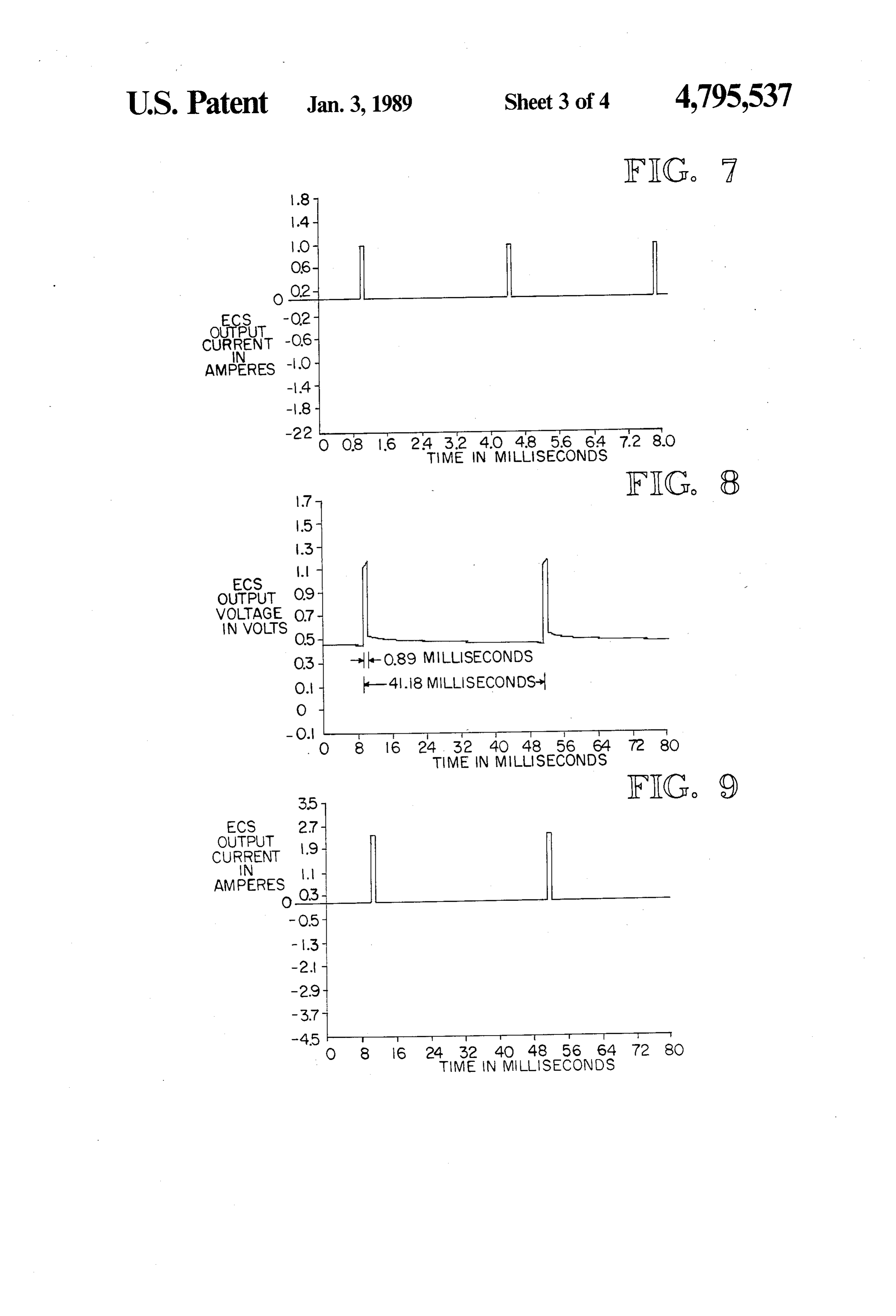
lead sulfate, to the point where the battery will cease FIG. 6 is a graph showing output voltage against time operation. This is often referred to as a state of passiv 60 for the embodiment graphed in FIG. 4. ation, in which the electrodes become in effect "pas FIG. 7 is a graph showing output current against time sive", i.e. no current flows between the plates. for the embodiment graphed in FIG. 4. Another common example of a metal oxide coating is FIG. 8 is a graph showing output voltage against time the film of rust which covers steel plates, a condition for the embodiment graphed in FIG. 5. which is undesirable in many applications. Known 65 FIG. 9 is a graph showing output current against time methods of removing such non-conductive coatings are for the embodiment graphed in FIG. 5.
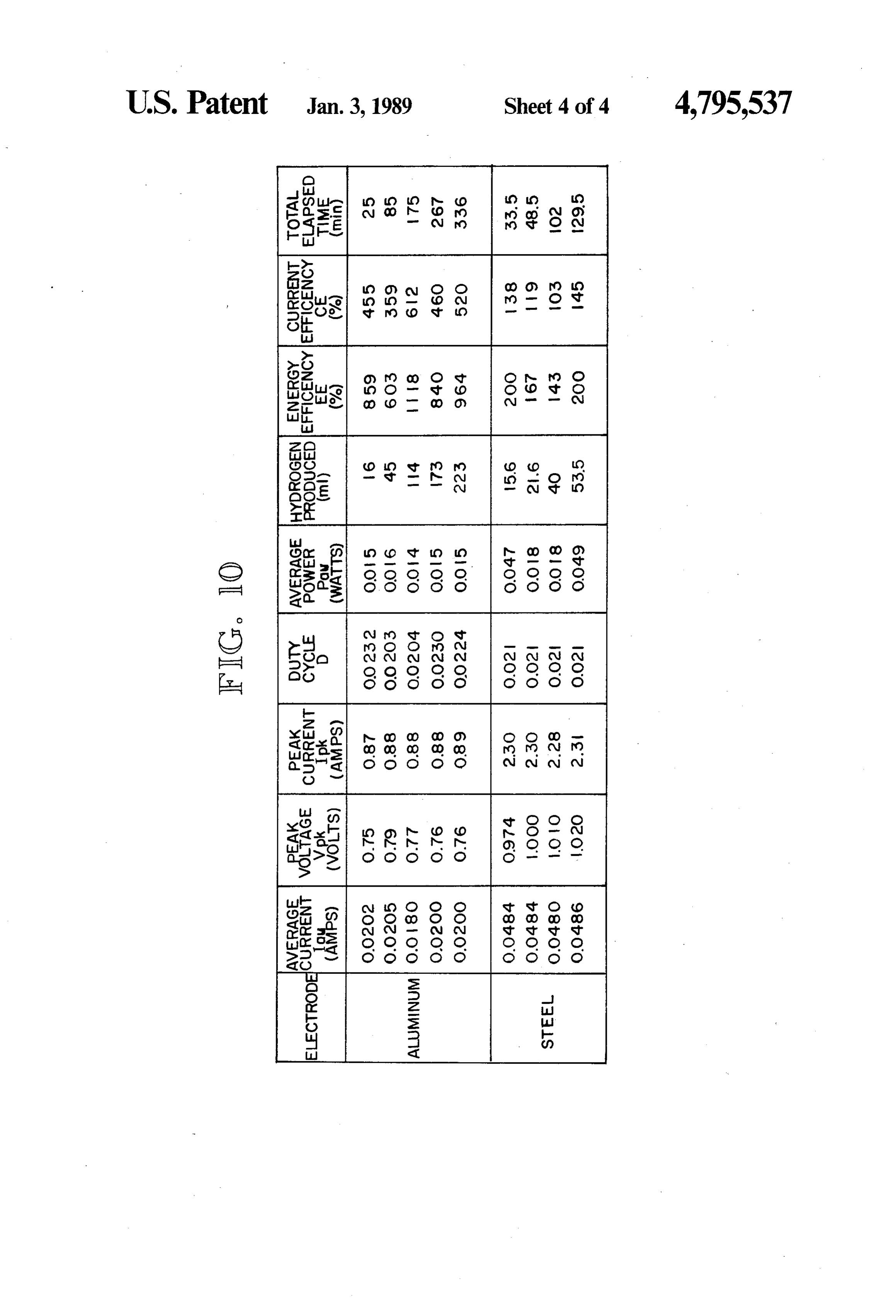
usually somewhat cumbersome and fairly expensive. FIG. 10 is a table showing results of tests conducted Therefore, there is a need for a reliable method of re on one embodiment of the system of the present inven
Page 7
tion using the circuit of FIG. 3 and both aluminum and circuit 10 and a neon bulb 44 shows the operating condi steel electrodes, respectively, in the electrolysis cell. tion. A slow-blow fuse 45 provides protection for cir cuit 10.
BEST MODE FOR CARRYING OUT THE The output of secondary 46 of transformer 40 is a 25 INVENTION 5 volt AC signal, which is full wave rectified by diodes 49 Referring to FIGS. 1 and 2, the electrode condition and 50, resulting in a pulsating DC signal of 18 volts ing system of the present invention is shown in a simpli peak. This pulsating DC signal is smoothed out by ca fied form in relation to an electrolysis cell and a cham pacitor 52 which in the embodiment shown is fairly ber for collecting hydrogen produced during operation large, on the order of 0.037 farads. This signal is applied of the system. The electrode conditioning circuit, 10 as an input to a voltage regulator comprising an opera shown as block 10 in FIG. 1, operates from a source of tional amplifier 54 and associated feedback capacitor 56. AC power 12. The output of the electrode conditioning The output of the voltage regulator is a stable 12 volt circuit 10, at lines 14 and 16, is a pulsed DC current. DC signal on line 58.
Line 14 is connected to a first set of plates 17 in an Timing circuit 60, to which the signal on line 53 is electrolysis cell which is generally shown at 18. Line 16 15 applied, generally comprises two timer circuits in a is connected to the other set of plates 20. In the embodi single integrated circuit chip. In the embodiment ment shown, plates 17 comprise the cathode and plates shown, it is an NE/SE556 manufactured by Intercell 20 comprise the anode. Corporation, or equivalent, such as TLC 556 from In the embodiment shown, the plates 17 and 20 are Radio Shack. The output of the first timer circuit, in four aluminum or steel rectangular plates approximately response to the input signal at pin 14, is a square wave, 4.3 centimeters wide, 0.1 centimeters thick and 15 centi the relative timing of the square wave being determined meters long, mounted vertically within an electrolyte by a series RC circuit comprising adjustable resistor 62 28 such that approximately 13.5 centimeters of each and capacitor 64. The square wave signal, at pin 5, in plate is submerged. The plates are 1.1 centimeters apart. turn is shaped by a parallel RC circuit comprising ad The two plates 17-17 comprising the cathode are con 25 justable resistor 66 and capacitor 68 to produce a rela nected in parallel by lead 24 while the two other plates tively short voltage spike at each point in time when the 20-20 comprising the anode are connected in parallel square wave from the timer 60 at pin 5 goes positive. by lead 26. The electrolyte 28 in which the plates are The voltage spike is used to control transistor 70 mounted is basically saltwater; in particular, approxi which, with resistor 72, forms a one-shot multivibrator mately 36 grams of table salt dissolved in 1600 milliliters 30 which in turn, when triggered, produces an output of tap water in the embodiment shown. pulse of selected duration. The width of this pulse is Also in the circuit shown in FIG. are a resistor 30 established by the values of adjustable resistor 74, resis and an ampmeter 32. The resistor is for balancing the tor 76 and capacitor 78. In the embodiment shown, circuit, if necessary, and the ampmeter is to show the resistor 76 is 220 ohms and capacitor 78 is 0.7 microfar amount of current in the circuit. Neither of those ele 35 ads. The train of pulses from capacitor 70 is applied to ments, however, are essential to the invention. transistor 84 which in turn controls output transistor 86. Extending from the electrolysis cell 18, as shown in Transistor 86 operates as an output current switch. FIG. 2, is a pipe 34 which is connected to a cylinder 36 When transistor 85 is on, a DC output of selected mag or other container. Cylinder 36 is completely filled with nitude appears between outputs 88 and 90. Transistor 86 water. Hydrogen gas which is produced by the process 40 is controlled such that the output is a pulsed DC signal described below exits from the electrolysis cell 18 having a selected pulse repetition rate and pulse width. through pipe 34 and is stored in cylinder 36. Resistor 92 and meter 94 are connected so as to provide It should be understood that the electrolysis cell por a direct indication of the average current supplied to the tion of the system described herein as well as the appa electrolysis cell.
ratus for storing the hydrogen gas produced are rela 45 Output points 88 and 90 are connected to an electrol tively conventional and that other structural arrange ysis cell, as shown in FIGS. 1 and 2. The peak voltage, ments and configurations could be used. It should be pulse repetition rate, pulse width and the duty cycle of further understood that the electrolysis cell could be the DC pulse signal at outputs 88 and 90 may be varied virtually any size, including considerably larger than by adjusting the various elements discussed above. In that described herein. The configuration of the electrol 50 the embodiment shown, one or more of these signal ysis cell in the embodiment shown is for purposes of characteristics, particularly peak voltage and duty cy illustration only. cle, are controlled, as explained in more detail below, so The electrode conditioning circuit shown in block10 that application of the signal to given electrodes in a is connected to terminals 27, 29 of the cell shown in given electrolyte will result in the production of hydro FIG. 2 to produce the desired results. When switches 55 gen at one electrode and the continuing depassivation of 31a, 31b are closed and switches 33a, 33b are open, one the other electrode.
terminal is positive and the other is negative. When In the process of depassivation, oxides and other switches 31a, 31b are open and switches 33a, 33b are surface coverings, such as a coating of inorganic mate closed, the opposite is true, so that the plates 17-17 and rial or specific debris such as rust or other scale, are 20-20 could serve, respectively, as either the cathode 60 removed from the surface, and the bare metal under or the anode in the electrolysis cell. Also, the electroly neath comprising the electrode is maintained substan sis cell could be arranged so that opposite sides of a tially in an exposed state, so that the electrode continues single plate could serve as cathode and anode, respec to discharge between successive pulses. The surface of tively, i.e. bipolar electrodes. the electrode thus "dissolves', or "corrodes' instead of The electrode conditioning circuit 10 is shown in 65 being stable. Typically, relatively little, of any, oxygen more detail in FIG. 3. 120 volts AC power is provided is produced at the depassivated electrode, so that the to the primary winding 38 of a center tapped trans electrode does not have the opportunity to "heal itself former 40. A switch 42 controls the on-off operation of through the formation of a surface oxide. Such action
Page 8
permits the use of the present invention in metal surface voltage conditioning signal shown in FIGS. 8 and 9. cleaning applications, such as surface polishing or pick Referring to FIG. 8 in particular, the peak voltage of ling of steel or other metals. These features are dis the pulses is 1.2 volts, which is somewhat greater than cussed in more detail below, as well as the high energy the peak voltage for the aluminum electrode embodi and current efficiencies possible with the present inven 5 ment. The pulse width, at 0.89 milliseconds, is substan tion, because of the volume of hydrogen produced with tially wider than for the aluminum electrode embodi relatively low current input. ment, although the duty cycle of the signal is approxi FIGS. 4, 6 and 7 are graphs showing the results ob mately the same. The peak current of the pulses is also tained from a conbination comprising the electrolysis greater, approximately 2.5 amps as opposed to 1.0 amps. cell and the electrode conditioning system described O The energy efficiency, however, is still up to 100% and above, using aluminum electrodes in the electrolysis even greater.
cell. FIG. 5 shows generally the production of hydro The reaction at the anode is Fe-2e -Fe2+, while gen over time with respect to the electrode condition the reaction at the cathode is 2H --2e-H2. The ing circuit of FIG. 3, while the signal output (voltage overall reaction is Fe-2H2O-Fe(OH)2+H2. Again, and current against time) to the electrolysis cell is 15 very little oxygen is produced at the stated peak voltage shown in FIGS. 6 and 7.
levels. However, higher peak voltages will result in
Referring to FIG. 6 in particular, the circuit of FIG. production 3 is arranged to produce a voltage pulse of approxi be produced.of Fe(OH)3 and at still higher levels, O2 will mately 0.7 volts peak with pulse width of 0.075 millisec onds. The time between successive pulses is 3.39 milli 20 The present invention has very high energy and cur seconds, resulting in a duty cycle of approximately 0.02. rent efficiencies. FIG. 10 is a table which shows a repre The corresponding signal current levels are shown in sentative sample of results of tests on the combination of FIG. 7. the electrolysis cell and the electrode conditioning sys Operationally, in response to the electrical signal of tem of FIG. 3, with the output signal being in accor FIG. 6, one set of aluminum plates is polarized as the 25 dance with FIGS. 6-9. FIG. 10 also shows corre cathode, and the other is polarized as the anode, result sponding calculations for energy efficiency and current ing in the production of a form of aluminum oxide, such efficiency, using the obtained values for current and as Al2O3 or AlOH)3 at the anode and hydrogen. at the voltage.
cathode. During the interval between successive elec The known formula for current efficiency (CE), in trical pulses from the circuit of FIG. 3, the reaction of 30 percent, relative to hydrogen production is: the electrodes in the electrolysis cell continues without external electrical power being applied.
The production of hydrogen and aluminum hydrox CE 8.616 H(60)(100)
ide during the interval between externally applied elec 14.36H trical pulses is referred to as electrolysis discharge, i.e. 35 Iay(t) the electrodes are in fact "discharging'. Repolarization refers to that interval of time during which the electri where His in milliliters for a particular time interval (t) cal pulses are applied to the electrodes, i.e. at intervals in minutes and Iay is in amperes. Further, from Perry's of 3.39 milliseconds in FIG. 6.
It has been found, as pointed out above, that the DC Chemical Engineering Handbook, it is known that 325 pulse pattern shown in FIG. 6 prevents the passivation BTU/cuft is the maximum fuel value of hydrogen. This of the aluminum electrodes and assures the continuing is equivalent to 0.00336 watt hr/ml of hydrogen. Thus, electrolysis discharge of the cell. The surface of the energy efficiency (EE), in percent, is: electrodes is maintained essentially bare, and relatively little, if any, oxygen is produced. 45
The peak voltage of FIG. 6 is in the embodiment EE Iay (pk)(i) shown sufficient to produce Al(OH)3. This value of 20.16H peak voltage appears to be a minimum driving voltage Iay(Vpk)(i) to sustain the reaction for aluminum electrodes. At a sufficiently higher peak voltage, different aluminum 50 As shown in FIG. 10, energy efficiencies for the oxides or hydroxides or even oxygen will be produced, present invention can be 100% or even much higher in which may be desirable in particular applications. How particular ever, it is advantageous in many applications to main using othercircumstances.
metals as
Other circuit configurations, electrodes and other electrolysis tain the voltage and current levels relatively low so as cell configurations, may have somewhat different effi to maximize energy efficiently and not produce oxygen. 55 ciencies.
The reaction at the anode in the embodiment shown is 2Al-6e-->2Ali, while at the cathode the reaction purpose In the above-identified embodiments, one primary is 6H + 6e ->3H2. The overall reaction is 2Al--6- is to produce high quality hydrogen at a high H2O-2Al(OH)3-3H2. In this embodiment, it can thus embodiments energy efficiency and in a relatively safe manner. These be seen that relatively small amounts, if any, of oxygen 60 have applications which include, among are produced. Besides other advantages dealing with others, a portable fuel cell, in which hydrogen gas is the cleaning and depassivation, as discussed above, this energy source, or as a means for producing hydrogen increases the inherent safety of the apparatus. Oxygen directly at a remote site, which eliminates the need to could be produced, if desired, by increasing the driving transport hydrogen to the site.
voltage to required known levels. 65 In addition to the production of hydrogen, the inven Similar graph information is provided for conven tion can be used as a relatively low cost means of pro tional high quality steel electrodes, in FIGS. 5, 8 and 9. ducing different metal hydroxides or oxides, such as FIG. 5 shows production of hydrogen vs. time for the aluminum hydroxide, depending upon the metal used
Page 9
for the electrodes. Such hydroxides/oxides have a num 5. An apparatus of claim 1, wherein the cathodic and ber of different commercial uses. anodic portions of said electrode means comprise sepa In other applications involving the present invention, rate sections of said one metal electrode. energy or current efficiency perse may not be the most 6. An apparatus of claim 1, wherein the electrode important factor. For instance, in applications involving 5 means includes at least two metal plates, one plate being surface treatment of metals, including specifically the the cathode portion and the other plate being the anode removal of metal oxides or inorganic compound or portion.
other scale or debris, such as rust, from plates, or in 7. An apparatus of claim 1, including switching means pickling steel or other metal, or in the reconditioning of to selectively reverse the polarity of the pulsating DC batteries by removing lead sulfate from the plates, or in O voltage signal.
metal deplating, or in electropolishing or etching to 8. An apparatus of claim 1, wherein said signal gener clean and prepare a metal surface, especially for further ating means includes means for producing a series of treatment, such as plating, factors other than high en square wave pulses, means for controlling the pulse ergy efficiency are quite important. The principles of 15 duration and pulse repetiton rate of said square wave the present invention can be used to provide a fast, pulses, and means using said square wave pulses to inexpensive and convenient means to accomplish the control the connection of a source of DC voltage of above functions. This is done by adjusting the one or selected magnitude to the electrode means. more characteristics of the signal, i.e. the duty cycle, 9. An apparatus of claim 8, including means for vary peak voltage, and pulse repetition rate to suit the partic 20 ing the peak voltage, the duty cycle and the pulse repe ular application. With respect to the duty cycle, for tition rate of said pulsating DC voltage signal. instance, a normal range of adjustment would be be 10. An apparatus for electrically conditioning an tween somewhat below 2% to 10%, with the higher electrode means which includes at least one metal elec duty cycle resulting in lower efficiencies. However, in trode, the electrode means being positioned in an elec certain applications, such as pickling steel and recondi trolyte and including cathodic and anodic portions, at tioning lead-acid batteries, the duty cycle will typically 25 least one of the portions having a coating on at least a be higher, i.e. 35%, with a possible range of 30%-40%. part thereof such as an oxide or other inorganic film, the Still further, the principles of the present invention apparatus comprising:
can be used to provide cathodic protection for pipelines means for generating a pulsating DC voltage signal, and boats, by adjusting the current to a level sufficient 30 wherein particular characteristics of the signal to stop or significantly reduce corrosion of the cathodic have values selected such that when the pulsating element. DC voltage signal is applied to the electrode Although a preferred embodiment of the present means, hydrogen is produced off the cathodic por invention has been disclosed herein for illustration, it tion of the electrode means and substantially no should be understood that various changes, modifica 35 oxygen is produced off the anodic portion; tions and substitutions may be incorporated in such means for selectively reversing the polarity of the embodiment without departing from the spirit of the pulsating DC voltage signal; and invention as defined by the claims which follow. means connecting the pulsating DC voltage signal to claim:
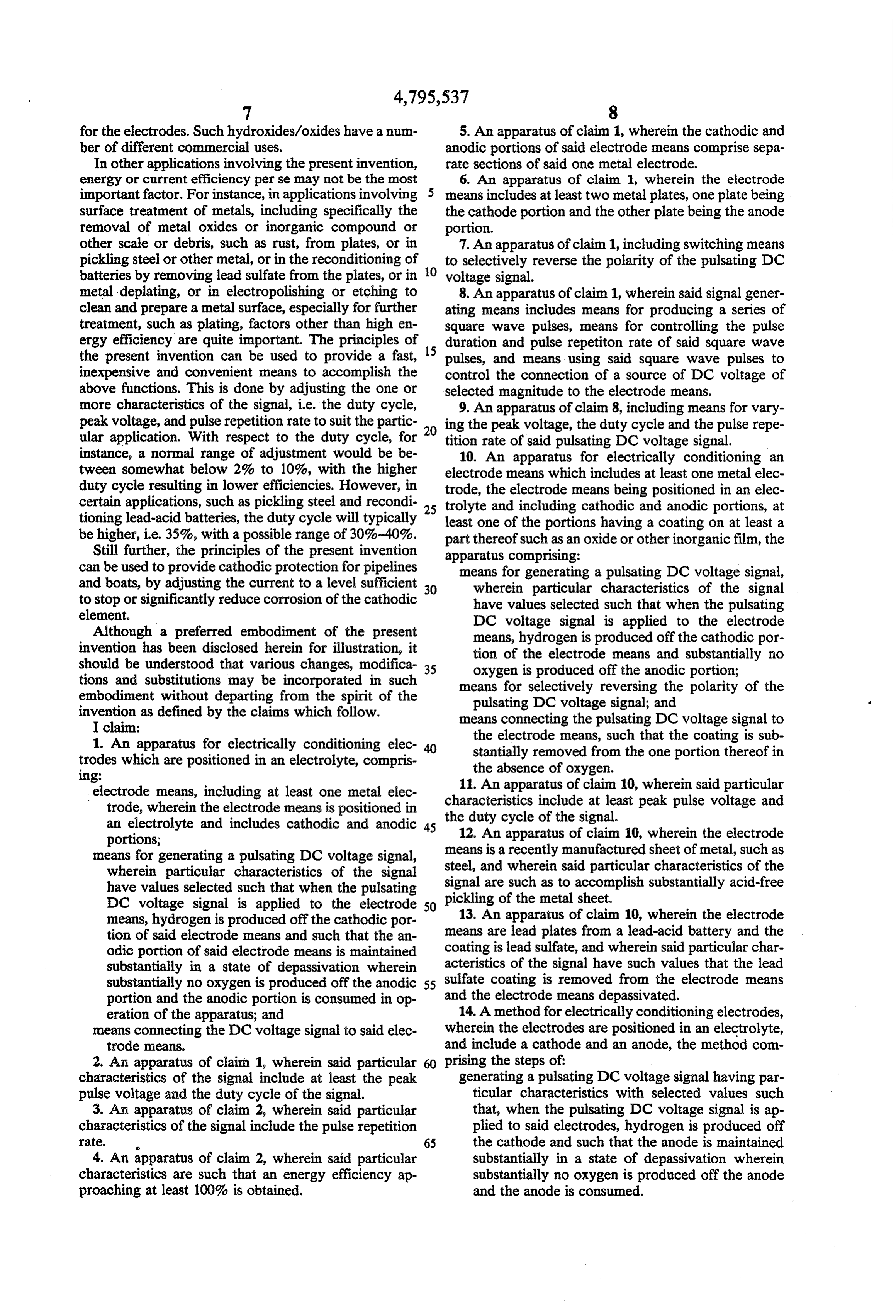
1. An apparatus for electrically conditioning elec the electrode means, such that the coating is sub trodes which are positioned in an electrolyte, compris stantially removed from the one portion thereof in 1ng: the absence of oxygen.
electrode means, including at least one metal elec 11. An apparatus of claim 10, wherein said particular trode, wherein the electrode means is positioned in the duty cycle include characteristics of the at least peak pulse voltage and signal.
an electrolyte and includes cathodic and anodic 45 12. An apparatus of claim i0, wherein the electrode portions;
means for generating a pulsating DC voltage signal, means is a recently manufactured sheet of metal, such as wherein particular characteristics of the signal steel, and wherein said particular characteristics of the have values selected such that when the pulsating picklingareofsuch signal as to accomplish substantially acid-free the metal sheet.
DC voltage signal is applied to the electrode 50 means, hydrogen is produced off the cathodic por 13. An apparatus of claim 10, wherein the electrode tion of said electrode means and such that the an means are lead plates from a lead-acid battery and the odic portion of said electrode means is maintained coating is lead sulfate, and wherein said particular char substantially in a state of depassivation wherein acteristics of the signal have such values that the lead substantially no oxygen is produced off the anodic 55 sulfate coating is removed from the electrode means portion and the anodic portion is consumed in op and the electrode means depassivated.
eration of the apparatus; and 14. A method for electrically conditioning electrodes, means connecting the DC voltage signal to said elec wherein the electrodes are positioned in an electrolyte, trode means. and include a cathode and an anode, the method com 2. An apparatus of claim 1, wherein said particular 60 prising the steps of:
characteristics of the signal include at least the peak generating a pulsating DC voltage signal having par pulse voltage and the duty cycle of the signal. ticular characteristics with selected values such 3. An apparatus of claim 2, wherein said particular that, when the pulsating DC voltage signal is ap characteristics of the signal include the pulse repetition plied to said electrodes, hydrogen is produced off rate. 65 the cathode and such that the anode is maintained 4. An apparatus of claim 2, wherein said particular substantially in a state of depassivation wherein characteristics are such that an energy efficiency ap substantially no oxygen is produced off the anode proaching at least 100% is obtained. and the anode is consumed.
Page 10
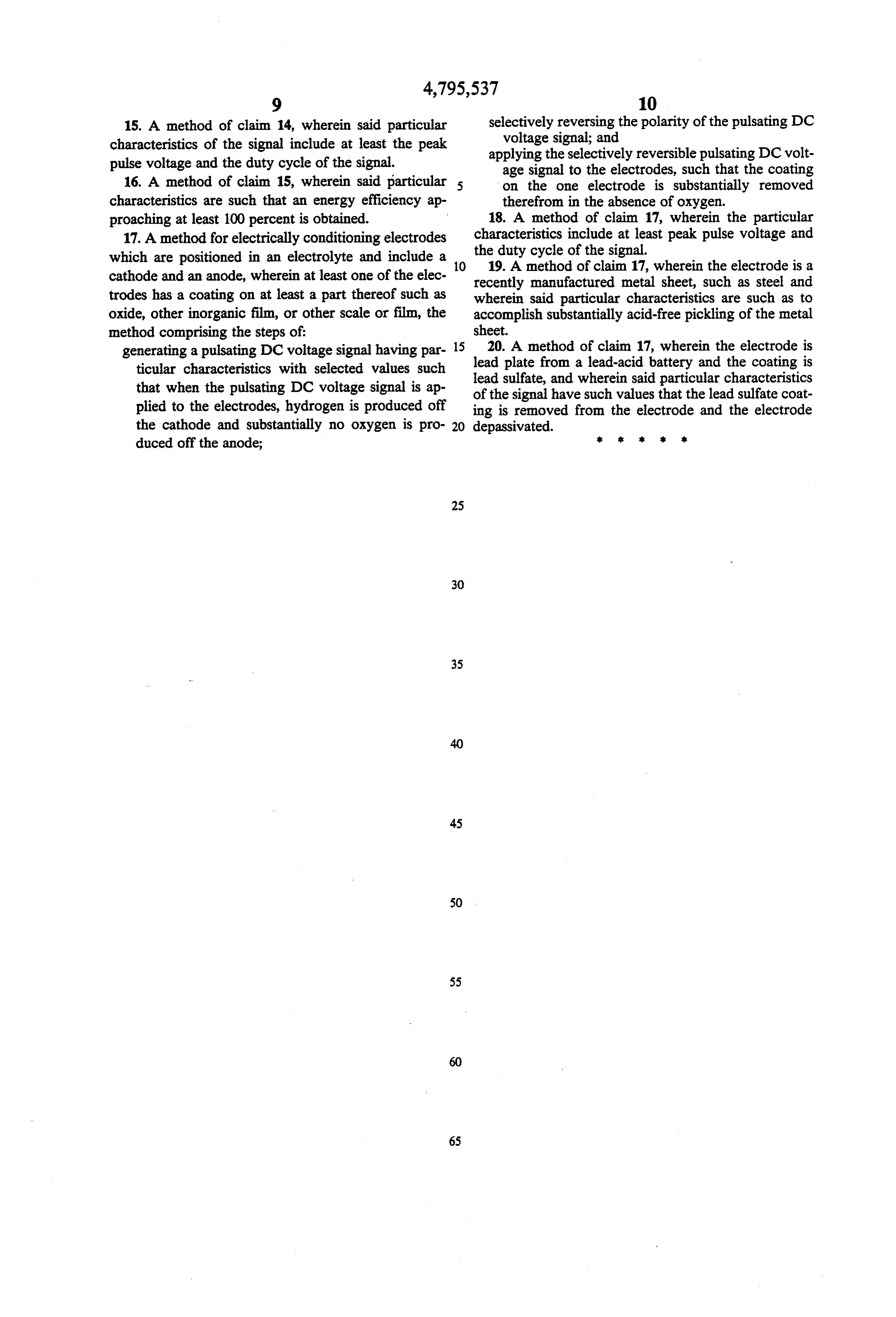
15. A method of claim 14, wherein said particular selectively reversing the polarity of the pulsating DC characteristics of the signal include at least the peak voltage signal; and pulse voltage and the duty cycle of the signal. applying the selectively reversible pulsating DC volt age signal to the electrodes, such that the coating 16. A method of claim 15, wherein said particular on the one electrode is substantially removed characteristics are such that an energy efficiency ap therefrom in the absence of oxygen. proaching at least 100 percent is obtained. 18. A method of claim 17, wherein the particular 17. A method for electrically conditioning electrodes characteristics include at least peak pulse voltage and which are positioned in an electrolyte and include a 10 the duty cycle of the signal. cathode and an anode, wherein at least one of the elec 19. A method of claim 17, wherein the electrode is a recently manufactured metal sheet, such as steel and trodes has a coating on at least a part thereof such as wherein said particular characteristics are such as to oxide, other inorganic film, or other scale or film, the accomplish substantially acid-free pickling of the metal method comprising the steps of: sheet.
generating a pulsating DC voltage signal having par 15 20. A method of claim 17, wherein the electrode is ticular characteristics with selected values such lead plate from a lead-acid battery and the coating is that when the pulsating DC voltage signal is ap of lead sulfate, and wherein said particular characteristics the signal have such values that the lead sulfate coat plied to the electrodes, hydrogen is produced off ing is removed from the electrode and the electrode the cathode and substantially no oxygen is pro- 20 depassivated.
duced off the anode;
Provenance
- Collection
- Cited prior art
- Original PDF
- patentimages.storage.googleapis.com →
- Filed
- 1987-04-10
- Pages
- 10
- Method
- pdftotext (the PDF's own text layer) + pdftoppm 300dpi page scans
- Source
- Google Patents bibliographic record
- Granted
- 1989-01-03
- Inventors
- Richard R. Timewell; H P G Research Ltd
- Transcribed from
- patentimages.storage.googleapis.com →