patent · US6031737
AC-DC power supply
29 February 2000
Page 1 — bibliographic record
United States Patent (19) 11 Patent Number: 6,031,737 Green (45) Date of Patent: Feb. 29, 2000 54 AC-DC POWER SUPPLY 4,833,584 5/1989 Divan ........................................ 363/37 4,931,919 6/1990 Nguyen et al ... 363/37 75 Inventor: Andrew William Green, 5,138,544 8/1992 Jessee ............. ... 363/43 Malsburg-Marzell, Germany 5,189.602 2/1993 Callier et al. ... 363/28 5,255,178 10/1993 Liberati ..................................... 363/37 rr. A 5,587,892 12/1996 Barrett ...................................... 363/44 73 ASSignee: legs New Zealand Limited, New 5,631,818 5/1997 Johnson et al. . 363/126 5,748,458 5/1998 Ochiai ......... ... 363/17 21 Appl. No.: 09/051,991 5,771,162 6/1998 Kwon ........................................ 363/97 22 PCT Filed: Oct. 24, 1996 Primary Examiner Adolf Deneke Berhane 86 PCT No.: PCT/NZ96/00119 Attorney, Agent, Or Firm Akin, Gump, Strauss, Hauer & Feld, L.L.P.
S371 Date: Sep. 1, 1998 57 ABSTRACT
An AC-DC power Supply System for receiving a three phase 87 PCT Pub. No.: WO97/17753 mains Supply and outputting a transformed DC Supply. The PCT Pub. Date: May 15, 1997 power Supply unit has a rectifier circuit (30) providing an 9 output to a three phase inverter circuit (40) to generate a 30 Foreign Application Priority Data pseudo AC three phase output of higher frequency than the AC supplied to the rectifier circuit (30). A three phase
Oct. 24, 1995 NZ New Zealand ........................... 28O317 transformer (60) receives the pseudo AC three phase output (51) Int. Cl. ............................................... H02M 5/458 and transforms the output to a three phase rectifier circuit 52 U.S. C. ... ... 363/37; 363/95; 363/131 (70) to generate the output DC supply. The inverter circuit 58 Field of Search .................................. 363/17, 34, 37, (40) provides a three leg bridge structure with each leg 363/40, 44, 84, 95, 56, 125, 131 having a Switching device one of which is used to provide s Is Y- Is - as a sys s a phase reference whereas the other two legs control the 56) References Cited relative phase shift on each leg to reduce the phase shift relative to the phase reference on one leg and increase the
4,084.205 4/1978 Bohnert ..................................... 361/76 4,567,420 1/1986 Beck ....................................... 318/803 12 Claims, 7 Drawing Sheets
CONROLER
Page 2
Drawing sheet — no readable text.
Page 3
Drawing sheet — no readable text.
Page 4
Drawing sheet — no readable text.
Page 5
Drawing sheet — no readable text.
Page 6
Drawing sheet — no readable text.
Page 7
Drawing sheet — no readable text.
Page 8
Drawing sheet — no readable text.
Page 9
AC-DC POWER SUPPLY a Second three phase rectifier circuit receiving the trans formed pseudo AC three phase output from the trans
BACKGROUND TO THE INVENTION former and generating the output DC Supply. Accordingly,
This invention relates to an AC-DC power Supply and, in a controllable three in a Second aspect, the invention comprises particular, although not necessarily Solely, to a power Supply 5 Supply phase inverter circuit receiving a DC to produce a three phase pseudo AC output Supply that is Suited to provide the necessary DC Supply for an wherein the inverter comprises:
electrolysis cell unit for the electrolysis of water to liberate a three leg bridge Structure; hydrogen and oxygen gas. However, generally the invention each leg of Said bridge Structure comprising at least one is Suited to any particular application where an AC mains controllable Switching device; Supply is available but a DC Supply is required. at least one Switching device of one of Said legs forming The full wave rectification of a multi-phase AC power a phase reference; and
Supply to produce a pseudo DC output is commonly known. wherein the voltage of the inverter circuit is controlled by For a 240 V, 50 Hz single phase mains power Supply, the means of Phase Modulation. average DC voltage produced by a full wave (H-bridge 15 Accordingly, in a third aspect, the invention comprises a rectifier) is 216 V. However, loads requiring a DC power Soft-Switching three phase inverter circuit receiving a DC Supply typically require much lower Voltages. input Supply and generating a pseudo AC three phase output For electrolysis cell units Such as the applicant's AQUA Supply wherein Said inverter circuit comprises: GAS 3 gas generator, a DC voltage in the order of 33 V is at least two Switching devices per phase; required. In order to accommodate this requirement, it has each Said Switching device having a capacititve element conventionally been the case that the AC mains Supply is connected in parallel acroSS it and each phase of the transformed to an appropriate lower level before rectifica output Supply including an inductive element; tion so that the desired output DC voltage is realised. The a respective capacitive element and inductive element of disadvantage with Such a technique is that mains frequency each phase forming a LC resonant circuit; and transformers of a power rating above 10 kW become physi 25 wherein the turn-off of each Said Switching element is cally large and heavy due to magnetic circuit and leakage controlled to have a deadtime between Switching reactance considerations. phases during which time Said LC resonant circuit Another known technique to generate a desired DC Sup causes the next Sequential Switching element that is to ply from a fixed mains AC Supply is to utilise controlled be turned on to have Substantially Zero Voltage acroSS Switching devices in the rectifier bridge. These may be it at the time of Switching. Accordingly, in a fourth aspect, the invention comprises a devices such as power transistors, SCRs or GTOs. The method for controlling the output voltage of a three phase average DC output can be adjusted by controlling the turn-on (and possibly also the turn-off) time for the Switch inverter assigning circuit comprising the Steps of a first phase as a phase reference;
ing devices. The disadvantage with this technique is that the output wave form is "lumpy” even if Smoothing Storage 35 controlling the relative phase shift of one of the other two capacitors are used across the DC output. Certain loads are phases So that a phase difference is reduced; and Sensitive to time-varying changes in the DC voltage level. controlling the relative phase shift of the third phase SO This includes Such DC machines as electrolysis cell units. that the phase difference between the third phase shift Some may be Sufficiently Sensitive as to reach the point of and the first phase is increased. not operating Satisfactorily with Such an output wave form. 40 Further aspects of this invention will become apparent to those skilled upon reading the description of the preferred
There are other problems associated with a known power embodiments.
Supply of the type having a single phase AC Supply, a
Step-down transformer and a controlled rectifier bridge BRIEF DESCRIPTION OF THE DRAWINGS circuit. These include high transformer inrush current on Preferred embodiments of the present invention will now Start-up and a Susceptibility to phase imbalances if two 45 be described with reference to the accompanying drawings phases of a nominal three phase Supply are utilised rather in which:
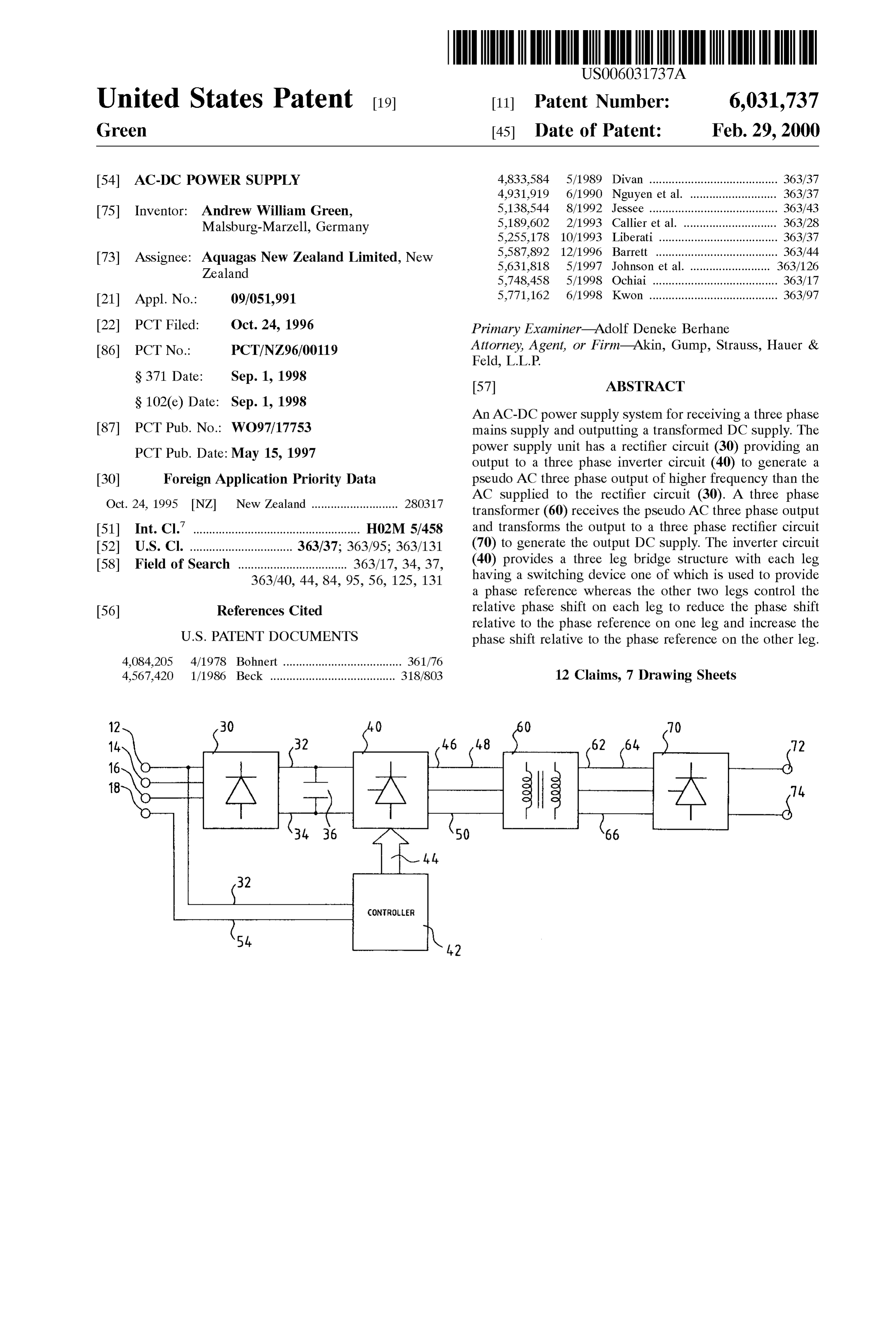
than one phase and neutral, or all three phases. FIG. 1; is a schematic block diagram of an AC/DC power
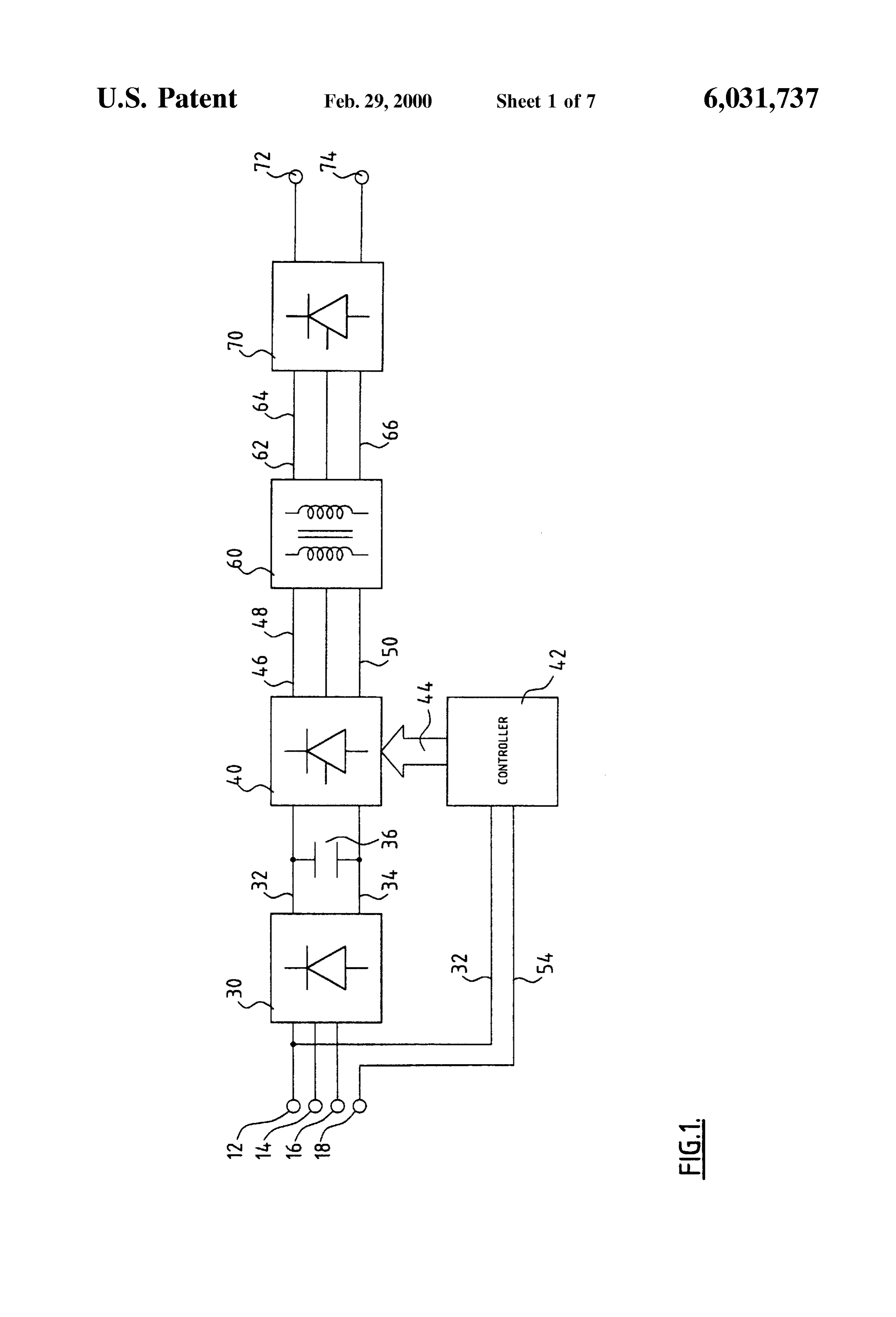
FIG. 2, is a Schematic circuit diagram of the power Supply
Therefore, it is an object of the present invention to 50 of FIG. 1;
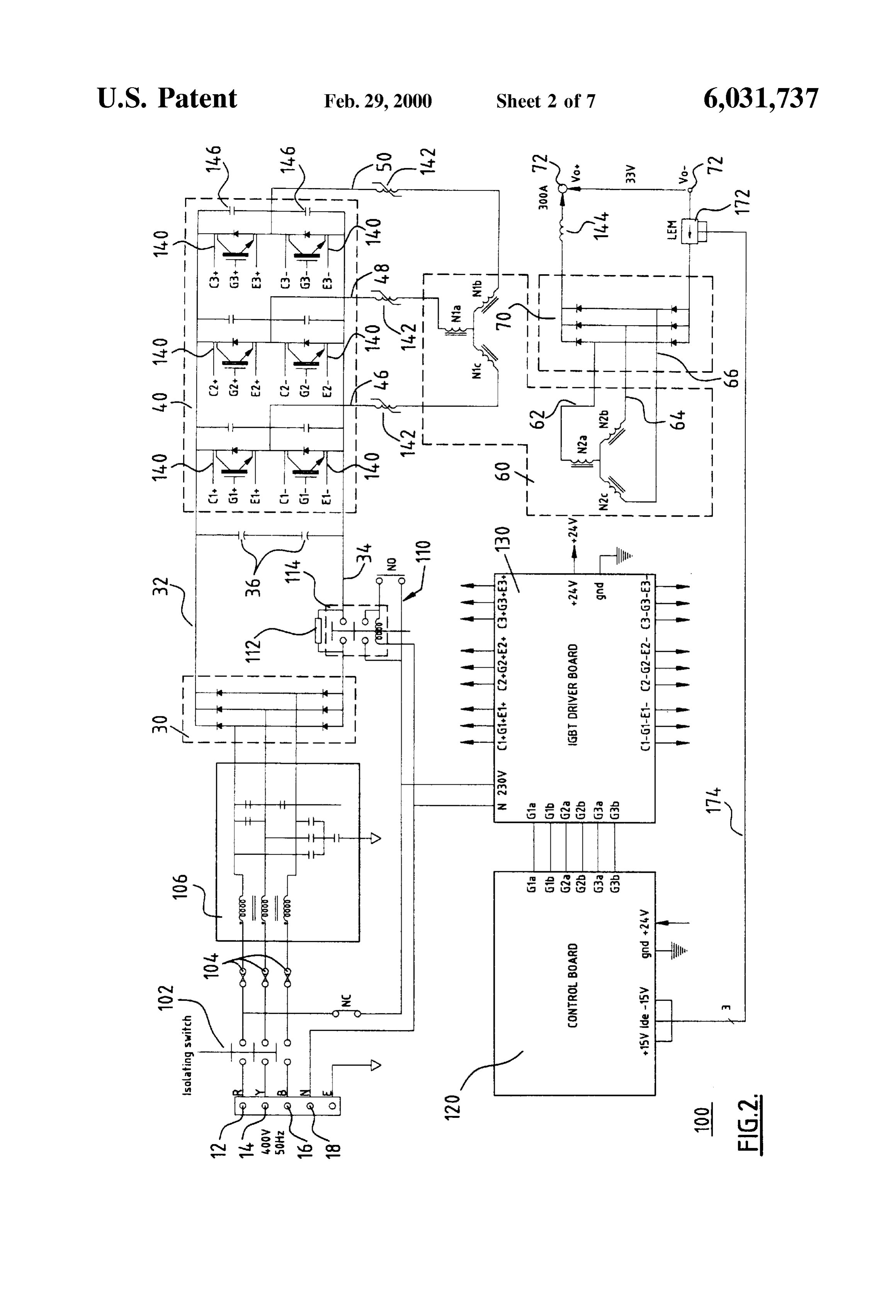
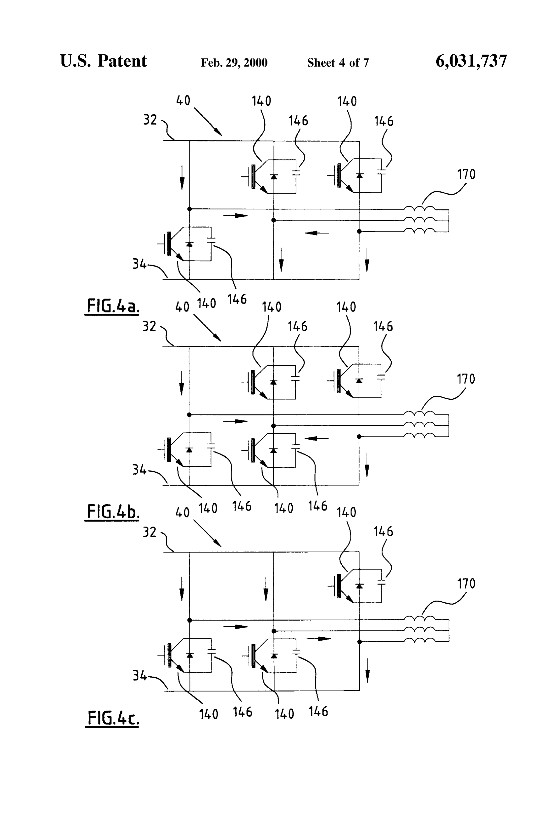
provide an AC-DC power Supply that overcomes Some of FIGS. 3a and 3b respectively are a plan view and a the disadvantages of the prior art or at least provides the croSS-Sectional view of a coaxial three phase transformer; public with a useful choice. FIGS. 4a to 4c are diagrams of the Switching state for the SUMMARY OF THE INVENTION 55 controller inverter Stage;
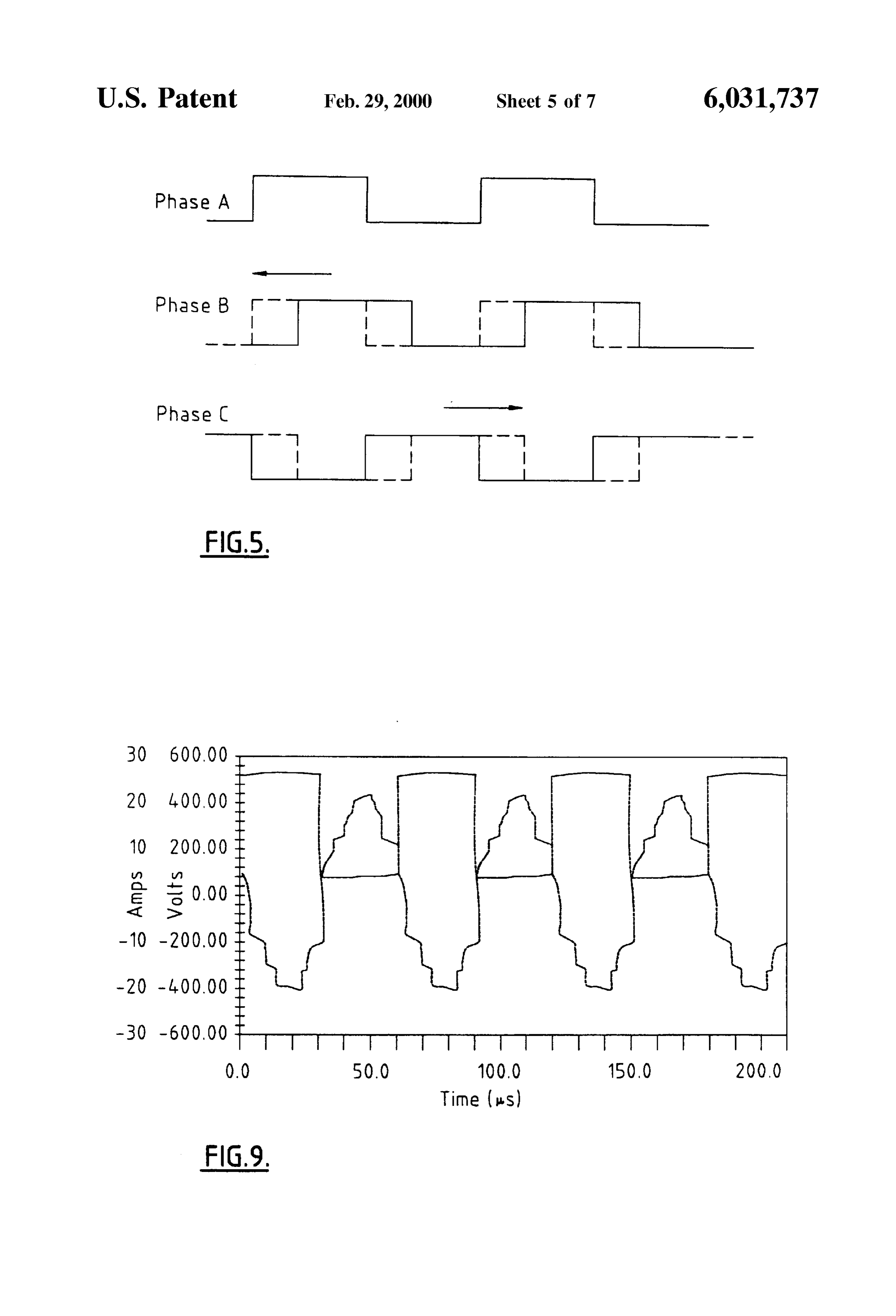
Accordingly, in a first aspect, the invention consists in an of FIG. 5; shows respective phase shift between the phases the controller inverter output;
AC-DC power Supply comprising:
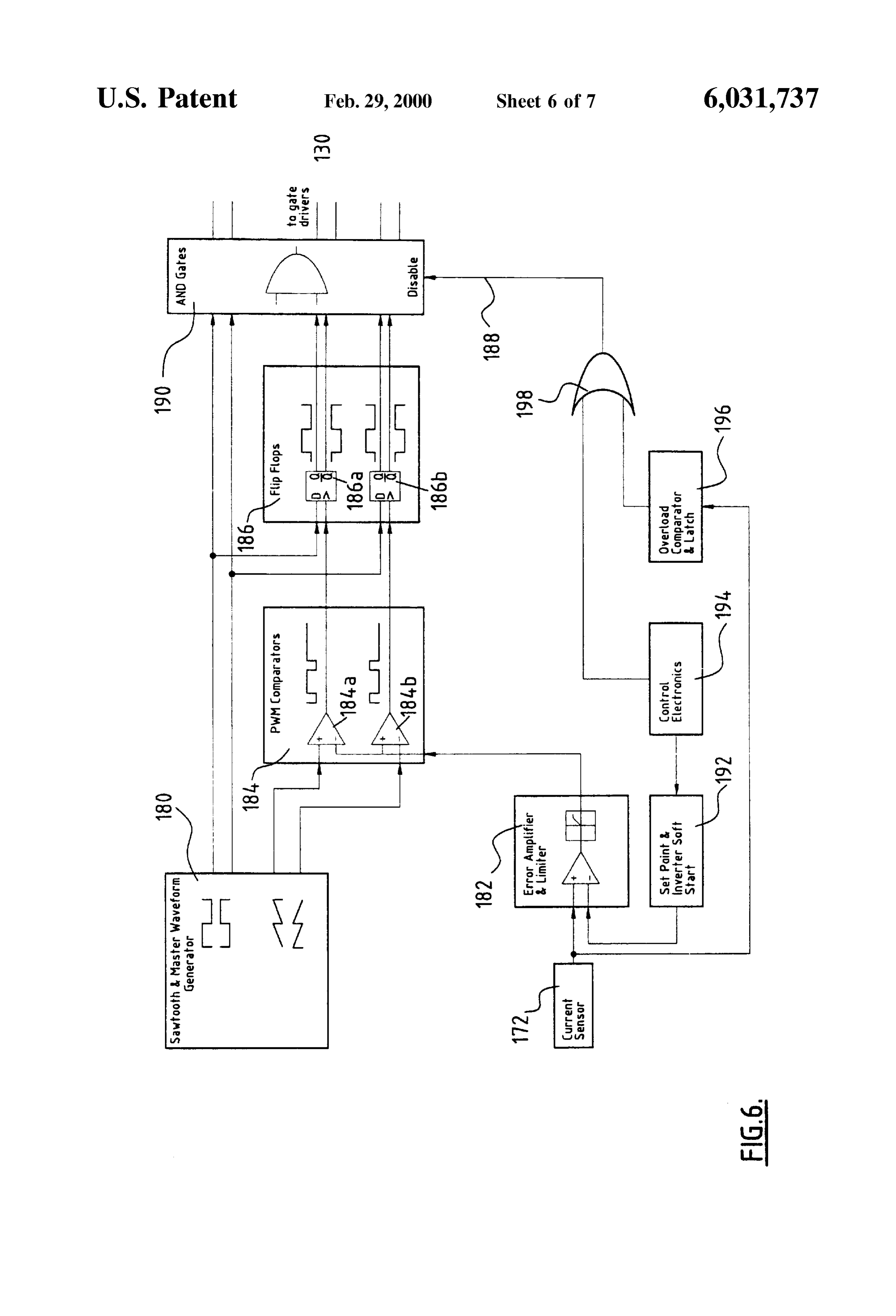
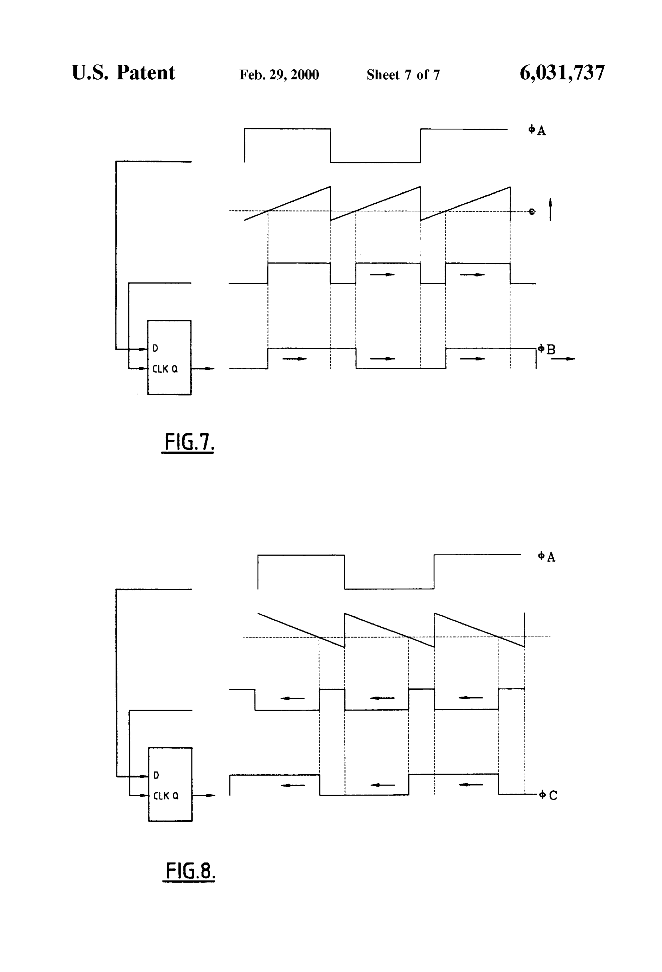
a three phase rectifier circuit generating a first rectified FIG. 6; is a schematic block diagram of the control board; output in response to an input Voltage; FIGS. 7 and 8 are timing wave forms for the gating signals 60 for the Switching devices of the inverter Stage, and a controlled three phase inverter circuit receiving the first FIG. 9; shows voltage and current waveforms for an rectified output and generating a pseudo AC three phase embodiment of the power Supply.
output having a frequency higher than the frequency of the three phase AC Supply Supplied to the rectifier DETAILED DESCRIPTION OF PREFERRED circuit; 65 EMBODIMENTS a three phase transformer receiving Said pseudo AC three FIG. 1 shows the generalised block diagram of a power phase output, and Supply 10 comprised of a number of cascaded Stages. The
Page 10
power Supply 10 receives a three phase AC Supply on input operation of the isolating Switch 102 to establish supply so terminals 12,14,16. The Supply typically is a readily avail that the bypass resistor 112 limits the inrush current due to able mains supply, which in New Zealand is a 400 V (phase transformer charging, and after a period of time is short to phase), 50 Hz Supply. Clearly other three phase Supply circuited by operation of the controlled contactor 114 caused Voltages and frequencies are contemplated including the 200 by closing of the normally opened Switch 116 that in turn is V, 60 Hz supply common in the United States. The neutral controlled by the control board 120. reference potential of the mains power Supply also is The controller inverter 40 is constituted by a full wave received on terminal 18.
A three phase rectifier Stage 30 receives the mains Supply three phase bridge circuit having Six Switching devices, in rectifying it to a DC level on the output DC bus 32.34 that one preferred form being Insulated Gate Bipolar Transistors is Supported by a storage capacitor 36 which tends to Smooth (IGBTs). One particularly preferred IBGT is the FUJI the Voltage waveform. A link inductor also can be included 6MB150F120 module containing six 50 A, 1200 V IGBT to improve the input power factor. A controlled inverter 40 Switching devices. In FIG. 2, the collector, gate and emitter receives and chops the rectified DC Supply to fabricate a electrodes are shown. Switching of the IGBT devices is pseudo three phase AC output at a frequency higher (and 15 under control of the IGBT driver board 130, in turn under typically several orders of magnitude higher) than the mains control of the control board 120. The IGBT driver board frequency. The Switching devices of the inverter 40 are 130, in turn under control of the control board 120. The controlled by control circuitry 42 coupled to the inverter 40 IGBT devices 140 have have their gate electrodes switched by multiple gating lines 44. The control circuitry 42 also in a manner to Synthesize a pseudo AC (Square-wave) three receives a reference phase-to-neutral Voltage from one of the phase output lines 44-48 of the inverter 40 contain in-line phases of the AC Supply and the mains Supply neutral, as inductors 142, the purpose of which presently will be indicated by the interconnecting lines 52,54. described.
The three phase pseudo AC output from the inverter 40 is In a particularly preferred form, the transformer 60 is a carried by output lines 46,48.50 to a (typically) step-down coaxially wound, ferrite cored type in a Star-Star configura high frequency transformer 60. The transformed pseudo AC tion. The turns ratio of the transformer 60 preferably is Voltage appearing on the output lines 62,64,66 from the 25 13.5:1, meaning that the nominal phase-phase peak voltage transformer in turn passes to a further rectifier stage 70, by on the primary of +540 results in +40 V on the secondary. which the DC output voltage for the power supply 10 is The 16 kHz, 31 V rms three phase output from the trans generated and available at the output terminals 72.74. former Secondary, appearing on the output lines 62-66, is The transformer 60 in the preferred form has a fixed turns provided to the further rectifier 70 to fabricate the output DC ratio, and therefore only approximates the desired maximum supply of a nominal 33 V level on the output terminal 72.74. output voltage appearing at the output terminals 72.74. The rectifier stage 70 is constituted by fast recovery diodes, Control over the output voltage between the full nominal Such as 6 SGS Thomson BYV225-200 diode modules. Each output and a reduced or regulated value thus is effected by module contains two 100 A 200 V diodes with reverse the control circuitry 42 controlling gating of the controlled 35 recovery times of 80ns, which are operated in parallel. The Switching devices of the inverter 40. Vo-- output terminal 72 is preceded by an in-line inductor AS previously noted, an advantage of utilising a three 144 that serves the purpose of smoothing the small AC phase mains Supply rather than a Single phase mains Supply components in the output DC current waveform. is that the effects of phase imbalance are eliminated. Returning to the co-axial transformer 60, reference is A description will now be given of a particular embodi 40 made to FIGS. 3a and b, respectively a plan view and ment of a AC/DC power Supply that is suitable for use with croSS-Sectional view of an embodiment of the transformer the present applicant's AQUAGAS generator. This is a gas 60. The transformer is constructed of three copper tubes 150 generator that can deliver 4.3 m of admixed hydrogen and soldered into three holes cut in a copper plate 152 that forms oxygen gas per hour, correspondingly consuming 17 liters of the three phase neutral (star) point. The free ends of the tubes water. A gas generator of this capacity requires approxi 45 150 form the transformer output (secondary) terminals 154, mately a 10 kW, 300 A, 33 V DC power supply. It is to be 156, 158. The copper tubes 150 thus form a single turn understood, however, that the present invention is not lim Secondary winding. Ferrite toroids are threaded over the ited to use with an electrolysis gas generator, rather equally respective copper tube 150.
has applicability in all instances where a controlled DC The three primary windings 162, 164, 166 are wound Supply is required and a three phase Supply is available. 50 through and between an adjacent pair of copper tubes 150. Other Such applications can include electric welding, A simplified representation of the primary winding 166 is electroplating, control of DC machines, battery charging, shown in FIG. 3b for clarity. The inner circumference of uninterruptable power Supplies and the like. each of the copper tubes 160 is shown in FIG. 3b for clarity. FIG. 2 shows a detailed Schematic circuit diagram for a The inner circumference of each of the copper tubes 160 power Supply 100 embodying the invention. Component 55 further includes an insulating (mylar) sleeve 168 to prevent parts common with those shown in FIG. 1 have been Short-circuiting of the primary winding to the Secondary referred to by like-reference numeral. winding formed by the respective tube. The primary winding The power supply 100 is normally rated at 10 kW (300 A, to the secondary winding are constructed of 5 mm litz wire V DC), receiving a 400 V, 50 Hz three phase AC mains (1024 strandsx40 AWG wire) and enveloped with an appro Supply. The AC Supply passes by an isolating Switch 102 and 60 priate form of heatshrink sleeving. in-line fuse links 104, and then to a conventional RFI filter The choice of a three phase configuration means that the circuit 106. The filtered three phase AC supply then passes current per Secondary winding is reduced over a single phase to the rectifier stage 30. The diodes constituting the rectifier implementation. This is an important advantage for Several Stage 30 must be rated to withstand an inverse peak voltage reasons. At 300 A, a considerable croSS-Sectional conductor of at least 540 V. The DC bus voltage level is 540 V DC. 65 area is required and this is difficult to achieve given that the A soft-start circuit 110 forms a component part of the Zero depth of copper at 16 kHz is only 0.5 mm. Furthermore, if DC reference 34 of the DC bus. This circuit acts on the transformer output is to be rectified, another difficulty
Page 11
S 6 arises in that fast recovery diodes presently are only readily this condition, in which case a Saturable inductor 142 was available in modules with ratings of up to 200 A. By use of introduced in Series with each of the transformer primary the three phase co-axial transformer, an output rating of 300 windings 162–166. This arrangement provides the necessary A is divided across the three phases. inductance to discharge the respective parallel capacitor 146 The use of a high frequency transformer allows an equiva prior to the corresponding transistor 140 Switching on, but lent power rating to be achieved before a transformer that is then Saturates during full current flow, thus introducing no an order of magnitude leSS heavy than a conventional low additional Voltage drop.
frequency transformer, and perhaps for one half of the price. AS is apparent, the Soft Switching regime does not form a This is because for a minimised core area, and a maximised part of the controlling functions effected by the control board Voltage, either the frequency or the turns must be increased. 120.
Increasing the number of turn leads to an increase in leakage Also as previously discussed, control over the output DC inductance and hence a large Voltage drop through the Voltage occurs by way of control of the gating of the transformer. transistors 140 that constitute the controllable inverter 40. One version of the transformer 60 tested as a component This function ultimately is achieved by the control board part of the power Supply shown in FIG. 2 had approximate 15 120. In particular, output DC voltage control is achieved by dimensions of 200x150x150 mm. Measurements on Such a a phase shift output control technique. transformer indicated that the coupling factor from the As shown in FIG. 5, one of the phases of the inverter 40 primary to the secondary was 99.95%, thereby indicating a (phase A") acts as the phase reference. For the full output leakage inductance of only 0.05% of the primary inductance. voltage from the inverter 40, the nominal phase difference With a higher-length-to-width ratio, an even higher coupling between the phase A, phase B and phase C is 120 respec factor of approximately 99.99% would be obtained. tively. This output Voltage level can be adjusted by adjusting The three phase inverter 40 shown in FIG. 2 is hard the thus relative phase difference between each of the phases, causing partial Voltage cancellation and thereby reduc
Switched. The means that at the instant of Switching on, each transistor 140 will have a large Voltage dropped acroSS it, 25 ing the rms output of the inverter 40. In accordance with the and this Voltage will Still be present as the current through present technique, the phase adjustment is Such that phase B the transistor increases. When Switching off, the Voltage is phase retarded-the relative phase difference to phase A acroSS the transistor will Start rising before the current has becomes leSS-while phase C is phase advanced in that the fallen to Zero. The power dissipated in each transistor due to relative
phase difference to phase A increases, as shown in
Switching losses is thus proportional to the Switching frequency, and So total losses tend to impose an upper limit The following table indicates typical phase shifts for on the Switching frequency of any hard-Switched converter. phases B and C over the controlled output DC voltage In order to improve the efficiency and reduce RFI of the (nominal +120° and +240° phase differences) to reference power Supply 100, and to provide the possibility of increas phase A, for a 540 V DC bus and 200 A load. ing the Switching frequency a Soft-Switching technique is 35 applied to the three phase full bridge topology. A Small (for example 4.7 nF) capacitor 146 was connected acroSS/in Output Voltage Phase B Phase C parallel with each of the transistors 140. Zero voltage turn-on is achieved because the Voltage acroSS each transis 33 99° 261
tor is slower to increase. The Series leakage inductance of the 40 27 81 279 transformer primary maintains a residual current after a 24 720 288 transistor has been turned off. It is this residual current that 21 63 297 charges up the capacitor acroSS a transistor that has turned 18 54 306
off, whilst also discharging the capacitor across the other transistor of that same phase. Thus by the time the deadtime 45 (i.e. the time between turning off one transistor of a phase Apart from providing for the Selection of a desired output and turning on another, being about 2 micro Seconds for a 15 DC voltage, this technique also is utilised in providing kHz converter) has expired, the diode 148 across the rel output current regulation by means of a feedback evant transistor 140 that is about to be turned on is forward mechanism, represented in FIG. 2 by a current sensor 172 biased, giving a Zero Voltage turn-on characteristic for the 50 having connection with the control board 120 by signal 174. transistor. The control board 120 retains reference values against which This process is further explained with reference to FIGS. the feedback values are compared for the purposes of 4a–4b, which exemplify in time of transition from the 100 effecting adjustment to gating of the transistorS 140 of the state (phase A high, phases B and C low) to the 110 state inverter 40. If the output DC voltages reduce, it follows that (phases A and B high, phase Clow), including the deadtime 55 due to the resistive nature of the load the current will period after the low side transistor 140 of phase B has been concomitantly reduce.
Switched off, but before the high side transistor has been FIG. 6 shows a simplified schematic diagram of the Switched on. The arrows show the current flow due to the control circuit 120, together with the current sensor 172. simplified load that is represented as an inductor 170. In The sawtooth and master waveform generator 180 gen FIG. 4b, the current into phase B from the load 170 services 60 erates two complementary phases of a master Square to charge the lower capacitor 146 which is initially dis waveform, Serving as the timing reference Signals for the charged and to discharge the top capacitor 146 prior to phase IGBTS of reference phase A and two complementary phases C Switching high. In order for Zero Voltage turn-on to be of a Sawtooth waveform. The two Sawtooth waveforms are achieved, the energy stored in the inductor 170 must be compared with the varying DC level () produced by the greater than in the respective capacitor 146. 65 error amplifier and limiter 182, in PWM comparators 184a, The embodiment of the co-axial transformer 60 previ b resulting in the production of two pulse width modulated ously described has insufficient leakage inductance to Satisfy waveforms. These pulse width modulated waveforms and
Page 12
the two master waveforms are applied to a pair of flip-flops having known equivalents then Such equivalents are herein 186a, b. The output of the flip-flops respectively represent incorporated as if individually set forth. the controlling timing references signals for the pair of Although this invention has been described by way of IGBTs for each of the phases B and C. example and with reference to possible embodiments thereof The waveforms within the flip-flop element 186 are it is to be understood that modifications or improvements shown in greater detail in FIGS. 7 and 8, that respectively may be made thereto without departing from the Scope of the relate to phases B and C. The output waveforms from the appended claims.
flip-flops 186a, b have the same period and duty cycle as the I claim:
master waveform, but are retarded and advance respectively 1. An AC-DC power Supply comprising: by a relative phase angle of between 0 and 120 according to the value of the error Signal (), which may vary from Zero a three phase rectifier circuit generating a first rectified to 5 V. The arrows indicated in FIGS. 7 and 8 show the effect output in response to an input Voltage having an input of an increase in the error Signal So far as how the waveforms Voltage frequency;
would vary. AS the amount of phase shift increases, So does a controlled three phase inverter circuit receiving the first the output voltage of the inverter 40, up to a maximum phase 15 rectified output and generating a pseudo-AC three shift of 120. Thus the error signal is limited to two thirds phase output having a frequency higher than the fre of the amplitude of the sawtooth waveform, that is to 3.3 V. quency of the three phase AC Supply Supplied to the Each of the six IGBT timing signals is ANDed with a rectifier circuit, wherein the pseudo-AC three phase common “enable” line 188, thus providing a mechanism for output is controlled by means of phase shifting, inhibiting the inverter 40. This enabling/disabling can occur a three phase transformer receiving Said phase shift con in two ways, firstly during the Soft-Start regime, wherein trolled pseudo-AC three phase output, and Switching of the transistors 140 is inhibited until the soft a Second three phase rectifier circuit receiving the trans start circuit 192 determines that the control circuitry has formed pseudo-AC three phase output from Said trans reached Stable operation and the inrush period has passed, former and generating the output DC Supply, wherein thus preventing the inverter entering damaging Switching 25 Said three phase transformer comprises: States during this period. Secondly, if the Signal from the three Secondaries each formed from a conductive tube, current sensor 172 exceeds a preset of the load level deter Said conductive tubes being Substantially parallel mined by the comparator and latch 196, the gate drivers will and electrically connected at first end thereof; again be disabled. A simple OR gate 198 facilitates both three transformer cores, each corresponding to a phase, protection regimes. The logic outputs from the AND gate each in the form of a cylindrical member threaded element 190 are provided to the driver board 130 for level onto a corresponding Said conductive tube; and conversion, and So passed to the gate electrodes of the IGBT three primary windings each corresponding to a phase, devices 140. wound So as to pass through the interiors of adjacent The signal from the current sensor 172 also is subtracted pairs of Said conductive tubes. from a Set point value derived from the Set-point and inverter 35 2. An AC-DC power Supply as claimed in claim 1 wherein soft start element 192, with the result being amplified and each Said transformer core in the form of a cylindrical low-pass filtered in the error amplifier and limiter 182 to member formed from a plurality of ferrite discs, each disc provide the error signal () that is limited to 3.3 V as having an aperture therein adapted to accommodate a cor discussed previously. The Set point is a combination of a responding cylinder.
manually adjustable Set point and timing capacitor, which 40 3. An AC-DC power supply as claimed in claim 1 wherein ensures that whenever the inverter 40 starts-up, or is reset Said controlled three phase inverter circuit further includes a after a fault, it does So slowly. The Set point Signal to the plurality of Switching devices.
error amplifier 182 thus ramps up from Zero to the actual Set 4. An AC-DC power supply as claimed in claim 1 wherein point over a period of approximately 1 Second. Said controlled three phase inverter circuit includes Switch FIG. 9 shows two waveforms measured in operation of 45 ing devices in the form of power transistors. the power supply 100 shown in FIG. 2. The figure shows 5. An AC-DC power supply as claimed in claim 1 wherein measured drain-source voltage for one of the IGBT devices Said frequency of Said pseudo-AC three phase output is 140 (the square wave waveform) and the associated trans Substantially higher than the input Voltage frequency. former primary phase current, where the power Supply is 6. An AC-DC power supply as claimed in claim 1 wherein operating at 250 A, 40 V. 50 Said frequency of Said pseudo-AC three phase output is Particular advantages of embodiments of the invention greater the than or equal to one order of magnitude higher than input voltage frequency.
include the avoidance of the adverse effects of phase imbal ances due to the use of a three phase mains Supply. A 7. An AC-DC power supply as claimed in claim 1 wherein Soft-Start regime practically eliminates inrush current upon Said pseudo-AC three phase output is greater than or equal Stop-up. The transformer arrangement is lightweight and 55 to two orders of magnitude higher than the input voltage compact in nature compared with comparably power rated frequency.
convention transformer arrangements. Furthermore, the DC8. Supply A controllable three phase inverter circuit receiving a to produce a three phase pseudo AC output three phase phase shift output control for the controlled inverter enables a wide range of output DC voltages to be Supply wherein the inverter comprises:
obtained. The Switching devices of the controlled inverter 60 a three leg bridge Structure;
also are 'Soft Switched, reducing Stresses on the Semi each leg of Said bridge Structure comprising at least one conductor Structures, improving the overall efficiency of the controllable Switching device; power Supply and making possible the Synthesis of high at least one Switching device of one of Said legs forming frequency pseudo AC outputs, in turn tending to allow a a phase reference; and reduction in the physical size of the associated transformer. 65 wherein the voltage of the inverter circuit is controlled by Where in the foregoing description reference has been means of phase shifting the relative phases of each made to Specific components or integers of the invention Signal carried by each leg.
Page 13
9. A controllable three phase inverter circuit as claimed in 12. An apparatus for the electrolysis of water to liberate claim 8 wherein the phase modulation is effected by said at hydrogen and OXygen gas, the apparatus comprising: least one Switching device of one of the other two legs a cell unit having at least one cathode/anode electrode having the relative phase shift controlled with respect to the pair, and phase reference, and Said at least one Switching device of the an AC-DC power Supply comprising: third leg having the relative phase shift controlled with respect to the phase reference to increase the phase shift a three phase rectifier circuit generating a first rectified relative to the phase reference and thereby controlling the output in response to an input voltage; output voltage level of the inverter circuit. a controlled three phase inverter circuit receiving the 10. A Soft-Switching three phase inverter circuit receiving 1O first rectified output and generating a pseudo three a DC input Supply and generating a pseudo AC three phase phase output having a frequency higher than the output Supply wherein Said inverter circuit comprises: frequency of the three phase AC Supply Supplied to at least two Switching devices per phase; Said rectifier circuit, wherein the pseudo-AC three each said Switching device having a capacitive element 15 phase output is controlled by means of phase shift connected in parallel acroSS it and each phase of the ing;
output Supply including an inductive element; a three phase transformer receiving the phase shift a respective capacitive element and inductive element of controlled pseudo-AC three phase output; and each phase forming an LC resonant circuit, and a Second three phase rectifier circuit receiving the wherein the turn-off of each Said Switching element is transformed pseudo-AC three phase output from Said controlled to have a deadtime between Switching transformer and generating the output DC Supply, phases during which time Said LC resonant circuit wherein Said three phase transformer comprises: three Secondaries each formed from a conductive causes the next Sequential Switching element that is to tube, Said conductive tubes being Substantially be turned on to have Substantially Zero Voltage acroSS parallel and electrically connected at a first end
11. A method for controlling the output voltage of a three thereof;
phase inverter circuit comprising the Steps of: three transformer cores, each corresponding to a assigning a first phase as a phase reference; phase, each in the form of a cylindrical member threaded onto a corresponding Said conductive controlling the relative phase shift of one of the other two tube; and phases So that the phase difference between the first three primary windings each corresponding to a place and the one of the other two is reduced; and phase, wound So as to pass through the interiors of controlling the relative phase shift of the third phase So adjacent pairs of Said conductive tubes. that the phase difference between the third phase and the first phase is increased.
Provenance
- Collection
- Cited prior art
- Original PDF
- patentimages.storage.googleapis.com →
- Filed
- 1996-10-24
- Pages
- 13
- Method
- pdftotext (the PDF's own text layer) + pdftoppm 300dpi page scans
- Source
- Google Patents bibliographic record
- Granted
- 2000-02-29
- Inventors
- Andrew William Green; Aquagas New Zealand Ltd
- Transcribed from
- patentimages.storage.googleapis.com →