patent · US5840172
Direct current hydrogen generator, system and method
24 November 1998
Page 1 — bibliographic record
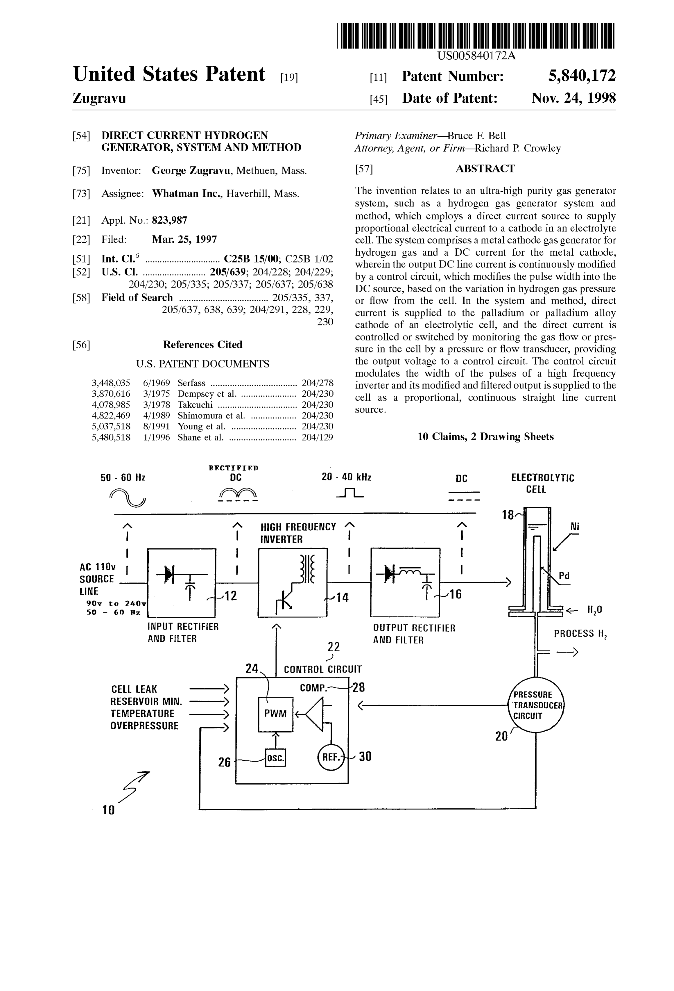
United States Patent (19) 11 Patent Number: 5,840,172 Zugravu (45) Date of Patent: Nov. 24, 1998 54) DIRECT CURRENT HYDROGEN Primary Examiner Bruce F. Bell GENERATOR, SYSTEM AND METHOD Attorney, Agent, or Firm-Richard P. Crowley 75 Inventor: George Zugravu, Methuen, Mass. 57 ABSTRACT 73 Assignee: Whatman Inc., Haverhill, Mass. The invention relates to an ultra-high purity gas generator System, Such as a hydrogen gas generator System and 21 Appl. No.: 823,987 method, which employs a direct current Source to Supply proportional electrical current to a cathode in an electrolyte 22 Filed: Mar. 25, 1997 cell. The System comprises a metal cathode gas generator for 6 hydrogen gas and a DC current for the metal cathode s 51 Int. Cl. ............................... 5 15700; C25B 1.02 wherein the output DC line current is continuously modified 52) U.S. Cl. ......... - - - - - - - - - - - - - - - - 20569; 2022820,229 by a control circuit, which modifies the pulse width into the 204/230; 205/335; 205/337; 205/637; 205/638 DC Source, based on the variation in hydrogen gas preSSure 58 Field of Search ..................................... 205/335, 337, or flow from the cell. In the system and method, direct 205/637, 638, 639; 204/291, 228, 229, current is Supplied to the palladium or palladium alloy 230 cathode of an electrolytic cell, and the direct current is controlled or Switched by monitoring the gas flow or pres 56) References Cited Sure in the cell by a pressure or flow transducer, providing
modulates the width of the pulses of a high frequency 3,448,035 6/1969 Serfass .................................... 204/278 inverter and its modified and filtered output is Supplied to the
cell as a proportional, continuous Straight line current 4,822,469 4/1989 Shimomura et al. ... 20230 source.
5,037,518 8/1991 Young et al. ........ ... 204/230 5,480,518 1/1996 Shane et al. ............................ 204/129 10 Claims, 2 Drawing Sheets
RFCTF)
50 - 60 Hz C 20 - 40 kHz DC ELECTROYC \, ?yy l CEll
HGH FREQUENCY MN
NVERTER /
SOURCE
LNE
NPUT RECFER MN OUTPUT RECTFER
AND FTER AND FILTER PROCESS H,
24 CONTROL CRCUIT
CEL LEAK -X PRESSURE RESERVOR MIN. --> RANSDCER EMPERATURE CIRCUIT
OWERPRESSURE
Page 2
Drawing sheet — no readable text.
Page 3
Drawing sheet — no readable text.
Page 4
DIRECT CURRENT HYDROGEN a Selected high frequency output, e.g., 20 to 100 GENERATOR, SYSTEM AND METHOD kilohertz e.g., 20 to 40 kHz;
BACKGROUND OF THE INVENTION f) a DC output and rectifier means to provide Selected, continuous DC current to the cathode of said cell;
Ultra-high purity hydrogen (e.g., 99.999% pure), is pro g) control circuit means, which includes a pulse width duced by activating a palladium or palladium alloy cathode modulator, and wherein the control circuit means in an electrochemical cell to dissociate /water and provide a receives Said Voltage output from the transducer means, hydrogen proton (see U.S. Pat. No. 3,448,035 hereby incor controls the selected DC current to the cathode of Said porated by reference). In Such high purity generators, water cell in response to Said transducer Voltage output by is electrolyzed and hydronium ions are reduced at the varying the width of the electrical pulse signal Sent to palladium cathode tube and end up as hydrogen gas the high frequency inverter means, thereby efficiently (99.999% pure) on the inside of the palladium tube. By adjusting the direct current to the cathode of the cell monitoring the generator output, gas flow or pressure; and responsive to the gas flow rate or preSSure. adjusting the energy Supplied to the electrolysis cell by an The System and method provides an improved economic AC power Source, the hydrogen output preSSure, and implic 15 cell generator, Since the Selected continuous DC current itly the output flow rate of the hydrogen, is controlled. power curve Supplied to the cell in the System permits a Other methods of producing hydrogen employ a Solid Smaller cathode tube, e.g. /s" in diameter, rather than /4" in polymer electrolyte in an ion exchange process, or an ion diameter, to be used to provide more effective cell Surface exchange membrane to produce oxygen-hydrogen (see U.S. area in the same cell Volume and to use leSS expensive Pat. No. 5,037,518 and U.S. Pat. No. 5,480,518, both patents palladium metal.
hereby incorporated by reference). However, these pro While the closed loop DC continuous system and method ceSSes do not produce ultra-high purity hydrogen in a Single is described in connection with the particular embodiment of Step, Since the hydrogen is produced with water vapor, the production of ultra-high purity hydrogen in an electro which must be removed, typically, in a downstream purifier lytic cell, Such System and method may be usefully used in containing Silica gel or a palladium membrane. 25 connection with the production of other hydrogen
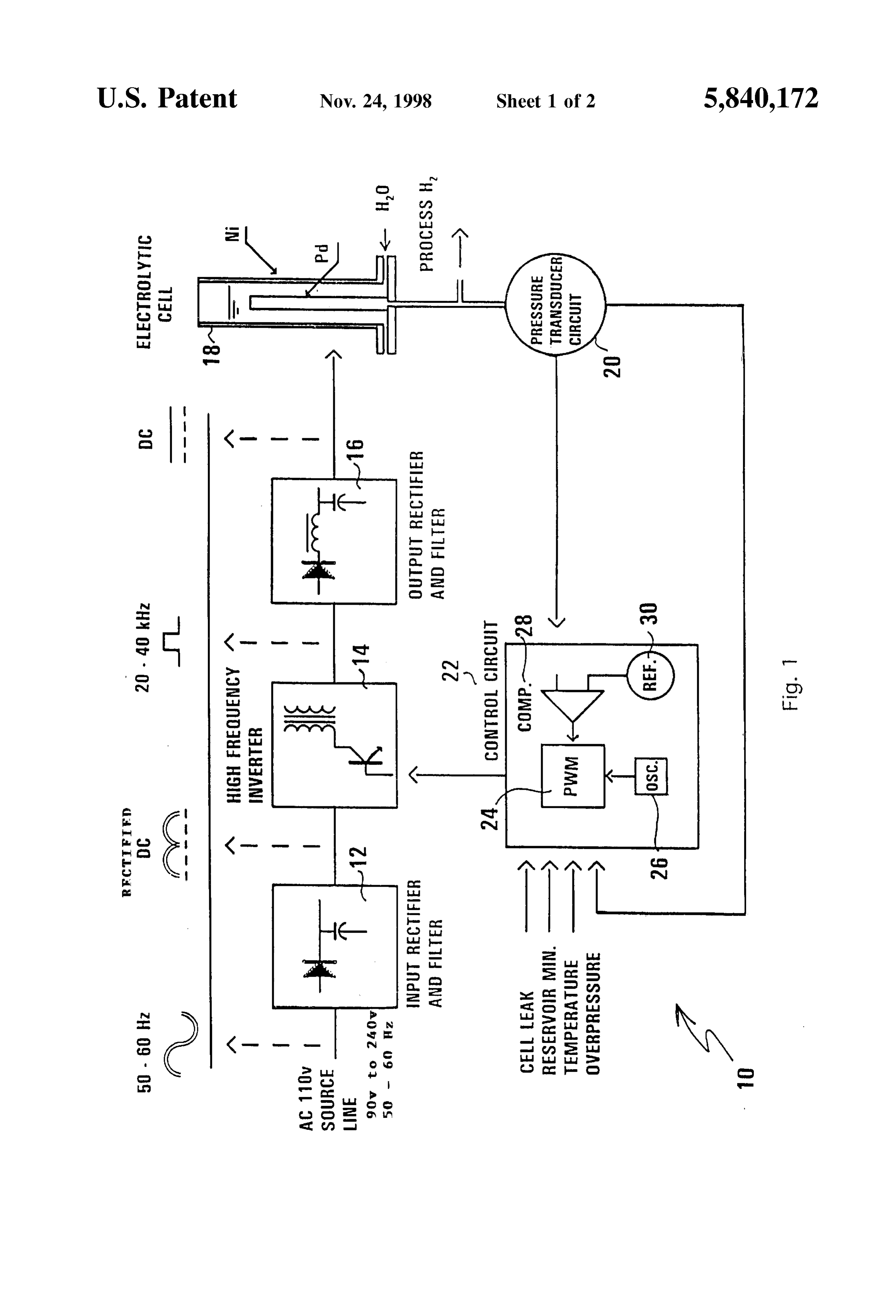
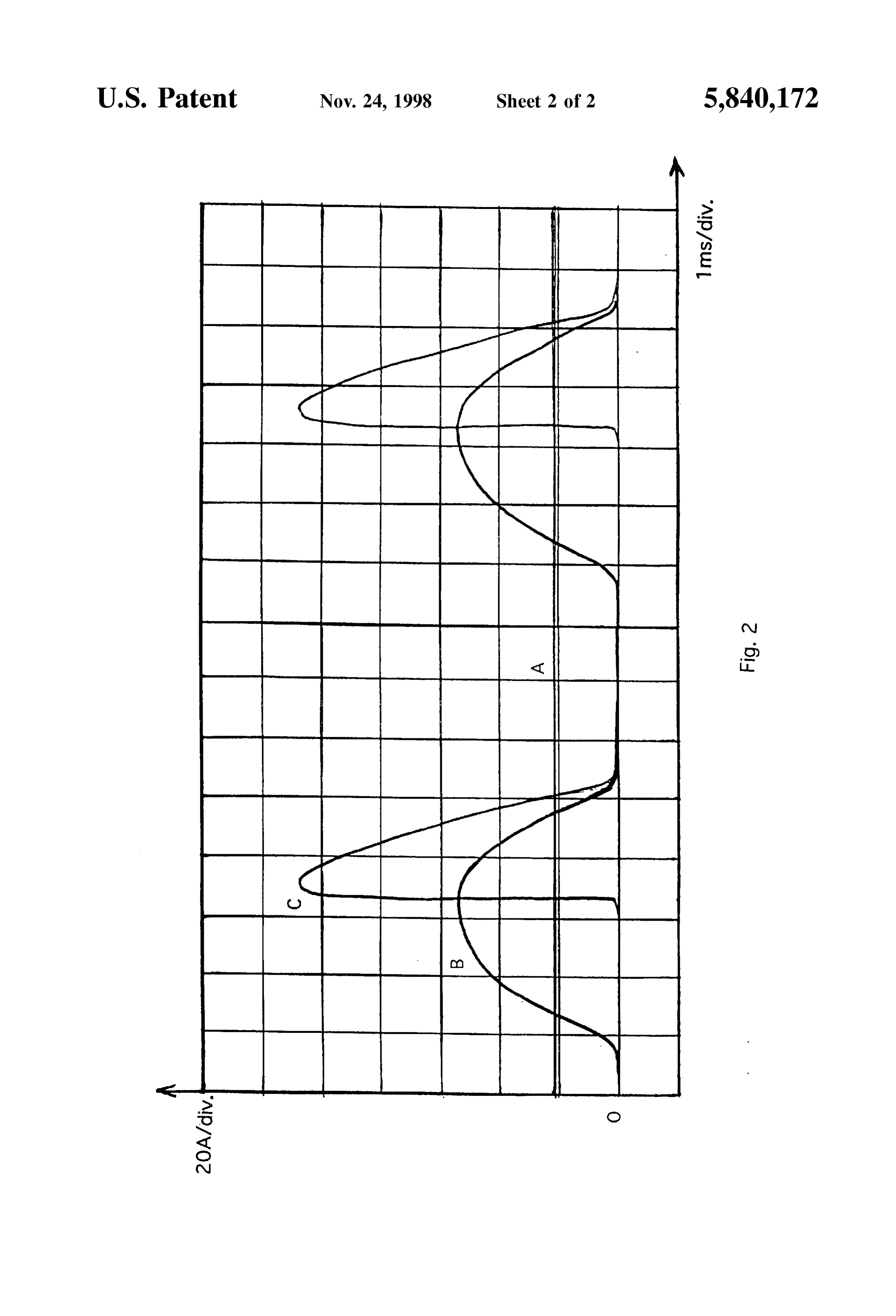
It is desirable to provide for a new and improved, Single generators, Such as Solid polymer electrolyte generators, and Step, closed loop gas generator System, Such as a hydrogen other electrically generated gas generators. electrolytic cell generator System and method, with increased hydrogen purity and efficiency. BRIEF DESCRIPTION OF THE DRAWINGS SUMMARY OF THE INVENTION FIG. 1 is a schematic illustrative block diagram of the The invention relates to an ultra-high purity gas generator System of the invention; and
System, Such as a hydrogen gas generator System and FIG. 2 is a graphical representation of electrical wave method, which employs a direct current Source to Supply function of current, in amps per division VS. time in milli proportional electrical current to a cathode in an electrolytic 35 Seconds per division, showing AC prior art current output (B cell. and C) in comparison to the invention (A). The System comprises a metal cathode gas generator for DESCRIPTION OF THE EMBODIMENTS hydrogen gas and a DC current Supply for the metal cathode, wherein the output DC line current is continuously modified 40 The system 10 of the invention is shown in the drawing by a control circuit, which modifies the pulse width into the of FIG.1. The system 10 comprises an AC input rectifier and DC Source based on the variation in hydrogen gas preSSure filter 12 to convert the 50 to 60 Hz, 90 v to 240 V AC power or flow from the cell. Supply from the Source line into a rectified DC output to a In the System and method, direct current is Supplied to the 40 to 100 kHz high frequency inverter 14, which reduces the palladium or palladium alloy cathode of an electrolytic cell, 45 rectified direct current output, with the pulse width modu and the direct current is controlled or Switched by monitor lation (PWM) output level required by the user's circuitry to ing the gas flow or pressure in the cell by a preSSure or flow a DC output rectifier and filter 16, wherein continuous direct transducer, and providing the output Voltage to a control current is supplied to an electrolytic cell 18. The cell 18 circuit. The control circuit modulates the width of the pulses having a metal nickel housing, and having a plurality of of a high frequency inverter, and its modified and filtered 50 palladium cathode tubes, and Supplied with electrolyte, to output is Supplied to the cell as a continuous Straight line provide a very high purity hydrogen gas. The System Current SOurce. includes a preSSure transducer 20 to monitor the hydrogen The invention comprises a System, which comprises: gas pressure output of the cell 18 and to provide a propor a) a high purity gas, e.g. hydrogen producing, Water tional output signal, e.g. Voltage, to a control circuit 22 with dissociating electrolytic cell, which includes a gas 55 an electrical Signal output into the high frequency inverter producing cathode, Such as palladium or an alloy to 14.
which direct current electrical power is Supplied, the The control circuit 22 closes the loop with its signal cell having an outlet to recover ultra-high purity gas, output into the inverter 14. The control circuit 22 includes a Such as hydrogen; pulse width modulator 24 (PWM), an oscillator 26, a voltage b) a pressure or flow transducer means to monitor the 60 comparator 28 and a reference 30. The control circuit 22 hydrogen gas pressure or flow of the cell, and to Supply regulates the Selected high frequency inverter DC output to a proportional Voltage pressure or flow rate output; the cell 18 and closes the electrical loop from the output of c) an AC power Source to Supply AC power; the inverter 14.
d) an AC input rectifier and filter means to rectify and The control circuit 22 generates a Selected fixed frequency filter the AC current of the AC Source to DC current; 65 internally, e.g. 40-100 kHz, and uses the PWM to imple e) a high frequency inverter means to convert the DC ment the desired DC output. The on-time of the square drive current from the AC input rectifier and filter means to output of the inverter 14 is controlled by the gas process out
Page 5
Voltage as a preSSure or flow function for the transducer 20. 2. The System of claim 1 wherein the gas generator As the input voltage (flow, pressure) to the control circuit 22 comprises a water-dissociable palladium cathode gas gen increases, a slight rise in input Voltage into the control circuit erator for the production of ultra-high purity hydrogen. 22 will signal the control circuit, by the PWM, to deliver 3. The System of claim 2 wherein the gas generator narrower pulses in the control circuit 22 output to the includes a cathode tube having a diameter of about one inverter 14, and conversely, as the input voltage (flow, eighth (/s) inch.
pressure) from the transducer 20 decreases, wider pulses will 4. The System of claim 1 wherein the gas generator be fed into the inverter 14 to modify the DC output current comprises a Solid polymer electrolyte for the production of to cell 18. Generally, the pulse duration will range from hydrogen.
about 10 to 25 microseconds (us). The system also shows 5. The system of claim 1 wherein the high frequency optionally that the control circuit 22 may monitor and inverter control other auxiliary functions of the cell 18 with either 20 to 100converts the DC power to a high frequency of about kilohertz DC power output.
power as desired, Such as cell leakage, the water use 6. The system of claim 1 wherein the modified pulse width reservoir of cell, the cell temperature and cell overpreSSure.
FIG. 2 shows a comparison between the current variation output has a pulse time of about 10 to 25 microSeconds. 7. An ultra-high purity hydrogen gas generator closed in amps per division versus time in milliseconds inclusion of 15 loop System, which System comprises: a prior art, commonly used “phase angle” (Curve C) or “amplitude, adjustable rectified DC” (Curve B) power con a) a hydrogen gas generator cell having an outlet for the troller for hydrogen cathode cell generators. The intervals of withdrawal of a high purity hydrogen gas generated by on-current alternate with intervals of no current and the ratio the application of a direct current to a water electrolyte of off/on can be as low as 2. This prior art operation results from a palladium cathode in the gas generator cell; in a high effective current value that needs to be Supplied to b) a transducer means in communication with Said outlet the cell. For a given hydrogen gas flow rate, this current to monitor the gas pressure or gas flow of the hydrogen value is twice as much as the current value from the direct gas from the outlet and to provide a proportional current power Supply System of the invention (see FIG. 2A) 25 electrical signal;
where the current line is Substantially continuous. The prior c) a 90 V to 240 V, 50 to 60 Hz AC power source to art method and systems (FIGS. 2B and C) provide higher provide AC current;
cell temperatures, with large intervals of no cathode oxida d) an AC input rectifier and filter means to rectify and tion reaction and mechanical StreSS on the cell.
filter the AC current from the AC Source to rectified DC
From the flow rate perspective, the continuous direct current, current Surge driven System with the cathode electrolytic cell doubles the hydrogen gas flow rate with no electromechani e) a high frequency inverter means to receive said recti fied DC current and to convert the rectified DC current cal StreSS forces applied to the cathode palladium tubes, to a Selected high frequency output to an output rectifier provides lower running cell temperature, and complete elimination of those time intervals when the reverse cathode and filter;
35 f) a DC output and rectifier means to Supply high reaction takes place.
What is claimed is: frequency, continuous, flat-modified DC power to the 1. A gas generator System for the generation of a Selected gas generator cell; and gas, by the application of an electrical direct current to an g) a control circuit means to include a pulse width electrolyte in a gas generator cell, which System comprises: 40 modulator to receive Said proportional Signal from the a) an input rectifier and filter to receive 50 to 60 Hz AC transducer and to provide a varied pulse width to the power and to rectify and filter from AC power to a DC high frequency inverter means Solely responsive to Said power output; proportional Signal and thereby to control the DC b) a high frequency inverter to receive the DC power power Supplied to the gas generator cell. output and provide a high frequency DC power output; 45 8. A method of providing a high purity gas from a DC c) a DC output and rectifier to receive the high frequency electrically powered gas generator having an electrolyte and DC power output and to provide a continuous DC a gas outlet for the withdrawal of the high purity gas, which power to a cathode of a gas generator; method comprises:
d) a gas generator with a cathode and having an a) providing a Source of AC power; electrolyte, which cell receives the continuous output 50 b) rectifying the AC power to a DC power outlet; DC power and provides for the generation of a high c) inverting the DC power output to provide a high purity gas from a generator output; frequency DC power output;
e) a transducer to monitor the gas pressure or gas flow d) monitoring the gas outlet for gas pressure or gas flow from the gas generator and to produce an electrical and producing a Voltage signal responsive to Such gas Voltage signal; and 55 preSSure or gas flow;
f) a control circuit which includes: e) comparing the Voltage signal to a reference signal to i) a voltage comparison circuit and reference circuit to produce a Voltage control Signal; receive and compare the Voltage Signal and to pro vide a Voltage control Signal; and f) generating a pulse width modulation signal from a pulse ii) a pulse width modulator (PWM) to receive the 60 width modulator and modifying the pulse width solely control signal and to provide an PWM output signal in response to the Voltage control Signal to provide a responsive to the control signal, which PWM signal PWM output signal;
feedsback to the high frequency inverter to modify g) modifying the high frequency DC power output by the the pulse width of the high frequency DC power PWM output signal to provide a high frequency PWM output to the DC output and rectifier to provide a 65 power output;
controlled, pulse-modified, continuous DC power to h) rectifying the PWM power output to provide a flat, the cathode of the gas generator. continuous DC power output; and
Page 6
S 6 i) providing the flat, continuous DC power output to the 10. The method of claim 8 which comprises providing the gas generator. DC power outlet to an ultra-high purity hydrogen gas 9. The method of claim 8 which includes providing AC generator with a palladium cathode. power to about 50 to 60 Hertz and increasing the frequency by inverting to a high frequency of about 20 to 100 kilohertz. k . . . .

Provenance
- Collection
- Cited prior art
- Original PDF
- patentimages.storage.googleapis.com →
- Filed
- 1997-03-25
- Pages
- 6
- Method
- pdftotext (the PDF's own text layer) + pdftoppm 300dpi page scans
- Source
- Google Patents bibliographic record
- Granted
- 1998-11-24
- Inventors
- George Zugravu; Whatman Inc
- Transcribed from
- patentimages.storage.googleapis.com →