patent · US3228863
Electrolytic process and apparatus for removing stock from a conductive workpiece
11 January 1966
Page 1
Drawing sheet — no readable text.
Page 2
Drawing sheet — no readable text.
Page 3
United States Patent Office 3,228,863 Patiented Jan. 11, 1966
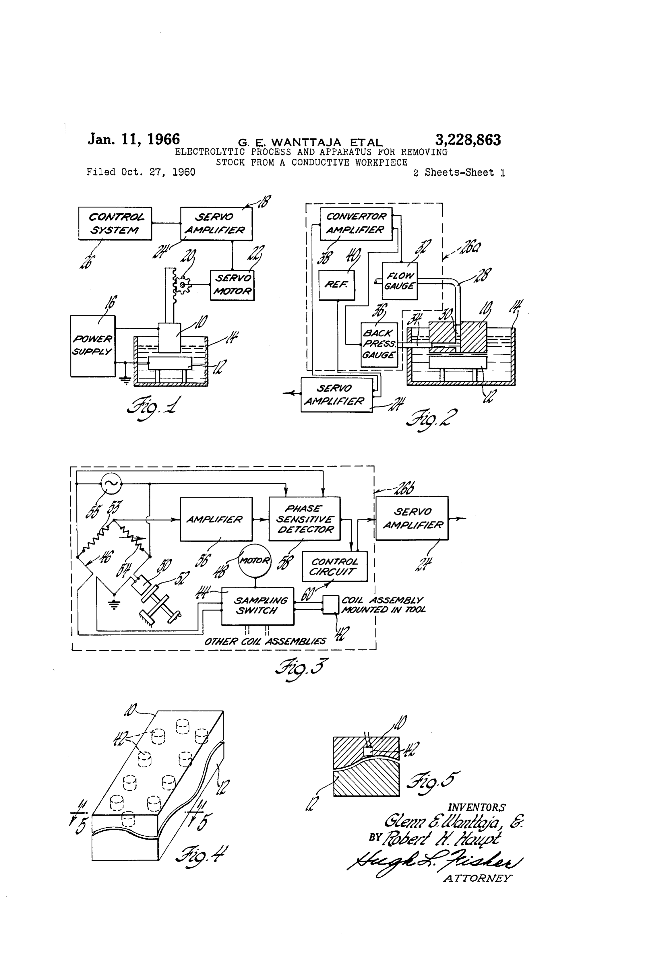
FIGURE 5 is a sectional view of FIGURE 4 taken
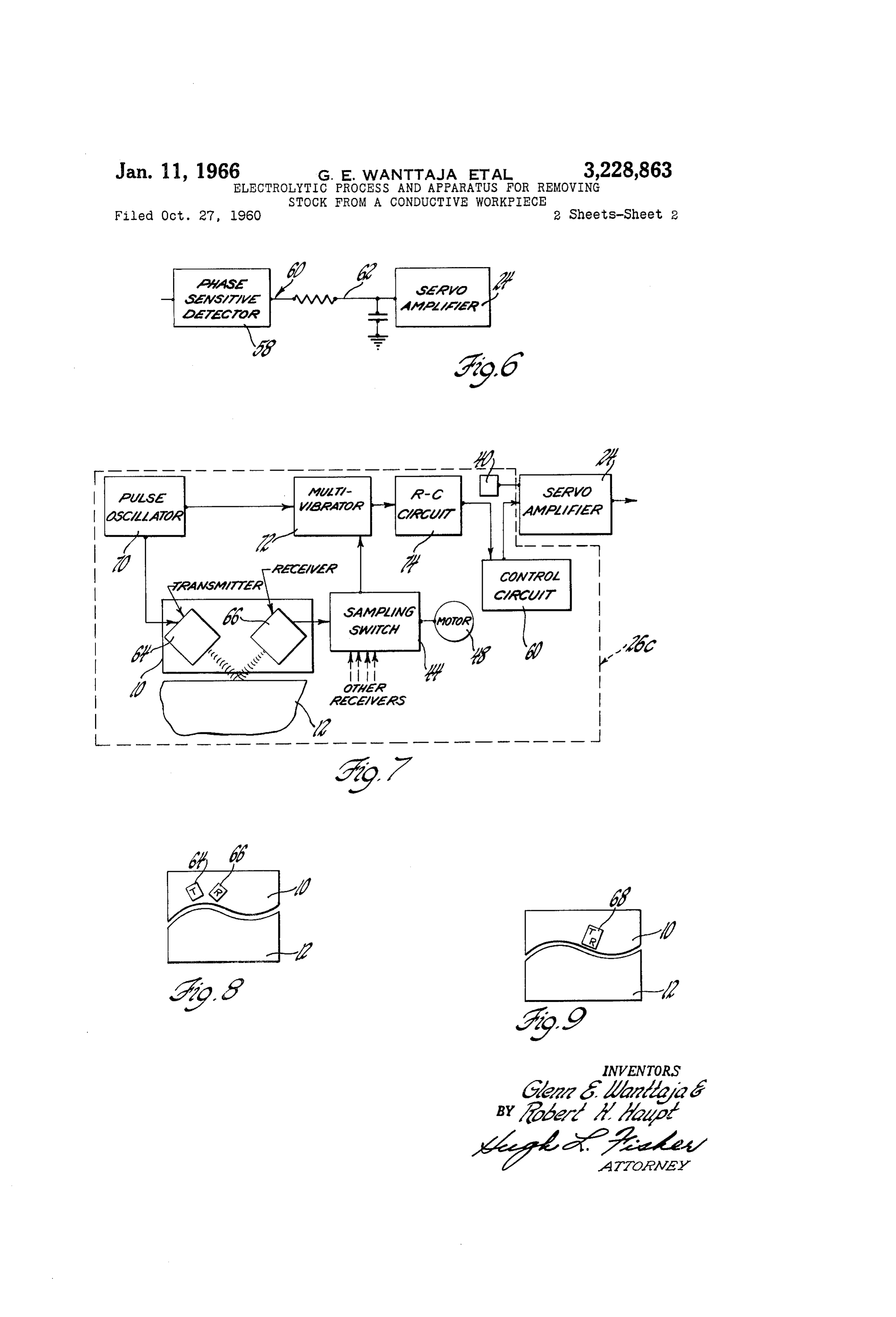
ELECTROLYTEC PROCESS AND APPARATUS FOR FIGURE 6 is a schematic diagram of a control circuit REMOWING STOCK FEROM A CONDUCTIVE that may be employed in the FIGURE 3 system; WORKPIECE FIGURE 7 is a block diagram of still another control lenn E. Waattaja, Hales Corners, Wis., and Robert H. System that may be utilized with the FIGURE 1 ap Haupt, Roseville, Mich., assignors to General Motors paratus; and
Corporation, Detroit, Mich., a corporation of Delaware FIGURES 8 and 9 show fragmentary sectional views Filed Oct. 27, 1960, Ser. No. 65,398 of the tool and workpiece electrodes and the arrange
10 ment thereof used in the FIGURE 7 control system.
This invention relates generally to stock removal ap Considering the drawings in detail, and initially FIG paratus and particularly to control systems adapted for URE 1, the numerals 10 and 12 designate electrodes for use, although not exclusively, with electrolytic stock re the apparatus and will hereinafter be referred to, respec moval apparatus. tively, as the tool and the workpiece. The tool 10 is In the process of electrically removing stock from a positioned opposite the workpiece 12 so that a predeter conductive workpiece electrode, there is always concern mined gap is established therebetween. The workpiece about the attainment of a satisfactory automatic feed 12 is situated in, and insulated from, a tank 14 contain of the tool and workpiece electrodes relative to each ing a suitable electrolyte of a quantity adequate to cause other. This problem becomes even more complicated the removal of stock from the workpiece 2 by chemical when an electrolyte is flowed through the gap between action. This stock removal process is accelerated by the electrodes, for if a constant feed rate is established, connecting a suitable power supply 16 across the gap varying conditions including changes in the electrolyte formed between the tool 10 and the workpiece 12 in a require periodic resetting of the gap. This, of course, manner such that the tool 10 becomes the cathode and demands operator attention and results in "down time” the workpiece 12, the grounded anode. The gap is opti or a non-productive interval. On the other hand, and mum for existing conditions and the results desired, i.e., again when an electrolyte is being employed, the use of workpiece finish and stock removal rates. gap Voltage as an indication of the gap spacing, and As the stock removal takes place by this method, com therefore offering a mode of automatically adjusting the monly referred to as the electrochemical machining feed rate with changing conditions, is not a satisfactory process, it is necessary, because the gap spacing will in Solution because when an electrolyte is employed, cur crease, to maneuver the tool 10 and the workpiece 12 rent density is greatest at the closest point between the together, if the optimum gap is to be maintained. This electrodes; whereas, a measurement of the gap voltage is accomplished by a maneuvering provision as the feed only produces an average voltage and does not inform mechanism. 18. In this instance, the feed mechanism 8 the operator of the close proximity of the electrodes at through gearing 20 in turn operated by a servomotor 22 this one point. As a consequence, the presence of this 3. 5 moves the tool 10 up and down relative to the workpiece high current density will produce overheating, which in 12. Of course, if preferred, the workpiece 12 can be turn can damage the adjacent areas of both the tool and moved and instead of gearing 20 and servomotor 22, the workpiece electrodes. a piston type motor can be combined directly with the With the foregoing problem in mind, the invention 40 electrode to be maneuvered. Or, both the electrodes can contemplates in the electrical stock removal process a be moved if necessary for effective use of the apparatus. unique mode of accurately controlling the feed rate be The servomotor 22 in this embodiment receives signals tween the electrodes so as to automatically maintain a via a servo amplifier 24 from a control System 26, which predetermined gap despite varying influencing conditions signals cause the servomotor 22 to increase or decrease and without operator attention. Moreover, by the in the feed rate as required to maintain this predetermined vention and in a novel fashion, variations in the gap optimum gap.
spacing from a predetermined gap are constantly sensed As has been stated, the feed rate can be constant. How and appropriate corrections are automatically made SO ever, there are many factors both internal and external as to maintain a predetermined gap between the elec that require from time to time that the gap spacing be trodes at all times. reset if a constant feed rate is utilized. For this reason, 50 a control system such as that shown in FIGURE 2 and
In carrying out the foregoing, the invention as another aim thereof seeks to provide various ways of measuring denoted generally by the numeral 26a is preferably uti the gap spacing including ascertaining the time interval lized. In system 26a, an electrolyte supply conduit 28 is required to transfer energy between the electrodes, deter connected to an orifice 30 in the tool 10 and includes mining variations in a magnetic link between the elec therein a flow gage 32 that establishes the rate of flow of trodes due to their proximity, measuring differences, 5 5 the incoming electrolyte. Also associated with the con again due to the proximity of the electrodes, in the im duit 28 is a branch 34 arranged to interconnect the ori pedance of an energizing circuit carried by one of the fice 30 with a back pressure gage 36. The gages 32 and electrodes, and determining variations in the pressure of 36 are of any known construction and develop alternating the fluid in the gap areas produced by deviations in the 60 signals determined by the condition of the electrolyte, i.e., gap spacing from a certain gap. flow and pressure. With this gage arrangement, as the The foregoing and other objectives and advantages of spacing between the tool 10 and workpiece 12 is varied, the invention will become apparent from the following the resultant back pressure will similarly change and de description and from the following drawings in which: velop a corresponding signal that will be delivered to the FIGURE 1 demonstrates apparatus utilized in demon input of a converter and amplifier 38. Also supplied to strating the principles of the invention; the input of the converter and amplifier 38 is a signal FIGURE 2 is a schematic showing of a control system from the flow gage 32, this signal affording a way of cor utilizable in the FIGURE 1 apparatus; relating flow with the back pressure since increased flow FIGURE 3 illustrates in a block diagram form another will similarly increase back pressure as will decreased flow control system for the FIGURE 1 apparatus; decrease back pressure. Of course, if flow is always con FIGURE 4 shows a view of tool and workpiece elec stant, the flow gage 32 will not be necessary. The varia trodes employed by the FIGURE 3 system; tions in the back pressure signal with a certain flow are
Page 4
converted to a D.C. control signal and amplified if re URE 6 where an integrating circuit 62 of a proper time quired prior to being transferred to the servo amplifier constant is displayed for obtaining this average of all the 24. If the gages 32 and 36 afford D.C. control signals, error signals. Preferably, if one of the coil assemblages of course the converter will not be needed. The servo 42 should indicate that the tool 10 at the checking point amplifier 24 has as a part thereof a reference voltage is dangerously close to the workpiece 12, the resultant source 40 and is so arranged that the control signal is error signal will cause the process to be stopped. This compared with the reference signal by suitable summing can be accomplished in any appropriate way. For ex circuitry so as to develop an output or error signal for ample, the error signal produced when this condition use by the servomotor 22 indicating both the direction of exists can cause interruption of the operation of the in movement and distance needed to maneuver the tool 0 in tegrating circuit 62 as well as cause the power supply 16 order to establish the desired gap spacing. For instance, IO to be cut off.
if the error signal furnished to the servomotor 22 is nega With the FIGURE 3 control system, both magnetic tive, the servomotor 22 can be caused to increase the feed and non-magnetic conductive workpieces can be machined. rate of the tool 10; whereas, if the control signal is posi If the workpiece 12 is magnetic, the spacing between the tive, the tool 10 can be withdrawn, in each instance until coil assemblages 42 and the workpiece 12 will vary the a null error signal is obtained. magnetic link or coupling therebetween and accordingly Another control system, assigned the numeral 26b, is change the impedance in the arm of the bridge 46 to displayed in FIGURE 3. This system utilizes one or which the coil assemblages 42 are connected. In this more transducers, such as inductors or coil assemblages instance this will be a change in the inductance, which 42, each of which is positioned within the tool 10 as 20 inductance will increase as the tool 10 and the workpiece demonstrated in FIGURES 4 and 5. The number of 12 are moved closer together. On the other hand, if the these assemblages 42 will depend upon the size and con workpiece 12 is non-magnetic, the alternating current tour of the tool 10 and the workpiece 12. If a number of source 55 will, through the coil assemblages 42, induce coil assemblages 42 are required, then a sampling switch eddy current activity in the non-magnetic workpiece 12. as that denoted by the numeral 44 may be employed for 25 The eddy current intensity will increase as the spacing be sequentially or selectively connecting the individual coil tween the tool 10 and the workpiece 12 is decreased and assemblages 42 to a bridge shown at 46. The sampling again this variation in the eddy current intensity will in switch 44 can be operated mechanically and/or electrical fluence the impedance of the coil assemblages 42 by low ly, e.g., by a motor 48 so that each coil assemblage is in ering the apparent resistance thereof when the gap spac dividually connected to the one arm of the bridge 46 for 30 ing is decreased.
a certain interval. Another arm of the bridge 46 affords The other control system that may be utilized by the a reference and includes a reference coil assemblage 50 FIGURE 1 apparatus is depicted in FIGURE 7 and is that is positioned opposite a reference workpiece 52. The assigned the numeral 26c. In this system, the tool 10 has space between the reference coil assemblage 50 and the Suitably incorporated therein separate sending and receiv reference workpiece 52 can be altered as desired so as to ing transducers 64 and 66 as viewed in FIGURE 8 or a establish the gap spacing at which the stock removal proc combined sending and receiving transducer 68 as seen in ess is to be conducted. Also, it should be kept in mind FIGURE 9. For explanatory purposes only, the trans that the reference workpiece 52 should have the same ducers 64 and 66 will be described since combined trans magnetic and conductive characteristics as the workpiece ducer 68 will perform in substantially the same way. 12. The other arms of the bridge 46 include impedances 40 Transducers 64 and 66 are arranged as seen in FIGURE 7 53 and 54, impedance 54 being adjustable for calibration So that the sending transducer 64 is connected to the out purposes. put of a pulse oscillator 70. The same pulse oscillaltor If the spacing of the coil assemblages 42 relative to the 70 has another output thereof connected to a flip-flop type workpiece 12 corresponds to that of the reference coil multivibrator 72, which functions as a switch. Preferably, assemblage 50 and the reference workpiece 52, and fur the pulse oscillator 70 generates ultrasonic frequencies so ther assuming that the input of the bridge 46 is connected 45 that when a pulse signal is produced, it is sent simultane to an alternating current source 55, there will be a null ously to the multivibrator turning it on, and to the send output signal since the bridge 46 will be balanced. But, ing transducer 64. The sending transducer 64 will emit if there is a discrepancy, an unbalanced voltage of a phase the pulse signal toward the surface of the workpiece 12 determined by the proximity of the tool 10 and the work from which it will be reflected due to the arrangement of piece 12, i.e., whether the gap spacing is less or greater the transducers and picked up by the receiving transducer than that predetermined, will be developed, which volt 66. The reflected pulse signal then is delivered to the age may be increased by an amplifier 56 if needed and multivibrator 72 via the sampling switch 44, if several then supplied to the input of a phase sensitive detector 58. sets of these transducers 64 and 66 or the combination At this point, a D.C. error signal will be developed hav transducer 68 are required due to the types of workpiece ing a polarity and magnitude corresponding to the amount 5 5 12 being machined. The reflected pulse signal will turn of difference between the actual gap spacing and the de the multivibrator 72 off. As is now apparent, if the two sired gap spacing and whether the actual spacing is too pulses generated simultaneously by the oscillator 70 are close or too far way. Again, it can be assumed if too delivered to the multivibrator simultaneously, the pulse close the polarity of this error signal will be positive; signal turning the multivibrator 72 on will be counter whereas, if too far apart, a negative error signal will be 60 acted by the pulse signal turning it off, and hence, the produced. Also, it should be noted that the operation of multivibrator 72 will not generate an output. But, be the assemblages 42 for gap spacing control purposes is cause of the time delay induced due to the distance be uninfluenced by the conditions of the electrolyte and the tween the tool 10 and the workpiece 12, the multivibrator machining current and voltage. 72 will be on for an interval corresponding to the gap The error signal, if only one coil assemblage is em spacing and during this interval develop a proportional ployed, may be supplied directly to the servo amplifier 24 output control signal. The control signal from the multi and then to the servomotor 22 in FIGURE 1 so as to cause vibrator 72 is preferably applied to an R.C. circuit 74 so the appropriate correction to be made in the manner ex as to obtain an average D.C. control signal and thereafter plained with respect to the FIGURE 2 control system. supplied directly to the servo amplifier 24 if only one set But, if there are a series of coil assemblages 42, the sam 70 of transducers is employed. If a series is employed, then pling switch 44 is utilized along with a control circuit as with the FIGURE 3 control system 26b, the control 60, and the average of the error signals from all of the circuit 60 may be employed to obtain an average of the coil assemblages 42 can be integrated to develop an aver control signals from all of the sets of transducers, which age error signal voltage for supplying to the servo ampli average will be supplied to the servo amplifier 24 and fier 24. One way of accomplishing this is shown in FIG compared with the reference voltage source 40 as in the
Page 5
FIGURE 2 system. The servo amplifier 24 will supply the workpiece electrode, generating an alternating mag the corresponding error signal to the servomotor 22 as netic field in the workpiece electrode from an energizing described in the explanation of the FIGURE 2 system. circuit carried by one of the electrodes, sensing impedance Also, in the event one set of transducers 64 and 66 in changes in the energizing circuit due to variations in the dicates that the tool is is too close to the workpiece 12 gap spacing from a predetermined gap at a plurality of at the area which the set of transducers 64 and 66 con points between the workpiece and the electrode, and al trols and as in the FIGURE 3 system, the process can be tering the maneuvering of the electrodes relative to each stopped. other in response to the impedance changes so as to main it should be mentioned that the FIGURE 2 system tain the predetermined gap.
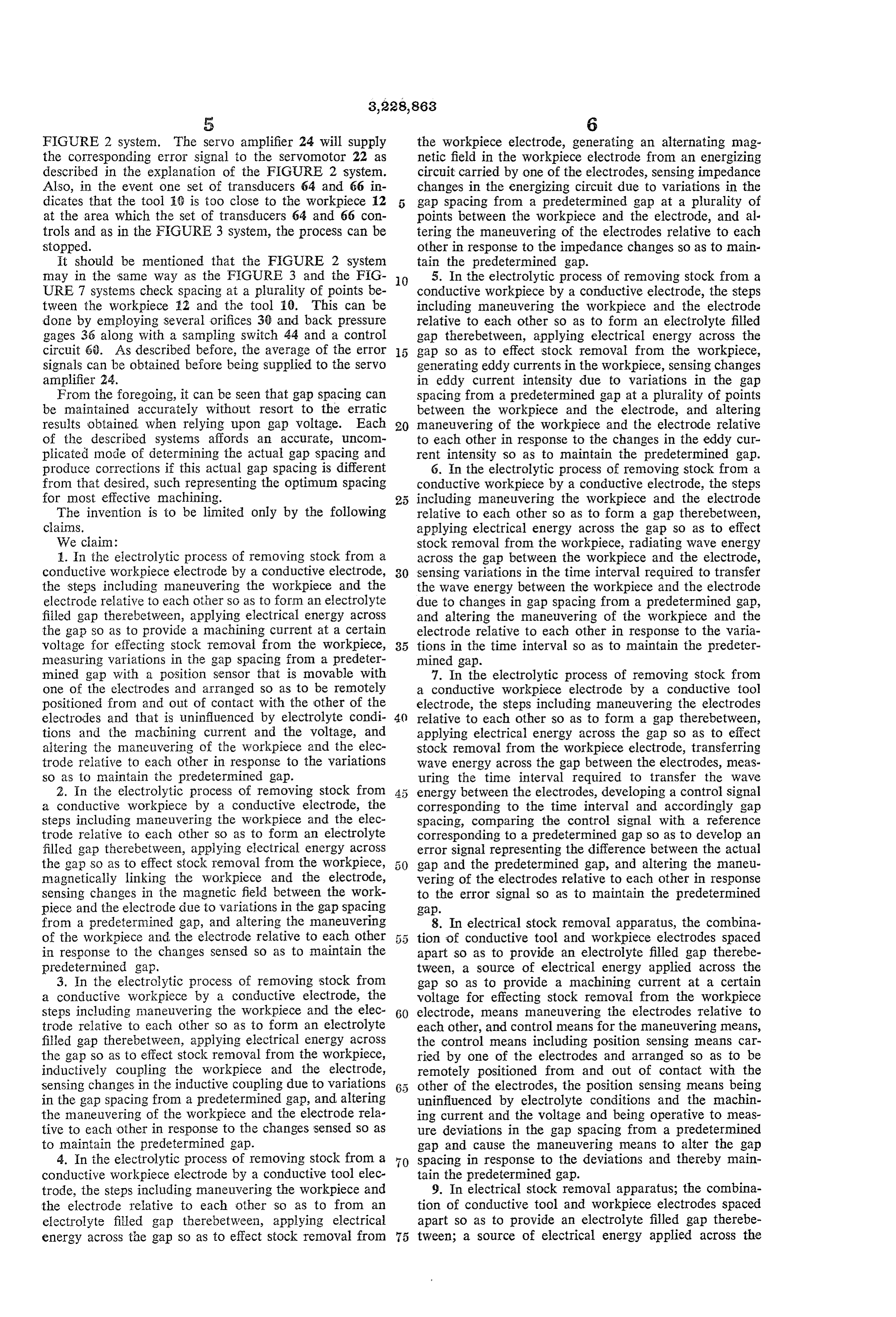
may in the same way as the FIGURE 3 and the FIG 5. In the electrolytic process of removing stock from a URE 7 systems check spacing at a plurality of points be O conductive workpiece by a conductive electrode, the steps tween the workpiece E2 and the tool 10. This can be including maneuvering the workpiece and the electrode done by employing several orifices 36 and back pressure relative to each other so as to form an electrolyte filled gages 36 along with a sampling Switch 44 and a control gap therebetween, applying electrical energy across the circuit 6). As described before, the average of the error gap so as to effect stock removal from the workpiece, signals can be obtained before being Supplied to the servo generating eddy currents in the workpiece, sensing changes amplifier 24. in eddy current intensity due to variations in the gap From the foregoing, it can be seen that gap spacing can spacing from a predetermined gap at a plurality of points be maintained accurately without resort to the erratic between the workpiece and the electrode, and altering results obtained when relying upon gap voltage. Each maneuvering of the workpiece and the electrode relative of the described systems affords an accurate, uncom to each other in response to the changes in the eddy cur plicated mode of determining the actual gap spacing and rent intensity so as to maintain the predetermined gap. produce corrections if this actual gap spacing is different 6. In the electrolytic process of removing stock from a from that desired, such representing the optimum spacing conductive workpiece by a conductive electrode, the steps for most effective machining. including maneuvering the workpiece and the electrode The invention is to be limited only by the following relative to each other so as to form a gap therebetween, claims. applying electrical energy across the gap so as to effect We ciain: stock removal from the workpiece, radiating Wave energy 1. In the electrolytic process of removing stock from a across the gap between the workpiece and the electrode, conductive workpiece electrode by a conductive electrode, 30 Sensing variations in the time interval required to transfer the steps including maneuvering the workpiece and the the wave energy between the workpiece and the electrode electrode relative to each other so as to form an electrolyte due to changes in gap spacing from a predetermined gap, filed gap therebetween, applying electrical energy across and altering the maneuvering of the workpiece and the the gap so as to provide a machining current at a certain electrode relative to each other in response to the varia voltage for effecting stock removal from the workpiece, 35 tions in the time interval so as to maintain the predeter measuring variations in the gap spacing from a predeter mined gap.
mined gap with a position sensor that is movable with 7. In the electrolytic process of removing stock from one of the electrodes and arranged so as to be remotely a conductive workpiece electrode by a conductive tool positioned from and out of contact with the other of the electrode, the steps including maneuvering the electrodes electrodes and that is uninfluenced by electrolyte condi 40 relative to each other so as to form a gap therebetween, tions and the machining current and the voltage, and applying electrical energy across the gap so as to effect altering the maneuvering of the workpiece and the elec stock removal from the workpiece electrode, transferring trode relative to each other in response to the variations wave energy across the gap between the electrodes, meas so as to maintain the predetermined gap. uring the time interval required to transfer the wave 2. In the electrolytic process of removing stock from energy between the electrodes, developing a control signal a conductive workpiece by a conductive electrode, the corresponding to the time interval and accordingly gap steps including maneuvering the workpiece and the elec spacing, comparing the control signal with a reference trode relative to each other so as to form an electrolyte corresponding to a predetermined gap so as to develop an filled gap therebetween, applying electrical energy across error signal representing the difference between the actual the gap so as to effect stock removal from the Workpiece, gap and the predetermined gap, and altering the maneu magnetically linking the workpiece and the electrode, vering of the electrodes relative to each other in response sensing changes in the magnetic field between the work to the error signal so as to maintain the predetermined piece and the electrode due to variations in the gap Spacing gap.
from a predetermined gap, and altering the maneuvering 8. In electrical stock removal apparatus, the combina of the workpiece and the electrode relative to each other 55 tion of conductive tool and workpiece electrodes spaced in response to the changes sensed so as to maintain the apart so as to provide an electrolyte filled gap therebe predetermined gap, tween, a source of electrical energy applied across the 3. In the electrolytic process of removing stock from gap so as to provide a machining current at a certain a conductive workpiece by a conductive electrode, the voltage for effecting stock removal from the workpiece steps including maneuvering the workpiece and the elec 60 electrode, means maneuvering the electrodes relative to trode relative to each other so as to form an electrolyte each other, and control means for the maneuvering means, filled gap therebetween, applying electrical energy across the control means including position sensing means car the gap so as to effect stock removal from the workpiece, ried by one of the electrodes and arranged so as to be inductively coupling the workpiece and the electrode, remotely positioned from and out of contact with the sensing changes in the inductive coupling due to variations other of the electrodes, the position sensing means being in the gap spacing from a predetermined gap, and altering uninfluenced by electrolyte conditions and the machin the maneuvering of the workpiece and the electrode rela ing current and the voltage and being operative to meas tive to each other in response to the changes Sensed so as ure deviations in the gap spacing from a predetermined to maintain the predetermined gap. gap and cause the maneuvering means to alter the gap 4. In the electrolytic process of removing stock from a spacing in response to the deviations and thereby main conductive workpiece electrode by a conductive tool elec tain the predetermined gap.
trode, the steps including maneuvering the workpiece and 9. In electrical stock removal apparatus; the combina the electrode relative to each other so as to from an tion of conductive tool and workpiece electrodes spaced electrolyte filed gap therebetween, applying electrical apart so as to provide an electrolyte filled gap therebe energy across the gap so as to effect stock removal from 75 tween; a source of electrical energy applied across the
Page 6
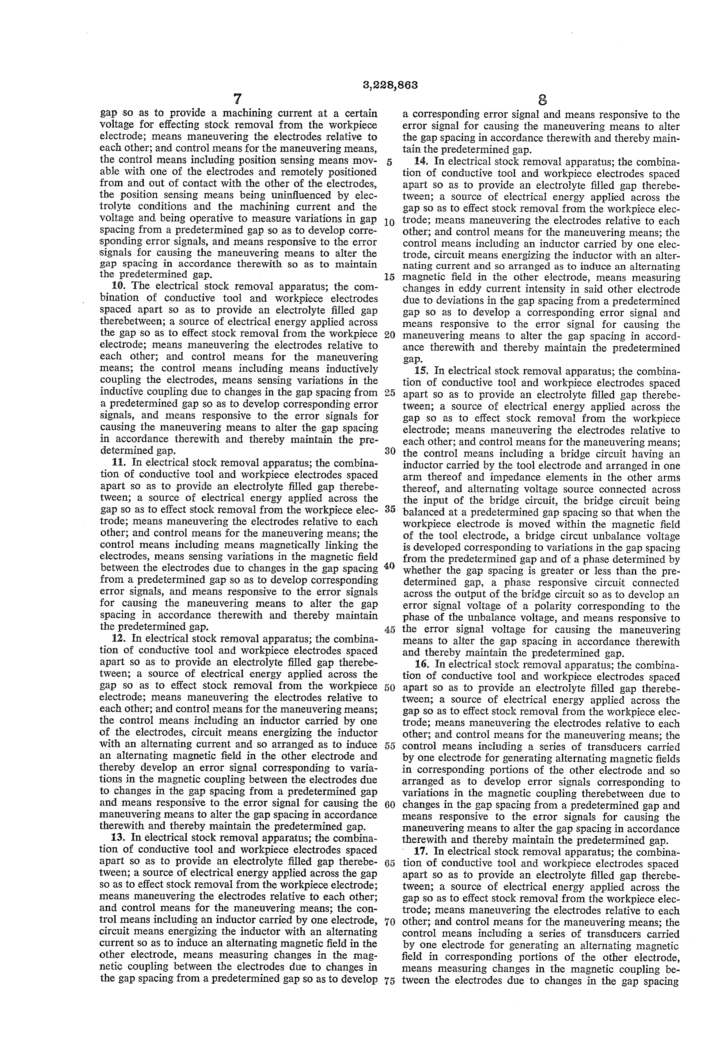
gap so as to provide a machining current at a certain a corresponding error signal and means responsive to the voltage for effecting stock removal from the workpiece error signal for causing the maneuvering means to alter electrode; means maneuvering the electrodes relative to the gap spacing in accordance therewith and thereby main each other; and control means for the maneuvering means, tain the predetermined gap.
the control means including position sensing means mov 14. In electrical stock removal apparatus; the combina able with one of the electrodes and remotely positioned tion of conductive tool and workpiece electrodes spaced from and out of contact with the other of the electrodes, apart so as to provide an electrolyte filled gap therebe the position sensing means being uninfluenced by elec tween; a source of electrical energy applied across the trolyte conditions and the machining current and the gap so as to effect stock removal from the workpiece elec voltage and being operative to measure variations in gap 10 trode; means maneuvering the electrodes relative to each spacing from a predetermined gap so as to develop corre other; and control means for the maneuvering means; the sponding error signals, and means responsive to the error control means including an inductor carried by one elec signals for causing the maneuvering means to alter the trode, circuit means energizing the inductor with an alter gap spacing in accordance therewith so as to maintain nating current and so arranged as to induce an alternating the predetermined gap. 5 magnetic field in the other electrode, means measuring 10. The electrical stock removal apparatus; the com changes in eddy current intensity in said other electrode bination of conductive tool and workpiece electrodes due to deviations in the gap spacing from a predetermined spaced apart so as to provide an electrolyte filled gap gap so as to develop a corresponding error signal and therebetween; a source of electrical energy applied across means responsive to the error signal for causing the the gap so as to effect stock removal from the workpiece 20 maneuvering means to alter the gap spacing in accord electrode; means maneuvering the electrodes relative to ance therewith and thereby maintain the predetermined each other; and control means for the maneuvering gap.
means; the control means including means inductively 15. In electrical stock removal apparatus; the combina coupling the electrodes, means sensing variations in the tion of conductive tool and workpiece electrodes spaced inductive coupling due to changes in the gap spacing from apart so as to provide an electrolyte filled gap therebe a predetermined gap so as to develop corresponding error tween; a source of electrical energy applied across the signals, and means responsive to the error signals for gap so as to effect stock removal from the workpiece causing the maneuvering means to alter the gap spacing electrode; means maneuvering the electrodes relative to in accordance therewith and thereby maintain the pre each other; and control means for the maneuvering means; determined gap. the control means including a bridge circuit having an 11. In electrical stock removal apparatus; the combina inductor carried by the tool electrode and arranged in one tion of conductive tool and workpiece electrodes spaced arm thereof and impedance elements in the other arms apart so as to provide an electrolyte filled gap therebe thereof, and alternating voltage source connected across tween; a source of electrical energy applied across the the input of the bridge circuit, the bridge circuit being gap so as to effect stock removal from the workpiece elec 35 balanced at a predetermined gap spacing so that when the trode; means maneuvering the electrodes relative to each workpiece electrode is moved within the magnetic field other; and control means for the maneuvering means; the of the tool electrode, a bridge circut unbalance voltage control means including means magnetically linking the is developed corresponding to variations in the gap spacing electrodes, means sensing variations in the magnetic field from the predetermined gap and of a phase determined by between the electrodes due to changes in the gap spacing 40 whether the gap spacing is greater or less than the pre from a predetermined gap so as to develop corresponding determined gap, a phase responsive circuit connected error signals, and means responsive to the error signals across the output of the bridge circuit so as to develop an for causing the maneuvering means to alter the gap error signal voltage of a polarity corresponding to the spacing in accordance therewith and thereby maintain phase of the unbalance voltage, and means responsive to the predetermined gap. 45 the error signal voltage for causing the maneuvering 12. In electrical stock removal apparatus; the combina means to alter the gap spacing in accordance therewith tion of conductive tool and workpiece electrodes spaced and thereby maintain the predetermined gap. apart so as to provide an electrolyte filled gap therebe 16. In electrical stock removal apparatus; the combina tween; a source of electrical energy applied across the tion of conductive tool and workpiece electrodes spaced gap so as to effect stock removal from the workpiece 50 apart so as to provide an electrolyte filled gap therebe electrode; means maneuvering the electrodes relative to tween; a source of electrical energy applied across the each other; and control means for the maneuvering means; gap so as to effect stock removal from the workpiece elec the control means including an inductor carried by one trode; means maneuvering the electrodes relative to each of the electrodes, circuit means energizing the inductor other; and control means for the maneuvering means; the with an alternating current and so arranged as to induce 55 control means including a series of transducers carried an alternating magnetic field in the other electrode and by one electrode for generating alternating magnetic fields thereby develop an error signal corresponding to varia in corresponding portions of the other electrode and so tions in the magnetic coupling between the electrodes due arranged as to develop error signals corresponding to to changes in the gap spacing from a predetermined gap variations in the magnetic coupling therebetween due to and means responsive to the error signal for causing the 60 changes in the gap spacing from a predetermined gap and maneuvering means to alter the gap spacing in accordance means responsive to the error signals for causing the therewith and thereby maintain the predetermined gap. maneuvering means to alter the gap spacing in accordance 13. In electrical stock removal apparatus; the combina therewith and thereby maintain the predetermined gap. tion of conductive tool and workpiece electrodes spaced 17. In electrical stock removal apparatus; the combina apart so as to provide an electrolyte filled gap therebe tion of conductive tool and workpiece electrodes spaced tween; a source of electrical energy applied across the gap apart so as to provide an electrolyte filled gap therebe so as to effect stock removal from the workpiece electrode; tween; a source of electrical energy applied across the means maneuvering the electrodes relative to each other; gap so as to effect stock removal from the workpiece elec and control means for the maneuvering means; the con trode; means maneuvering the electrodes relative to each trol means including an inductor carried by one electrode, 70 other; and control means for the maneuvering means; the circuit means energizing the inductor with an alternating control means including a series of transducers carried current so as to induce an alternating magnetic field in the by one electrode for generating an alternating magnetic other electrode, means measuring changes in the mag field in corresponding portions of the other electrode, netic coupling between the electrodes due to changes in means measuring changes in the magnetic coupling be the gap spacing from a predetermined gap So as to develop 75 tween the electrodes due to changes in the gap spacing
Page 7
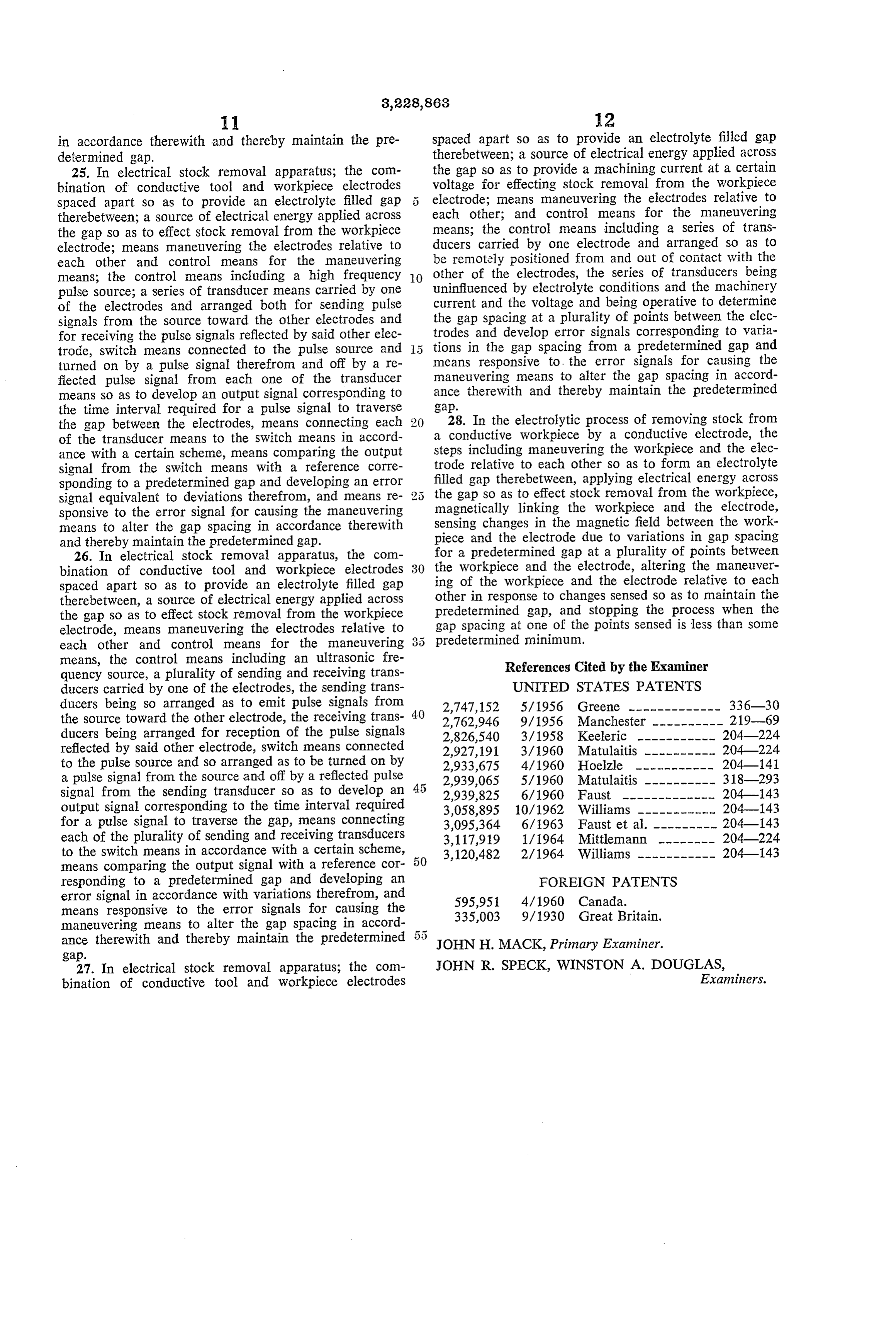
in accordance therewith and thereby maintain the pre spaced apart so as to provide an electrolyte filled gap determined gap. therebetween; a source of electrical energy applied across 25. In electrical stock removal apparatus; the com the gap so as to provide a machining current at a certain bination of conductive tool and workpiece electrodes voltage for effecting stock removal from the workpiece spaced apart so as to provide an electrolyte filled gap 5 electrode; means maneuvering the electrodes relative to therebetween; a source of electrical energy applied across each other; and control means for the maneuvering the gap so as to effect stock removal from the workpiece means; the control means including a series of trans electrode; means maneuvering the electrodes relative to ducers carried by one electrode and arranged so as to each other and control means for the maneuvering be remotely positioned from and out of contact with the means; the control means including a high frequency O other of the electrodes, the series of transducers being pulse source; a series of transducer means carried by one uninfluenced by electrolyte conditions and the machinery of the electrodes and arranged both for sending pulse current and the voltage and being operative to determine signals from the source toward the other electrodes and the gap spacing at a plurality of points between the elec for receiving the pulse signals reflected by said other elec trodes and develop error signals corresponding to varia trode, Switch means connected to the pulse source and tions in the gap spacing from a predetermined gap and turned on by a pulse signal therefrom and off by a re means responsive to... the error signals for causing the fiected pulse signal from each one of the transducer maneuvering means to alter the gap spacing in accord means so as to develop an output signal corresponding to ance therewith and thereby maintain the predetermined the time interval required for a pulse signal to traverse gap.
the gap between the electrodes, means connecting each ; 28. In the electrolytic process of removing stock from of the transducer means to the Switch means in accord a conductive workpiece by a conductive electrode, the ance with a certain scheme, means comparing the output steps including maneuvering the workpiece and the elec signal from the Switch means with a reference corre trode relative to each other so as to form an electrolyte sponding to a predetermined gap and developing an error filled gap therebetween, applying electrical energy across signal equivalent to deviations therefrom, and means re 2 5 the gap so as to effect stock removal from the workpiece, magnetically linking the workpiece and the electrode, sponsive to the error signal for causing the maneuvering means to alter the gap spacing in accordance therewith sensing changes in the magnetic field between the work and thereby maintain the predetermined gap. piece and the electrode due to variations in gap spacing 26. In electrical stock removal apparatus, the com for a predetermined gap at a plurality of points between bination of conductive tool and workpiece electrodes 30 the workpiece and the electrode, altering the maneuver spaced apart so as to provide an electrolyte filled gap ing of the workpiece and the electrode relative to each therebetween, a source of electrical energy applied across other in response to changes sensed so as to maintain the the gap so as to effect stock removal from the workpiece predetermined gap, and stopping the process when the electrode, means maneuvering the electrodes relative to gap spacing at one of the points sensed is less than some each other and control means for the maneuvering 3: 5 predetermined minimum.
means, the control means including an ultrasonic fre References Cited by the Examiner quency source, a plurality of sending and receiving trans ducers carried by one of the electrodes, the sending trans UNITED STATES PATENTS ducers being so arranged as to emit pulse signals from 2,747,152 5/1956 Greene ------------- 336-30 the source toward the other electrode, the receiving trans 40 2,762,946 9/1956 Manchester ---------- 21.9-69 ducers being arranged for reception of the pulse signals 2,826,540 3/1958 Keeleric ----------- 204-224 reflected by said other electrode, switch means connected 2,927,191 3/1960 Matulaitis ---------- 204-224 to the pulse source and so arranged as to be turned on by 2,933,675 4/1960 Hoelzle ---------- 204-141 a pulse signal from the source and off by a reflected pulse 2,939,065 5/1960 Matulaitis ---------- 318-293 signal from the sending transducer so as to develop an 2,939,825 6/1960 Faust ------------- 204-143 output signal corresponding to the time interval required 3,058,895 10/1962 Williams ------- 204-143 for a pulse signal to traverse the gap, means connecting 3,095,364 6/1963 Faust et al. ------- 204-143 each of the plurality of sending and receiving transducers 3,117,919 1/1964 Mittlemann ------- 204-224 to the switch means in accordance with a certain scheme, 3,120,482 2/1964 Williams ----------- 204-143 means comparing the output signal with a reference cor responding to a predetermined gap and developing an FOREIGN PATENTS error signal in accordance with variations therefrom, and 595,951 4/1960 Canada.
means responsive to the error signals for causing the 335,003 9/1930 Great Britain.
maneuvering means to alter the gap spacing in accord ance therewith and thereby maintain the predetermined 5 5 JOHN H. MACK, Primary Examiner.
gap.
27. In electrical stock removal apparatus; the com JOHN R. SPECK, WINSTON A. DOUGLAS, bination of conductive tool and workpiece electrodes Examiners.
Page 8
UNITED STATES PATENT OFFICE
CERTIFICATE OF CORRECTION
Patent No. 3, 228,863 January ll, 1966 Glenn E. Wanttaja et al.
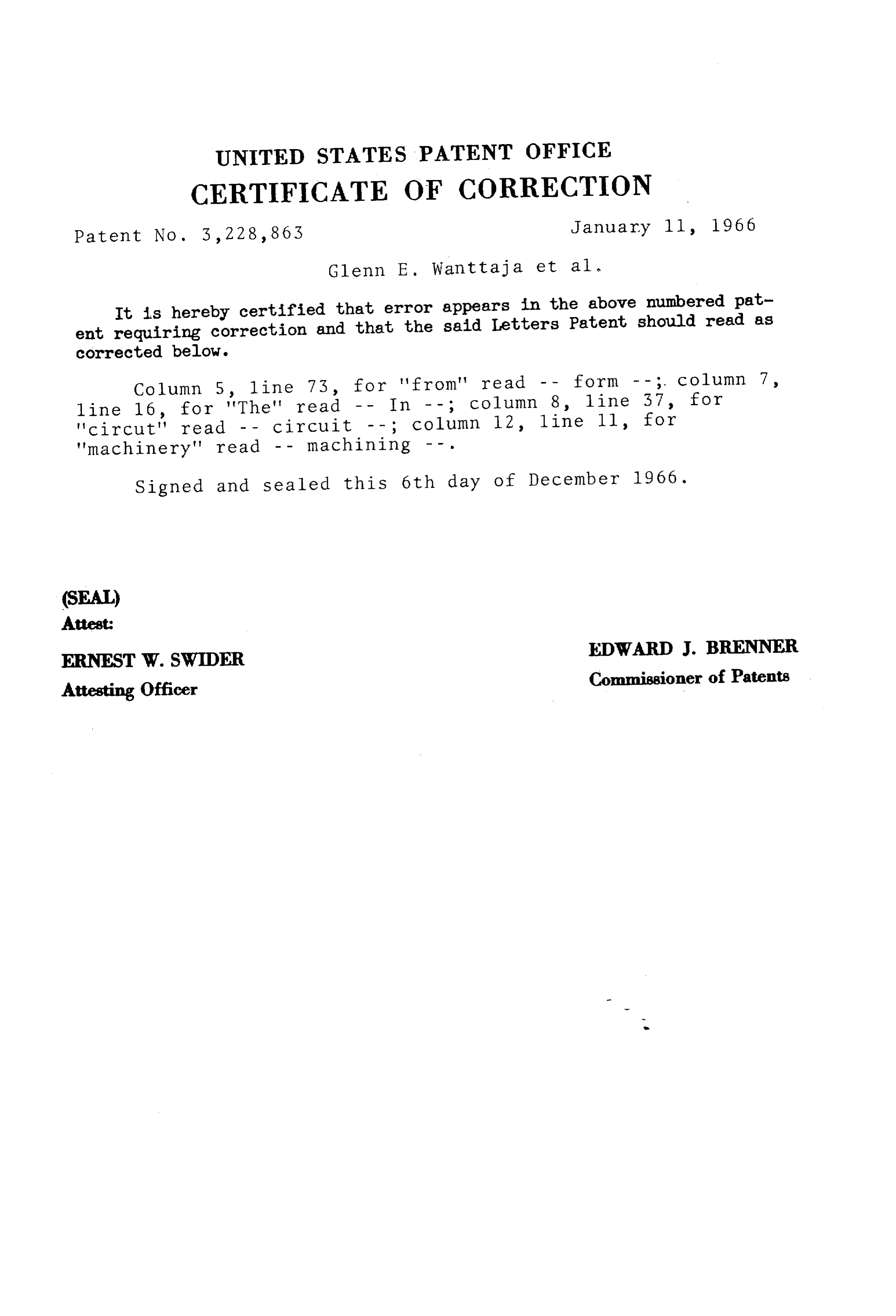
It is hereby certified that error appears in the above numbered pat ent requiring correction and that the said Letters Patent should read as corrected below.
Column 5, line 73, for 'from' read - - form - -; column 7, line 16, for "The" read -- In - -; column 8, line 37, for 'Circut" read - - circuit - -; column 12, line ll, for "machinery" read -- machining --.
Signed and sealed this 6th day of December 1966.
ERNEST W. SWIDER EDWARD J. BRENNER Attesting Officer Commissioner of Patents
Provenance
- Collection
- Cited prior art
- Original PDF
- patentimages.storage.googleapis.com →
- Filed
- 1960-10-27
- Pages
- 8
- Method
- pdftotext (the PDF's own text layer) + pdftoppm 300dpi page scans
- Source
- Google Patents bibliographic record
- Granted
- 1966-01-11
- Inventors
- Glenn E Wanttaja; Robert H Haupt; General Motors Corp
- Transcribed from
- patentimages.storage.googleapis.com →