patent · US5899199
Solar energy collector system
4 May 1999
Page 1 — bibliographic record
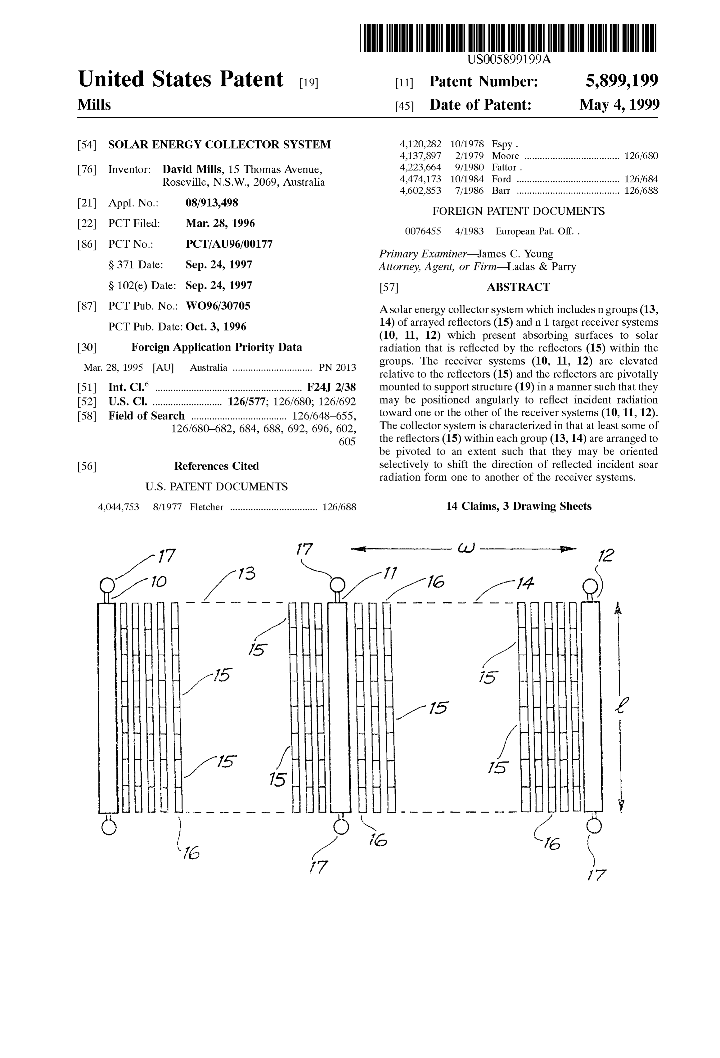
United States Patent (19) 11 Patent Number: 5,899,199 Mills (45) Date of Patent: May 4, 1999 54). SOLAR ENERGY COLLECTOR SYSTEM 4,120,282 10/1978 Espy.
4,137,897 2/1979 Moore ..................................... 126/680 76 Inventor: David Mills, 15 Thomas Avenue, 4,223,664 9/1980 Fattor. Roseville, N.S.W., 2069, Australia 4,474,173 10/1984 Ford ........................................ 126/684 s s s 4,602,853 7/1986 Barr ........................................ 126/688 21 Appl. No.: 08/913,498 FOREIGN PATENT DOCUMENTS 22 PCT Filed: Mar. 28, 1996 0076455 4/1983 European Pat. Off..
Primary Examiner James C. Yeung
S371 Date: Sep. 24, 1997 Attorney, Agent, or Firm-Ladas & Parry S 102(e) Date: Sep. 24, 1997 57 ABSTRACT 87 PCT Pub. No.: WO96/30705 A Solar energy collector System which includes n groups (13, PCT Pub. Date: Oct. 3, 1996 14) of arrayed reflectors (15) and in 1 target receiver systems (10, 11, 12) which present absorbing surfaces to solar 30 Foreign Application Priority Data radiation that is reflected by the reflectors (15) within the Mar. 28, 1995 AU Australia ............................... PN 2013 groups. The receiver systems (10, 11, 12) are elevated relative to the reflectors (15) and the reflectors are pivotally (51) Int. Cl." ......................................................... F24J 2/38 mounted to Support structure (19) in a manner Such that they 52 U.S. Cl. ........................... 126/577; 126/680; 126/692 may be positioned angularly to reflect incident radiation 58 Field of Search ..................................... 126/648-655, toward one or the other of the receiver systems (10, 11, 12). 126/680-682, 684, 688, 692, 696, 602, The collector System is characterized in that at least Some of 605 the reflectors (15) within each group (13,14) are arranged to be pivoted to an extent Such that they may be oriented 56) References Cited selectively to shift the direction of reflected incident soar
radiation form one to another of the receiver Systems.
4,044,753 8/1977 Fletcher .................................. 126/688 14 Claims, 3 Drawing Sheets
Page 2
Drawing sheet — no readable text.
Page 3
Drawing sheet — no readable text.
Page 4
Drawing sheet — no readable text.
Page 5
SOLAR ENERGY COLLECTOR SYSTEM level and are pivotably mounted to Support Structures whereby they may be positioned angularly to reflect incident
FIELD OF THE INVENTION radiation toward one or another of the receiver Systems. This invention relates to a Solar energy collector System Also, at least Some of the reflectors within the or each group are arranged to be pivoted to an extent Such that they may and, in particular, to a System which includes receivers be orientated selectively to shift the direction of reflected which function to absorb Solar radiation and reflectors which incident Solar radiation from one to another of the receiver are arranged to reflect incident Solar radiation toward the Systems.
receivers. The invention is hereinafter described largely in the context of a collector System which employs receivers be Inmade use of the above defined collector System, a choice may that incorporate evacuated tube-type collector elements receive theas reflected to which receiver System should be targeted to radiation from individual reflectors or which function to convert the energy content of incident Sub-groups of the reflectors which are arranged to shift the Solar radiation into thermal energy and to transfer the direction of reflected radiation from one to another of the thermal energy to heat eXchange fluid. However, it will be understood that the invention does have broader application, 15 receiver asSociated
Systems. Thus, when two receiver Systems are with the or each group of reflectors, daily and/or for example to Systems which include receivers in the form Seasonal changes in the angle of incident Solar radiation may of inverted cavity collectors and photovoltaic cells. be accommodated by varying the relative positions of adja BACKGROUND OF THE INVENTION cent reflectors in a manner to minimise Shading whilst, at the Same time, reflecting the incident radiation to one or the
A collector system of the type with which the present other or both of the two receiver systems associated with one invention is concerned is referred to as a Fresnel reflector group of reflectors.
System and, depending upon its configuration, may be However, the collector System need not necessarily be considered as an analogue of a parabolic dish or a linear designed to provide for 100% avoidance of shading. Some parabolic trough. When configured as an analogue of a Shading in the winter Season may be accepted in the interest parabolic trough, the collector System compriseS receivers 25 of minimising reflector spacing and increasing the level of which are Supported by Vertical masts and which are orien energy absorption in the Summer Season.
tated or arrayed to form a linearly extending target. The reflectors are positioned slightly above ground level and are thatTherefore, while it may be desirable in some installations all of the reflectors be arranged selectively to pivot to arrayed over an area that is Selected to provide reflection of Such an extent as to change the direction of reflection of the required amount of radiation toward the target receivers. incident radiation, it may be Sufficient in other installations The arrayed reflectors are orientated to reflect radiation that Some of the reflectors be arranged to pivot only to an toward one target, and the reflectors are pivotably mounted extent Sufficient to accommodate changes in the angle of and coupled to provide for Synchronised single-axis track incident radiation while maintaining orientation generally ing. toward one target. Also, in Some installations it may be The above described Fresnel reflector system permits the 35 appropriate that Some auxiliary reflectors have a fixed ori use of a large Scale target and provides for low construction entation.
costs relative to those that would be incurred in equivalent The collector System in accordance with the present Size parabolic trough or dish collector Systems. However, a invention may therefore be configured in a number of problem that is inherent in the use of ground arrayed 40 different ways:
reflectors is that shading occurs as a consequence of radia (a) With all reflectors (referred to as “direction changing tion blockage. This takes two forms, one in which radiation reflectors') being arranged to pivot to Such an extent as that would fall incident on reflectors is blocked by adjacent to shift the direction of reflection of radiation from one reflectors and the other in which radiation that is reflected toward the target by Some reflectorS is blocked by adjacent 45 receiver System to the other, and reflectors. This problem might be avoided by Spacing the (b) With some direction changing reflectors and with the reflectors in a manner to avoid shading, but this would have remaining reflectors (referred to as “angle changing the two-fold effect of reducing land utilisation efficiency and reflectors') arranged to change the angle of reflection expanding the distance between reflectors and associated slightly whilst maintaining orientation toward one of target receivers. This in turn would have the effect of 50 the receiver Systems.
reducing circumsolar acceptance for a given geometrical PREFERRED FEATURES OF THE INVENTION concentration ratio and, in the case of a multi-target receiver The relative proportions (i.e. numbers) of direction chang System, of increasing pipe run lengths between the receiver
Systems. ing reflectors and angle changing reflectors within a given The present invention seeks to avoid these problems, 55 installation will be determined by the size of the collector System, the elevation of the receiver Systems, the topography while preserving the benefit of the Fresnel reflector system, of the region at which the system is sited and the effective by providing for orientation of reflectors toward either one apertures that the receiver Systems present to the or each of two target receiver Systems. group of reflectors. However, it will be understood that SUMMARY OF THE INVENTION maximum flexibility will be obtained for a collector system 60 in which all of the reflectors are in the form of direction
The present invention may be defined broadly as provid changing reflectors.
ing a Solar energy collector System which comprises at least The direction changing reflectors and the angle changing one group of arrayed reflectors and at least two target reflectors may be considered as forming two Subgroups receiver Systems associated with the or each group of within a complete group of reflectors, and the reflectors reflectors. The receiver Systems are Supported above ground 65 within the respective Sub-groups may be linked mechani level and are elevated relative to the reflectors. The reflectors cally So as to move in Synchronism with changing angle of within the or each group are Supported at or above ground incident radiation. However, in the case of the direction
Page 6
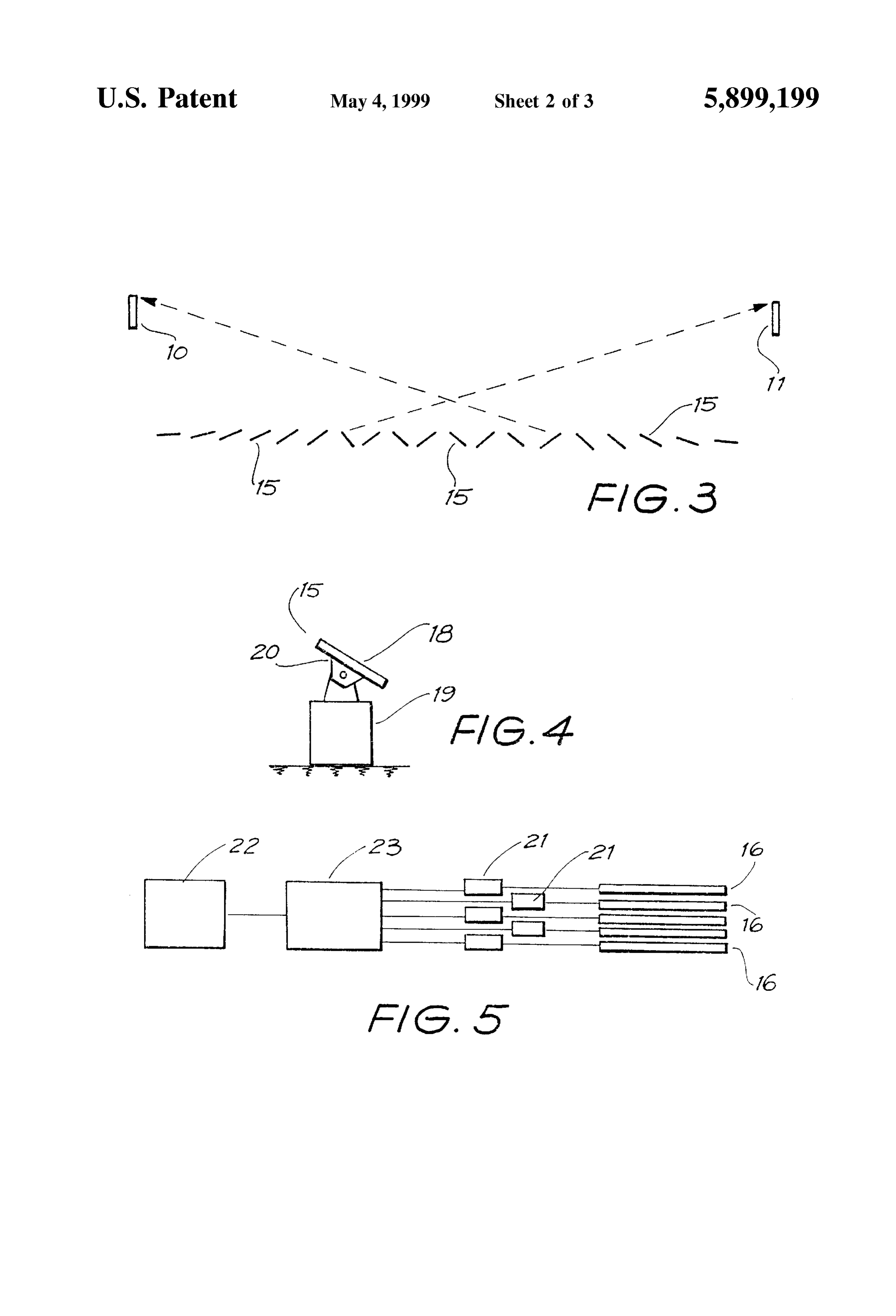
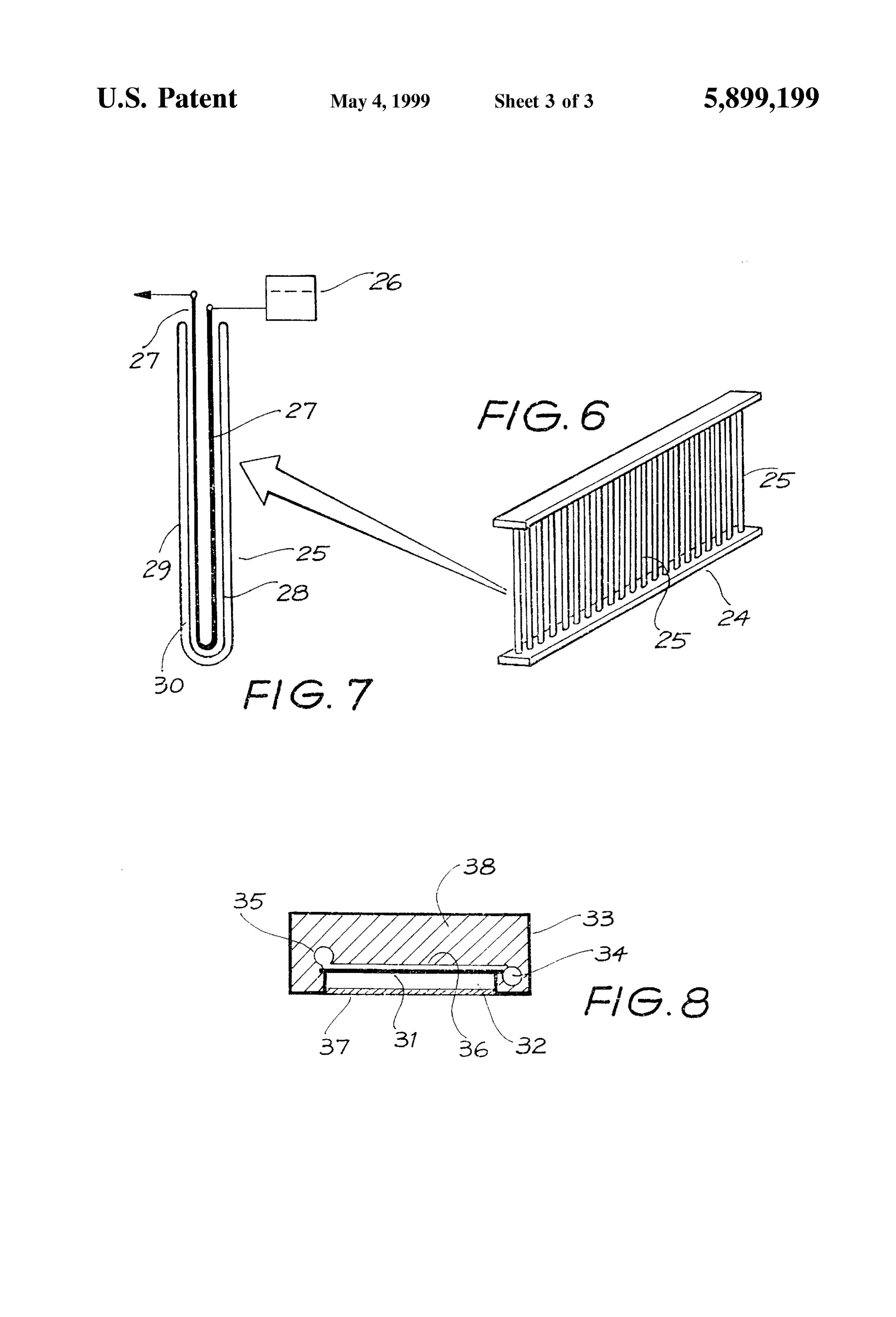
changing reflectors at least, it is preferred that the reflectors FIG.7 shows a single collector element removed from the within adjacent rows should be individually pivotable. receiver system illustrated in FIG. 6, and When more than two receiver systems are associated with FIG. 8 provides a diagrammatic representation in end the or each group of reflectors, the receiver Systems may be View of a receiver System which may be employed as an positioned to form the sides (or a portion of each of the alternative to the receiver system shown in FIG. 6. sides) of a geometric arrangement. For example, the receiver
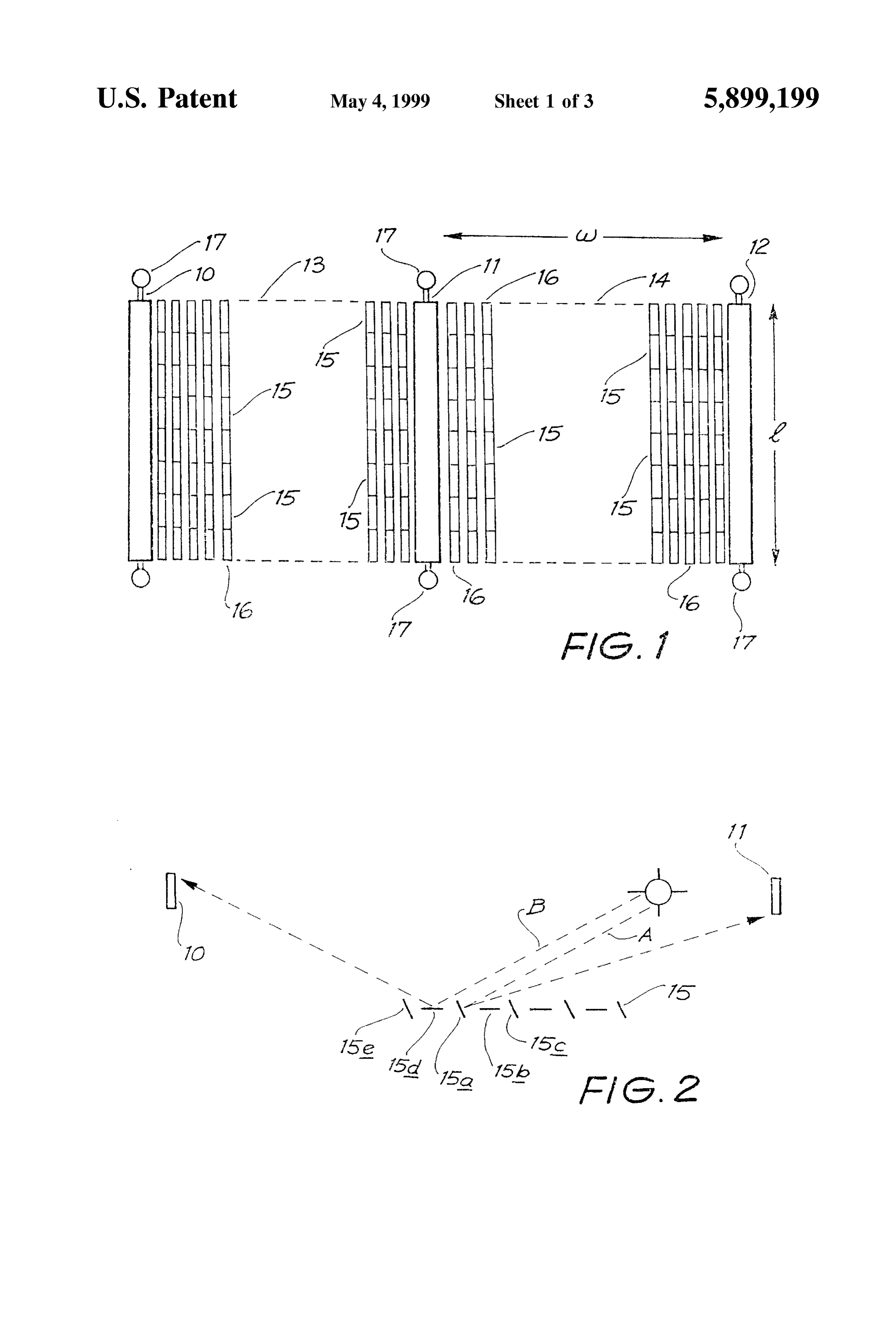
Systems as Seen from above may be arranged in the form of MODES FOR CARRYING OUT THE a hexagon and the reflectors may be grouped within and/or INVENTION without the boundary of the hexagon. As illustrated in FIG. 1, the solar collector system incor However, the receiver Systems preferably comprise porates three Spaced-apart, parallel receiver Systems 10, 11 arrayed receivers and the reflectors forming the or each and 12 which are separated by two reflector groupS 13 and group preferably are arrayed in rows extending parallel to 14. Each of the reflector groups comprises an array of the receiver Systems. reflectors 15 positioned in parallel rows 16 and disposed to The complete collector System may comprise a single 15 reflect incident radiation to one or the other of the adjacent group of reflectors positioned between two Spaced-apart receiver systems 10, 11 or 12. Each of the receiver systems Substantially parallel receiver Systems, but the collector has a length 1 typically in the order of 250 to 500 meters and System may comprise two groups of reflectors positioned each pair of receiver Systems will typically be Spaced apart between three Spaced-apart parallel receiver Systems, with by a reflector field width w in the order of 50 meters. With one of the receiver Systems presenting a target to radiation the System having these dimensions the receiver Systems reflected from the two groups of reflectors. This particular will be mounted to masts 17 having a height in the order of configuration may be repeated Such that for n reflector 13 meters and the reflectors will provide a ground cover in groups there will be n+1 receiver Systems. the order of 50%. The reflectors may be positioned with the AS indicated previously, each receiver System may be centre of their reflective surface 18 (FIG. 4) located approxi constituted by any device that has the capacity to absorb 25 mately 1 meter above the ground, So that the receiver Solar radiation and to convert Solar energy into a uSeable Systems are elevated with respect to all of the reflectors, form of energy. However, each receiver System preferably including any that may be located on high points of undu comprises a Solar-to-thermal energy exchange System and lating ground.
most preferably comprises a linear array of collector ele All of the reflectors 15 in each row 16 are coupled ments through which a heat eXchange fluid may be passed mechanically and are mounted to Support Structures 19 in a and which incorporate a Solar Selective Surface coating. In manner to permit them to be pivoted through an angle up to Such an embodiment of the invention the coating will approximately 90, in order that they might:
function to convert the energy content of incident Solar (a) Adjust for Small incremental changes in the angle of radiation to thermal energy and conduct the thermal energy incident radiation and ensure that reflected radiation is to the heat eXchange fluid. 35 Spread Substantially uniformly over the absorbing Sur AS previously Stated, the reflectors are located at or above face of the receiving systems 10, 11 and 12, and ground level and the receiver Systems are elevated relative (b) Adjust for changes in the angle of incident radiation to the reflectors. The reflectors may be Supported upon the that would give rise to shading. AS Stated previously, ground, or the entire collector System may be Supported shading may occur as a result of the reflectors blocking upon a platform above ground level. Such a platform may 40 either incident radiation or reflected radiation. comprise a building roof and the platform may be consid As illustrated in FIG. 2 of the drawings, alternative rows ered as being “ground” to the System. In a particular 16 of the reflectors 15 may be orientated to horizontal and application of the invention, the System may be mounted to acute angle positions, So that radiation along path A is a So-called Sawtooth shaped building roof, and the invention reflected by reflector 15a to the receiver system 11 without is particularly Suited to Such a Site because at least Some of 45 blockage being caused by either of the reflectors 15b or 15c, the reflectors will be positionable to accommodate the and radiation along path B is reflected by reflector 15d to different dispositions of the various reflectors relative to the receiver System 11 without blocking being caused by either receiver Systems. of the reflectors. 15a or 15e. However, it will be understood The invention will be more fully understood from the that the arrangement shown in FIG. 2 is purely illustrative of following description of a preferred embodiment of a com 50 one possible arrangement and that different reflector orien plete Solar collector System. The description is provided with tations may be appropriate to meet different conditions. One reference to the accompanying drawings. such condition is illustrated schematically in FIG. 3. Each reflector 15 may comprise a polished metal or a
BRIEF DESCRIPTION OF THE DRAWINGS glass mirror and its reflective surface 18 may be flat or be FIG. 1 shows a plan view of the complete collector system 55 formed with a slight concentrating curve. In an alternative incorporating three receiver Systems and two groups of arrangement, each reflector may be fabricated from a plas tics material and be coated or otherwise clad with a reflective reflectors, Surface.
FIG. 2 shows the basic concept of orientating reflectors to The reflector 15 is itself mounted to a support frame 20 avoid the shading of incident and reflected radiation, 60 which is carried by an axle that provides for Single-axis FIG. 3 shows a typical angular disposition of a group of pivoting of the reflector. The entire reflector assembly is reflectors located between two receiver Systems, carried by the ground engaging Support Structure 19, which FIG. 4 shows a typical mounting arrangement for one is dimensioned to Support the reflector about 1 meter above reflector element, the ground and which contains a drive mechanism for the FIG. 5 shows diagrammatically an electrical control SyS 65 reflector. Each reflector might typically have a length in the tem applicable to the reflectors, order of 2 meters, So that approximately 25 individual FIG. 6 shows a portion of one of the receiver systems, reflectors will form a single row 16 of reflectors.
Page 7
S 6
AS indicated in FIG. 5, a separate drive System is coupled reflectors, Support Structures pivotably mounting the to each row 16 of reflectors, and each drive System may reflectors, with Some of reflectors being orientated angularly comprise a plurality of Synchronised tracking motorS 21 or to reflect incident Solar radiation toward one of the receiver Stepping motorS for imparting uniform angular drive to the Systems and others of the reflectors being orientated angu reflectors 15 that form each of the rows 16. Drive to the larly to reflect incident Solar radiation to the other of the reflectors may be controlled by a sensor 22 which is receiver Systems, a drive means for imparting pivotal move arranged to detect the position of the Sun and generate ment to the reflectors, whereby the reflectors are positioned appropriate drive signals by way of a processor 23 for the angularly to maintain reflection of incident Solar radiation tracking motors 21 that are associated with the reflectors 15 toward the receiver Systems, and for Selectively pivoting at in the respective rows 16. In an alternative arrangement (not least Some of the reflectors to an extent Such that they are shown), the drive signal may be generated in a micropro reorientated to shift the direction of reflected Solar radiation ceSSor that is controlled by a computer generated Signal that from one of the receiver systems to the other receiver is representative of the position of the Sun at periodic System.
intervals. 2. The collector System as claimed in claim 1 wherein all Each of the receiver systems 10, 11 and 12 comprises a 15 of the reflectors within the group are arranged to be pivoted rack 24 of vertically extending tubular collector elements 25 by the drive means to Such an extent as to shift the direction which have a length in the order of 1.4 meters. The rack 24 of reflection of radiation from one to the other of the receiver mounts all of the collector elements 25 in close Spaced claims.
relationship and incorporates upper manifolds 26 which, as 3. The collector system as claimed in claim 1 wherein shown schematically in FIG. 7, are arranged to deliver water Some of the reflectors within the group are arranged to be to and carry Steam from each of the collector elements using pivoted by the drive means to Such an extent as to shift the a metal U-tube arrangement 27. direction of reflection of Solar radiation from one to the other The collector elements 25 comprise Single-ended glass of the receiver systems, and wherein other reflectors within tubes which have inner and outer tube components 28 and 29 the group are arranged to be pivoted by the drive means to Separated by an evacuated Space 30. The outer Surface of the 25 Such an extent as to change the angle of reflection of inner tube 28 is coated with a Solar Selective Surface coating, radiation but without shifting the direction of radiation from for example a graded or multi-layer cermet coating upon a one to the other of the receiver Systems. bright metal base, which is structured to absorb Solar radia 4. The collector system as claimed in claim 1 wherein tion and transmit thermal energy to the heat eXchange fluid each receiver System comprises a Solar-to-thermal energy which is passed through the tube. A metal fin (not shown) eXchange System.
may be located within the inner tube component 28 of the 5. The collector system as claimed in claim 4 wherein collector element to assist in energy transfer from the glass each receiver System comprises at least one rack of arrayed tube to the metal U-tube 27. collector elements through which a heat exchange fluid is Although the collector elements 25 are shown in FIG. 6 passed in use of the System.
as extending vertically between their upper and lower 35 6. The collector system as claimed in claim 5 wherein Supports, the collector elements may be inclined diagonally each collector element comprises a glass tube through which at an angle within the range 30 to 60 to the horizontal so heat eXchange fluid is passed, the tube having inner and as to reduce the effective height of the receiver System outer walls which define an evacuated Space and the inner Structure 24. Furthermore, in the interest of enhancing wall of the tube being coated with a Solar Selective Surface collector efficiency, auxiliary reflector elements (not shown) 40 coating.
may be provided to redirect to the collector elements 25 any 7. The collector system as claimed in claim 6 wherein the radiation that might otherwise pass between adjacent col collector tubes extend in a vertical direction between upper lector elements. and lower Support members of the rack. The alternative receiver system as shown in FIG. 8 of the 8. The collector system as claimed in claim 6 wherein the drawings is in the form of an inverted cavity receiver which, 45 collector tubes extend in a diagonal direction between upper as Seen in cross-section, comprises a thin metal foil-like and lower Support members of the rack.
plate 31 which is carried above a cavity 32 and within a sheet 9. The collector system as claimed in claim 4 wherein metal duct 33. Two longitudinally extending manifolds 34 each receiver System comprises at least one inverted cavity and 35 are supported within the duct 33, the lower one of type receiver having a horizontally disposed, longitudinally which is intended to carry water and the upper one of which 50 extending absorber plate, a glass panel disposed in parallel is intended to carry Steam. A plurality of parallel heat relationship to the plate, and a gas-containing cavity Sepa eXchange tubes 36 extend between and interconnect the rating the plate and the panel, the plate having an underSur manifolds 34 and 35, and the tubes 36 lay in contact with the face that is exposed to the cavity and which is coated with upper Surface of the plate 31. a Solar Selective Surface coating and the receiver incorpo The under surface of the plate 31 is clad with a solar 55 rating heat eXchange tubes in contact with an upper Surface Selective Surface coating of the type described above in the of the plate.
context of the collector elements 25, and a glass panel 37 10. The collector system as claimed in claim 1, wherein closes the cavity 32. The cavity is occupied by an inert gas there are n groups of the reflectors and n+1 Said receiver or stagnant air and the interior of the duct 33 is filled with Systems, each group of reflectors being positioned between an insulating material 38. 60 two of Said receiver Systems.
I claim: 11. The collector system as claimed in claim 10 wherein 1. A Solar energy collector System which comprises: a the reflectors within each group are arranged in linear rows group of reflectors arranged in parallel rows, the reflectors which extend parallel to the receiver Systems. being Supported at least at ground level, two Spaced-apart 12. The collector system as claimed in claim 11 wherein target receiver Systems located one at each end of the group 65 the reflectors within each row are coupled mechanically. of reflectors, the receiver Systems being Supported above 13. The collector system as claimed in claim 12 wherein ground level and being elevated relative to the group of the drive System is coupled to each row of reflectors and is
Page 8
arranged to effect relative pivoting of the reflectors in a 14. The collector system as claimed in claim 1 wherein manner to adjust for Small incremental changes in the angle each reflector is shaped to effect concentration of reflected of incident radiation, whereby radiation reflected from the Solar radiation.
reflectors is spread substantially uniformly over the absorb ing Surface of the receiving System to which the radiation is reflected.

Provenance
- Collection
- Cited prior art
- Original PDF
- patentimages.storage.googleapis.com →
- Filed
- 1996-03-28
- Pages
- 8
- Method
- pdftotext (the PDF's own text layer) + pdftoppm 300dpi page scans
- Source
- Google Patents bibliographic record
- Granted
- 1999-05-04
- Inventors
- David Mills
- Transcribed from
- patentimages.storage.googleapis.com →