patent · US5649416
Combined cycle power plant
22 July 1997
Page 1 — bibliographic record
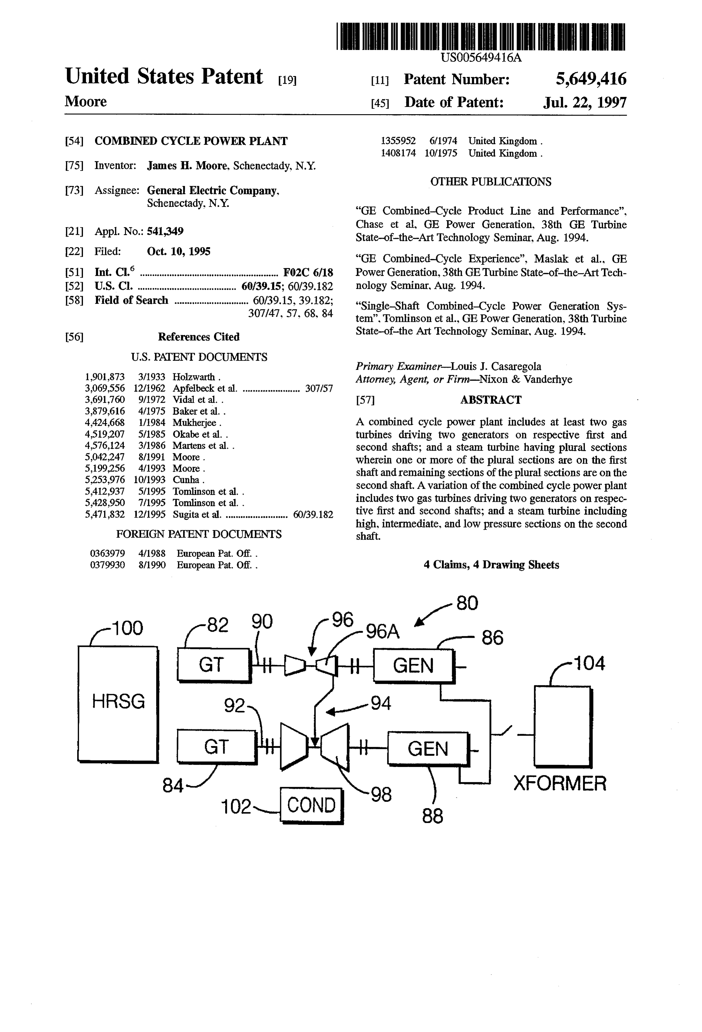
United States Patent 19 11 Patent Number: 5,649,416 Moore 45 Date of Patent: Jul. 22, 1997 54 COMBINED CYCLE POWER PLANT 1355952 6/1974 United Kingdom.
75 Inventor: James H. Moore, Schenectady, N.Y.
0. OTHER PUBLICATIONS 73) Assignee: General Electric Company,
Schenectady, N.Y. "GE Combined-Cycle Product Line and Performance", Chase et al., GE Power Generation, 38th GE Turbine 21) Appl. No.: 541,349 State-of-the-ArtTechnology Seminar, Aug. 1994. 22 Filed: Oct. 10, 1995 "GE Combined-Cycle Experience", Maslak et al., GE (51 int. C. m. FO2C 6/18 Power Generation, 38th GETurbine State-of-the-ArtTech 52 U.S. Cl. ................................... 60/39.15; 60/39.182 nology Seminar, Aug. 1994. 58 Field of Search ............................. 60/39.15, 39.182; "Single-Shaft Combined-Cycle Power Generation Sys 307/47, 57, 68,84 tem”. Tomlinson et al., GE Power Generation, 38th Turbine 56 References Cited State-of-the Art Technology Seminar. Aug. 1994.
Primary Examiner-Louis J. Casaregola 1901,873 3/1933 Holzwarth. Attorney, Agent, or Firm-Nixon & Vanderhye 3,069,556 12/1962 Apfelbeck et al. ....................... 307/57 3,691,760 9/1972 Vidal et al. . 57 ABSTRACT
4,424,668 1/1984 Mukherjee. A combined cycle power plant includes at least two gas 4,519,207 5/1985 Okabe et al. . turbines driving two generators on respective first and 4,576,124 3/1986 Martens et al.. second shafts; and a steam turbine having plural sections
wherein one or more of the plural sections are on the first
5,253,976 10/1993 Cunha. shaft and remaining sections of the plural sections are on the 5,412.937 5/1995 Tomlinson et al.. second shaft. A variation of the combined cycle power plant 5,423.950 7/1995 Tomlinson et a includes two gas turbines driving two generators on respec 5,471,832 12/1995 Sugita et al. 6039.182 tive first and second shafts; and a steam turbine including high, intermediate, and low pressure sections on the second
FOREIGN PATENT DOCUMENTS shaft.
O379930 8/1990 European Pat. Off. . 4 Claims, 4 Drawing Sheets
HRSG
XFORMER
Page 2
Drawing sheet — no readable text.
Page 3
Drawing sheet — no readable text.
Page 4
Drawing sheet — no readable text.
Page 5
Drawing sheet — no readable text.
Page 6
COMBINED CYCLE POWER PLANT turbine installed at a later date if the need for power increases. In order to operate the multi-shaft plant in a
TECHNICAL FIELD
simple cycle mode, means must be provided to dispose of the exhaust heat from the gas turbine. This can be done by
This invention relates to prime movers for the generation 5 dumping the steam produced in the HRSG directly to the of electricity in combined cycle power plants, utilizing two condenser, bypassing the steam turbine, or by bypassing the or more gas turbines. exhaust gas around the HRSG with an auxiliary exhaust stack. Either method adds cost and design and operating
BACKGROUND PRIOR ART complexity to the plant.
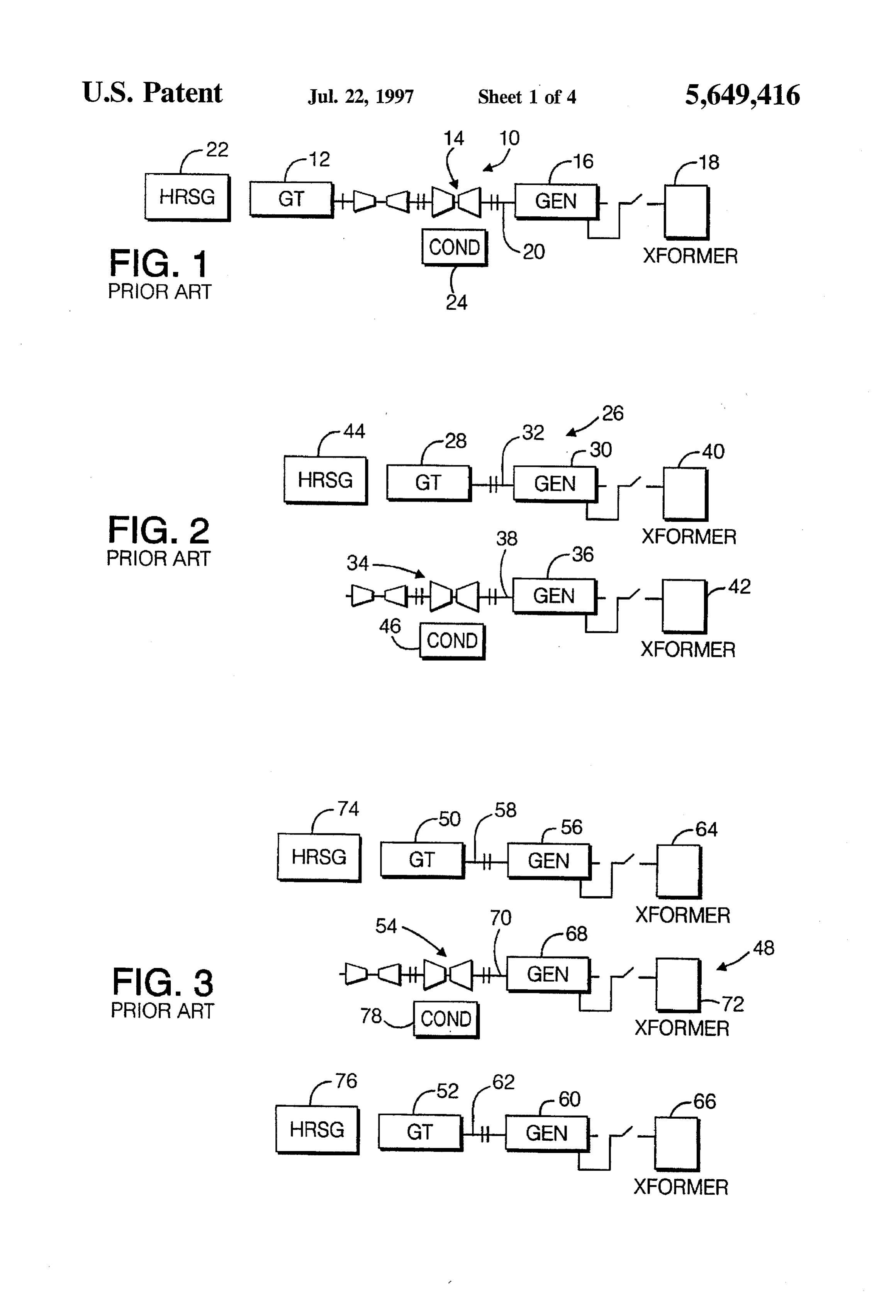
Combined-cycle power generation equipment is manu 10 In summary, the single-shaft plant of FIG. 1 has the factured by GE in two basic configurations, single-shaft and advantages of lower cost, higher efficiency, and simplicity of multi-shaft. Single-shaft combined cycle systems consist of design and operation; whereas the multi-shaft plant of FIG. one gas turbine, one steam turbine, one generator and one 2 has an advantage in operating flexibility in that it can be heat recovery steam generator (HRSG), with the gas turbine 15 operated in simple cycle as well as combined cycle mode. and steam turbine coupled to a single generator in a tandem More frequently, multi-shaft plants are designed with two arrangement. Multi-shaft combined-cycle systems have one gas turbines and a single steam turbine as shown in FIG. 3. or more gas turbine generators and HRSG's that supply The output of this plant is twice that of those in FIGS. 1 and steam through a common header to a separate single steam 2. The output of the single steam turbine is doubled and cost turbine generator unit. Both configurations perform their 20 and efficiency benefits due to scale are associated with the specific functions adequately, but the single-shaft configu steam turbine and condenser. However, to achieve the poten ration excels in the base load and midrange power genera tial benefits of operating flexibility expected of multi-shaft tion applications. plants, a separate HRSG for each gas turbine is required, so FIG. 1 is a simplified diagram of a conventional combined that the benefits of scale are not achieved by the entire steam cycle power plant including a single gas turbine, single 25 plant. Since the output of this plantis doubled, a comparison steam turbine and generator on a single-shaft, with a reheat, with a single-shaft plant must be made with one having two three-pressure-level steam cycle, represented by a heat identical units of the design shown in FIG. 1. In this recovery steam generator (HRSG). The maximum power comparison, the multi-shaft plant has advantages in terms of rating is limited, however, by the maximum capability of a cost and efficiency because of the single, larger steam single gas turbine. In combined cycle plants with unfired 30 turbine and condenser. However, these advantages are offset boilers, approximately two-thirds of the total power output somewhat by the following:
is produced by the gas turbine and one-third by the steam 1. There are three separate machines rather than two, with turbine. Supplemental firing of the heat recovery steam a greater total number of thrust and journal bearings generator can increase the total power output and the portion with associated power losses. of the total power produced by the steam turbine, but only 35 2. There are cost and efficiency penalties associated with with a reduction in overall plant thermal efficiency. The three one-third size rather than two half-size genera largest gas turbines produced today are rated at somewhat toIS.
less than 350 MW. Therefore, the steam turbine of a single 3. The practical construction of a plant with three separate shaft combined cycle plant has a maximum rating less than machines to achieve a degree of independent operation 175 MW. This is much smaller than the steam turbines of 40 modem fossil-fueled steam plants of high efficiency, which involves considerable complexity in piping, valves and are more typically 500 to 900 MW. The single-shaft control equipment. The addition of isolation valves in combined-cycle system has emerged as the preferred con all main steam, and cold and hot reheat steam lines, and figuration for single phase applications in which the gas in numerous auxiliary steam lines adds cost and para sitic pressure drop and also reduces reliability.
turbine and steam turbine installation and commercial opera 45 The net effect is that the multi-shaft tion are concurrent. plant with two gas turbines has a net efficiency advantage over the two half-size
A conventional multi-shaft combined-cycle system single shaft units. Neither configuration is considered to configuration, employing a single gas turbine, single steam have a clear cost advantage over the other. turbine and a single HRSG, is illustrated in FIG. 2. This With this background, a brief summary of the problems configuration may be applied in phased installations in 50 addressed by this invention is provided below. The steam which the gas turbines are installed and operated prior to the cycle portion of a combined cycle power plant is more steam cycle installation, and it is frequently applied where it expensive to build and has a lower thermal efficiency than is is desired to operate the gas turbines independently of the the case for a modem conventional steam power plant. This steam system. is due, in part, to basic differences in the thermodynamic The steam turbine in a multi-shaft configuration with a 55 cycles of heat recovery and conventional, fired-boiler single gas turbine has the same rating as that of the single applications, which can not be changed. However, it is also shaft plant, but there is no cost or efficiency benefit due to due to the Small size and power rating of the equipment. Scale. In fact, the multi-shaft arrangement has somewhat Conventional steam power plants benefit in both lower higher cost and poorer efficiency, primarily due to the fact cost and higher efficiency through the economies of scale of that there are two generators, both smaller than the single large ratings. A traditional rule of thumb regarding cost is generator of the single-shaft machine, and there are a larger that the doubling of plant rating results in a ten percent number of bearings with their associated power losses. reduction in cost. The cost of one large generating unit The usual reason for selecting the multi-shaft arrangement according to this rule would be expected to cost on the order is that it permits the operation of the gas turbine in a simple of ten percent less than that for a plant with two half-size cycle mode, without operating the steam turbine. This might 65 units.
be desirable for peaking operation or for a phased installa Efficiency is also improved with increased size and power tion in which the gas turbine is installed first and the steam rating. As with all turbomachinery, the internal efficiency of
Page 7
the steam turbine is a strong function of inlet volumetric has been developed to begin admission of steam into the flow, which is directly proportional to rating. Also, as is well steam turbine. Prior to this point, cooling steam from an known, the thermal efficiency of the Rankine cycle increases auxiliary source is required for cooling purposes in the LP with the pressure at which steam is generated. Increasing turbine to remove heat generated by rotational losses. pressure, however, reduces the volumetric flow of the steam 5 A variation on this basic arrangement including separate at the turbine inlet, reducing the internal expansion effi HRSG's, transformers and circuit breakers, permits the ciency. This offsetting effect in overall efficiency, however, primary shaft with the HP/IP steam turbine section to be is much greater at low volumetric flow than at higher started and synchronized to the grid first. When sufficient volumetric flow. Therefore, an additional performance steam production rate is established in the associated HRSG, related benefit of increasing turbine size is that higher steam O steam is admitted to the steam turbine to produce electrical throttle pressure can be utilized more effectively. power from the primary shaft, and torque on the LP shaft for accelerating to full speed.
SUMMARY OF THE INVENTION
Another alternative arrangement includes separate HP and
The object of the invention is to provide for a combined IP sections on separate shafts and two double-flow LP cycle power plant having the advantages and desirable 15 sections, one on each shaft.
characteristics of the present single-shaft plant designs, but In the basic configuration, the equipment arrangement on utilizing more than one gas turbine and achieving the each shaft is with the generator on one end and the steam and potential cost and performance benefits of larger steam cycle gas turbine connected by solid couplings and utilizing a equipment. 20 Single thrust bearing to maintain proper axial alignment To this end, two or more rotating power trains are between rotating and stationary components in the manner employed, depending upon the required total power output described in U.S. Pat. No. 4,961.310. It is recognized that of the plant. Each shaft is made up of one gasturbine and one other arrangements, such as one having the generator generator, and preferably includes one or more sections of a between the gas and steam turbines are possible and are steam turbine. In the basic configuration, the machine con 25 within the scope of this invention. Furthermore, the inven sists of two shafts, driving separate electric generators but tion is equally applicable with other steam cycles, such as operated together as a single unit. The primary shaft consists non-reheat or double-reheat, or one with more or less than of a gas turbine in combination with one or more sections of three separate pressure levels, and with bottoming cycles a steam turbine driving one generator; the secondary shaft having other working fluids or fluid mixtures. consists of a second gas turbine combined with the remain 30 In still another alternative configuration, the steam turbine ing sections of the steam turbine driving the second genera is on only one of the two shafts. This design also achieves tor. The various steam turbine sections on the two shafts the cost and performance benefits of the single large steam together make up a single cross-compound steam turbine. turbine without requiring the third shaft and generator of the Variations in the basic configuration are possible, as is the multi-shaft design.
extension to larger ratings based on three or more gas 35 The description of the invention, to this point, has for turbines. The machine has the basic features and character convenience, been based on an application employing two istics of current single-shaft combined cycle units, but gas turbines. The concept, however, applies equally well to unlike current designs, is not limited in output by the plants with more than two gas turbines. For example, three maximum power rating of a single gas turbine. The reduced gas turbines can be employed in which the first shaft has no cost and improved thermal efficiency of larger steam cycle 40 steam turbine elements, and can be operated in simple cycle, components is achieved without the use of a separate steam and to produce steam for starting the other two shafts by turbine generator. Therefore, there is always one less rotat driving the steam turbine. An extension to four gas turbines ing power train, including generator, than required by cur is also described herein.
rent multi-shaft combined cycle plants. A combined cycle In its broader aspects then, the present invention relates to power plant constructed in accordance with this invention 45 a combined cycle power plant comprising at least two gas will have lower cost and better thermal efficiency than that turbines driving two generators on respective first and of plants built today with either single-shaft or multi-shaft second shafts; and at least one steam turbine having plural designs. sections wherein one or more of the plural sections are on More specifically, the basic and presently preferred con the first shaft and remaining sections of the plural sections figuration of the present invention employs two gas turbines, 50 are on the second shaft.
and one steam turbine on two shafts, and as in a conventional In another aspect, the invention relates to a combined steam plant with a cross compound steam turbine, both cycle power plant comprising two gas turbines driving two shafts always operate together. This permits cost savings generators on respective first and second shafts; and a steam through use of only one boiler, one condenser, one trans former and one circuit breaker for connection to the grid. 55 turbine including high, intermediate, and low pressure sec The combined high-pressure (HP)/intermediate-pressure tions on the second shaft.
(IP) section of the steam turbine is coupled with one gas become Other objects and advantages of the invention will turbine on a primary shaft and the low-pressure (LP) section lows. apparent from the detailed description which fol is coupled with the second gas turbine on a secondary shaft.
The LP steam turbine section on the secondary shaft 60 BRIEF DESCRIPTION OF THE DRAWINGS receives, as its input, steam from the exhaust of the DP section on the primary shaft. The two generators are tied FIG. 1 is a simplified diagram of a conventional single together electrically prior to startup, or at low speed, by shaft combined cycle power plant;
applying excitation to both fields. They are then accelerated FIG. 2 is a simplified diagram of a conventional multi to rated speed together and synchronized to the electrical 65 shaft combined cycle power plant;
grid as a single generator. The gas turbines are held at low FIG. 3 is a simplified diagram of a conventional, three load until the HRSG is warmed and sufficient steam pressure shaft, two gas turbine combined cycle power plant;
Page 8
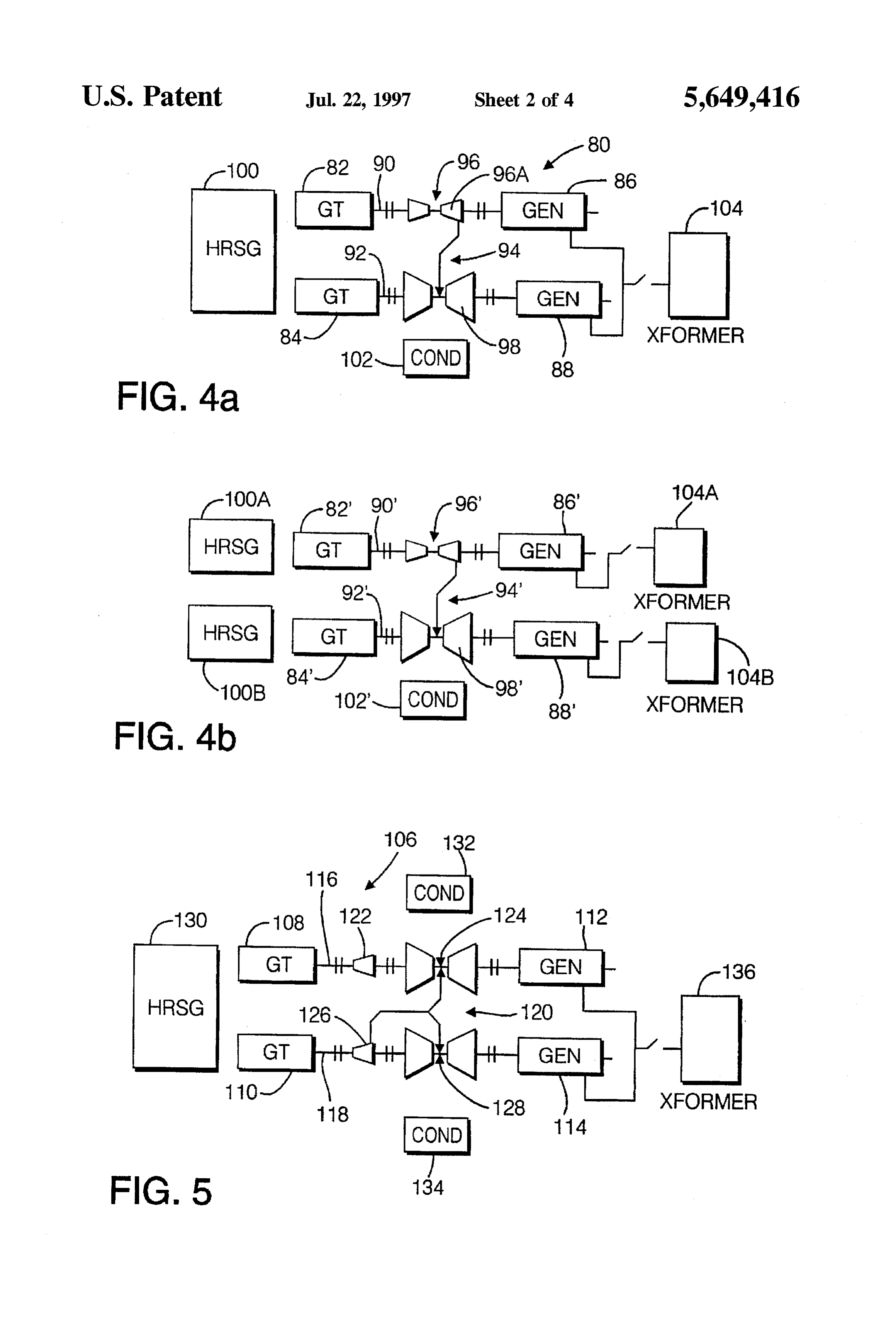
FIG. 4a is a simplified diagram of a combined cycle receiving exhaust gases from both gas turbines 82 and 84, power plant in accordance with this invention, employing along with condensed steam from the steam turbine con two gas turbines and one steam turbine on two shafts; denser 102. In addition, only one transformer 104 (and thus, FIG. 4b is a variation of FIG. 4a, wherein separate only one circuit breaker) is required for connection to the HRSG's, transformers and circuit breakers are employed power grid.
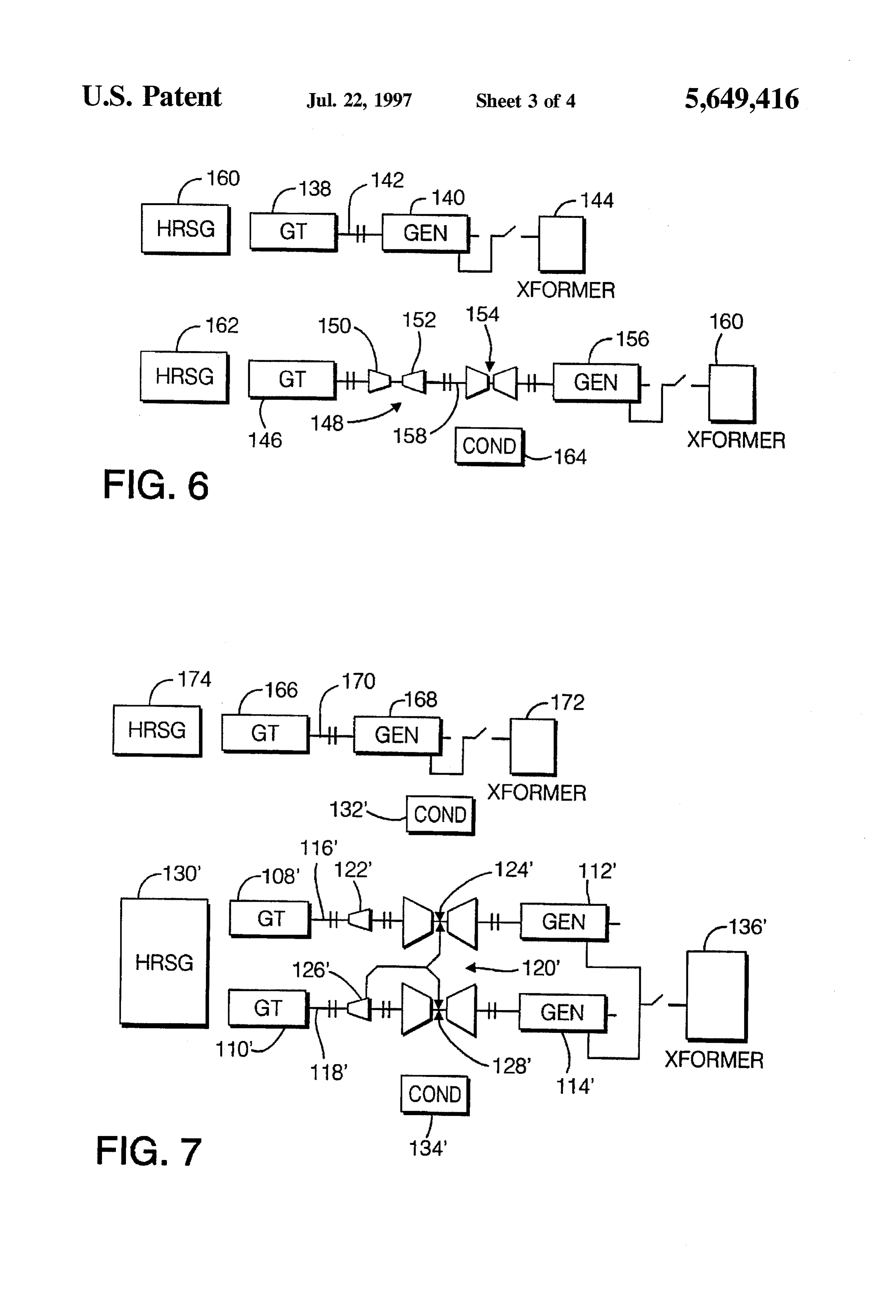
with the pair of gas turbines; In the above described arrangement, the two generators FIG. 5 is a simplified diagram of another variation of FIG. 86, 88 are tied together electrically prior to startup, or at low 4a, employing separate high and intermediate pressure sec speed, by applying excitation to both fields. The generators tions of the steam turbine on separate shafts and two double 10 86, 88 are then accelerated to rated speed and synchronized flow low pressure sections, one on each shaft; to the power grid as a single generator. The gas turbines 82, FIG. 6 is a variation of FIG. 4b wherein the steam turbine 84 are then held at low load until sufficient steam pressure sections are all on one of the two shafts; is developed in HRSG 100 to permit admission of steam to the steam turbine 94. Prior to this point, cooling steam from
FIG. 7 is a simplified diagram of a combined cycle power an auxiliary plant in accordance with the invention, utilizing three gas 15 purposes in the source (not shown) is required for cooling turbines, in which one shaft has no steam turbine elements; LP turbine section 98 to remove heat and; generated by rotational losses. Turning now to FIG. 4b, a variation of the preferred
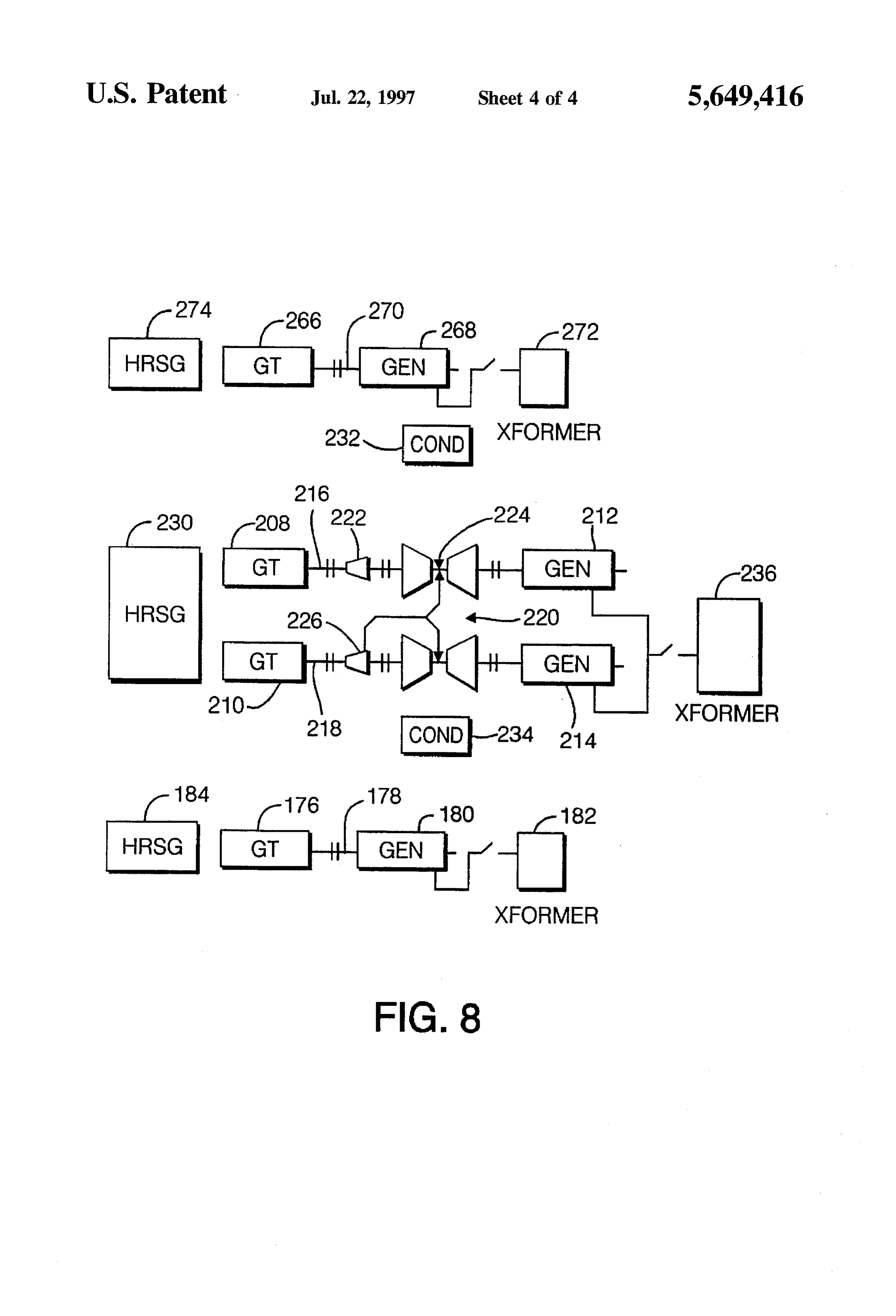
FIG. 8 is a still another embodiment of the invention, arrangement utilizing four gas turbines. of FIG. 4a is illustrated. The arrangement here
is similar to that shown in FIG. 4a, except that each gas
BEST MODE FOR CARRYING OUT THE turbine 82, 84 has its own HRSG 100A and 100B, INVENTION respectively, and each generator 86", 88 has its own trans former 104A and 104B, respectively (and thus separate
With reference again to FIG. 1, a conventional single circuit breakers). This arrangement permits the primary shaft combined cycle power plant 10 is shown to include a 25 shaft 90' with the HP/IP steam turbine Section 96 to be single gas turbine 12, a single steam turbine 14 and a started and synchronized to the grid first. Then, after suffi generator 16 connected to a transformer 18. The unit is cient steam production is established in HRSG100A, steam arranged on a single rotor or shaft 20. The plant also includes is admitted to the steam turbine 94 to produce electrical a conventional heat recovery steam generator, or HRSG, 22 power from the primary shaft 90' and torque on the second in which energy from the exhaust gases exiting the gas 30 ary shaft 92 for accelerating to full speed. turbine 12 is recovered. More specifically, water from the The advantages here are that the capacity of the auxiliary steam turbine condenser 24 is converted to steam which, in steam source is greatly reduced because the need for cooling turn, drives the steam turbine 14. steamin the LP turbine section 98, and the need for a means FIG. 2 illustrates a conventional multi-shaft combined of cranking the secondary shaft 92 are eliminated. These cycle power plant 26 which includes a single gas turbine 28 35 benefits must be weighed against the greater cost of the two coupled to a generator 30 on one shaft32, and a single steam separate HRSG's 100A and 100B, associated piping and turbine 34 coupled to its own generator 36 via a second shaft isolating valves, as well as separate transformers 104A, 38. In this arrangement, generator 30 is connected to one 104B and associated circuit breakers. The machines of both transformer 40, while generator 36 is connected to a second FIGS. 4a and 4b, in comparison with the multi-shaft transformer 42. An HRSG 44 interacts with the gas turbine 40 arrangement of FIG. 3, have the characteristics, advantages 28 and steam turbine 34 (via condenser 46) essentially in the and disadvantages of single-shaft combined cycle plants. same manner as in the single shaft configuration. The term single-shaft may be applied here because there is FIG. 3 illustrates another conventional multi-shaft one shaft for each gas turbine, producing power from both arrangement 48 which includes two gas turbines 50, 52 and the gas turbine and from its exhaust heat by means of heat a single steam turbine 54. Here, gas turbine 50 is coupled to 45 recovery in a steam cycle. No separate, additional generator generator 56 on one shaft 58, while gas turbine 52 is coupled and power train is required to produce power in the steam to a second generator 60 on a second shaft 62. Generator 56 cycle.
is connected to a first transformer 64, while generator 60 is It should be recognized that the LP section 98, 98' shown connected to a second transformer 66. The single steam as double-flowed in FIGS. 4a and 4b, respectively, could be turbine S4 is coupled to a third generator 68 on a third shaft 50 single-flowed, or could have three or four flows in two 70. Generator 68 is connected to a third transformer 72. In casings as required to achieve the optimum exhaust annulus this arrangement, a pair of HRSG's 74, 76 are required, one area for the application. Also, the HP and IPsections 96,96 for each gas turbine, with condensed steam from steam could be in separate casings rather than combined in one. turbine condenser 78 supplying both HRSG's. With reference now to FIG. 5, another combined cycle Turning now to FIG. 4a, the basic, and presently 55 arrangement in accordance with this invention is shown preferred, combined cycle power plant configuration in which is similar to that shown in FIG. 4a with the exception accordance with this invention is illustrated, also in simpli that the steam turbine has HP and IP sections on separate fied form. In this arrangement, a combined cycle power shafts, and an LP section on each shaft. Specifically, the plant 80 includes a pair of gas turbines 82, 84 coupled to combined cycle plant 106 includes a pair of gas turbines respective generators 86.88 via shafts 90, 92. A single 60 108, 110 coupled to respective generators 112, 114 via cross-compound steam turbine 94 is arranged with the separate shafts 116, 118. The steam turbine 120 is arranged combined HP/IP section 96 on the primary shaft 90, and the with an HP section 122 and a double flow LP section 124 on LP section 98 on the secondary shaft 92. The LP section 98 the one shaft 116, and an IPsection 126 and double flow LP receives, as its input, steam from the exhaust of the IP section 128 on the other shaft 118. In this arrangement, a section 96A on the primary shaft 90. As in any conventional 65 single HRSG 130 and two condensers 132, 134 are cross-compound steam turbine, both shafts 90 and 92 work employed. Generators 112, 114 are connected to a single together. As a result, only one HRSG 100 is required, transformer 136 via a circuit breaker. This design is more
Page 9
costly because there are more steam turbine casings and two FIG. 8 illustrates still another combined cycle plant which condensers, and would be employed where the application builds on the plant shown in FIG. 7 including a fourth gas requires more exhaust annulus area than could be achieved turbine 176 on a separate shaft 178 coupled directly to a with one double-flow LP section. fourth generator 180 connected to a third transformer 182. A In still another variation shown in FIG. 6, the steam 5 third HRSG 184 is employed for use with the gas turbine turbine is on only one of two shafts. Specifically, a first gas 176, the former receiving condensed steam from the steam turbine 138 is coupled to a generator 140 on one shaft 142, condenser 234. The remaining plant components are as and the generator 140 is connected to a first transformer 144. shown and described in connection with FIGS. 7 and 5. A second gas turbine 146, steam turbine 148 (including HP, These remaining components have reference numbers simi IP and LP sections 150, 152 and 154, respectively) and a 10 lar to those used in FIG.7 but with the prefix "2" substituted generator 156 are arranged on a second shaft 158. The for the prefix “1” or “1”.
generator 156 is connected to a second and separate trans While the invention has been described in connection former 160. Each gas turbine 138, 146 is associated with an with what is presently considered to be the most practical HRSG 160, 162, respectively, which receive condensed and preferred embodiment, it is to be understood that the steam from the condenser 164 of the steam turbine 48. 15 invention is not to be limited to the disclosed embodiment, A benefit of this alternative arrangement is that either but on the contrary, is intended to cover various modifica shaft 142, 158 can be operated alone, one in simple cycle tions and equivalent arrangements included within the spirit and the other in combined cycle. For combined cycle and scope of the appended claims. operation with both shafts, the one without the steam turbine 20 What is claimed is:
(shaft 142) starts first, and produces electrical power while 1. A combined cycle power plant comprising at least two developing steam pressure in its associated HRSG 160. This gas turbines driving two generators on respective first and steam is then used to start the second shaft 158 by driving second shafts; and a single steam turbine having plural with the steam turbine 148, completely eliminating the need sections including a single high pressure section, wherein for an auxiliary steam source. The cost of equipment for 25 one or more of said plural sections are on said first shaft and cranking the gas turbine 138 for starting is reduced for the remaining sections of said plural sections are on said second shaft.
first shaft 142 because there is no steam-turbine-rotor iner tial load, and can be eliminated completely for the second 2. A combined cycle power plant comprising at least two shaft 158. Also, it is not necessary that the two HRSG's 160, gas turbines driving two generators on respective first and 162 be identical. For instance, there may be an advantage in second shafts; and a steam turbine having plural sections reduced cost and complexity to have a reheater section only 30 wherein one or more of said plural sections are on said first in the HRSG 162 corresponding to the shaft 158 with the shaft and remaining sections of said plural sections are on steam turbine 148. said second shaft, and further comprising a single heat FIG. 7 illustrates a combined cycle plant employing three recovery steam generator by which exhaust gas from the at least two gas turbines is used to heat condensed stream from gas turbines. A first gas turbine 166 is coupled directly to a 35 the steam turbine.
generator 168 on a first shaft 170. The generator, in turn, is 3. A combined cycle power plant comprising at least two connected to a first transformer 172. Gas turbine 166 has its own HRSG 174. The remaining components of this plant are second shafts;driving gas turbines two generators on respective first and and a steam turbine having plural sections essentially as described in connection with FIG. 5 and, for wherein one or more of said plural sections are on said first convenience, the same reference numerals are used in the 40 drawings, but with a "prime" designation added to denote shaft and remaining sections of said plural sections are on corresponding components. The steam turbine 120', said second shaft, wherein high and intermediate steam however, has 50 percent greater power output in this plant turbine section are on said one shaft and a low pressure than in the two gas turbine plant of FIG. 5 and, therefore, has steam turbine section is on said second shaft, and further cost and efficiency advantages due to the economies of scale. 45 whereinsteamsection.
from said intermediate section is input to said
With the third gas turbine 166 on a separate shaft 170, this low4.pressure
The combined cycle power plant of claim 1 and arrangement can be operated in simple cycle, and to produce including a single transformer connected to both generators. steam for starting the other two shafts 116, 118' by driving the steam turbine 120'.
Provenance
- Collection
- Cited prior art
- Original PDF
- patentimages.storage.googleapis.com →
- Filed
- 1995-10-10
- Pages
- 9
- Method
- pdftotext (the PDF's own text layer) + pdftoppm 300dpi page scans
- Source
- Google Patents bibliographic record
- Granted
- 1997-07-22
- Inventors
- James H. Moore; General Electric Co
- Transcribed from
- patentimages.storage.googleapis.com →