patent · US6290185
Solar thermal rocket
18 September 2001
Page 1 — bibliographic record
(12) United States Patent (10) Patent No.: US 6,290,185 B1 DeMars et al. (45) Date of Patent: Sep. 18, 2001
(54) SOLAR THERMAL ROCKET FOREIGN PATENT DOCUMENTS
(75) Inventors: Richard Vail DeMars; Barry John 2125157 2/1984 (GB) .................................... 244/172 Miles, both of Lynchburg; Barry Gene
Miller, Goode; Kurt Ogg Westerman, * cited by examiner
Forest, all of VA (US)
Primary Examiner-Charles T. Jordan (73) Assignee: BWX Technologies, Inc., Lynchburg, ASSistant Examiner Tien Dinh VA (US) (74) Attorney, Agent, or Firm-Robert J. Edwards; D. Neil LaHaye (*) Notice: Subject to any disclaimer, the term of this patent is extended or adjusted under 35 (57) ABSTRACT
U.S.C. 154(b) by 0 days. A Solar thermal rocket that includes a thermal energy Storage Section, a radiant inter-heater, a primary Solar concentrator, (21) Appl. No.: 09/427,844 and a propulsion nozzle. The primary Solar concentrator is (22) Filed: Oct. 26, 1999 Selectively movable to direct Solar energy to either the thermal energy Storage Section or to the radiant inter-heater.
(51) Int. Cl." ....................................................... B64G 1/40 The thermal energy Storage Section, along with insulation, is (52) U.S. Cl. ........................ 244/172; 60/203.1; 60/641.8; arranged to define a cavity Such that a focused beam of Solar 244/173 rays can enter the cavity through an aperture in the insula (58) Field of Search .................................. 244/63, 158 R, tion. The thermal energy Storage Section typically absorbs 244/172, 173, 62; 60/203.1, 229, 228, 6418, and Stores Solar energy during the non-propulsion portion of 641.11, 641.12, 641.13, 641.14, 641.15, the orbital period. The Solar rays are captured and absorbed 2001 and thereby heat the thermal energy Storage Section to very high temperatures. A radiant inter-heater directly receives (56) References Cited concentrated Solar rays and transferS the heat to the propel
lant during the propulsion phase. The propellant heated by the inter-heater is directed through the thermal energy Stor 3,097,480 * 7/1963 Sohn. age Section where it is further heated to its peak temperature 3,825,211 * 7/1974 Minovitch. and then expelled through the nozzle to produce thrust. With 4,354,348 * 10/1982 Lee. the inter-heater, the rate of heat extraction from the thermal 4,452,047 * 6/1984 Hunt et al.. energy Storage Section is reduced, prolonging the period of 4,528,978 * 7/1985 Robinson. peak propellant temperature, resulting in an overall higher 4,781,018 * 11/1988 Shoji. average Specific impulse.
6,065,284 * 5/2000 Horner et al.. 2 Claims, 2 Drawing Sheets
RCN
Page 2
Drawing sheet — no readable text.
Page 3
Drawing sheet — no readable text.
Page 4
SOLAR THERMAL ROCKET energy Storage Section to allow heating of the propellant above the temperature limit of the thermal energy Storage
BACKGROUND OF THE INVENTION materials. The higher temperatures improve orbit transfer 1. Field of the Invention performance.
The invention is generally related to rockets and more A problem with both the direct gain and the hybrid particularly to Solar thermal rockets. designs is that retention of thermal energy becomes much 2. General Background more difficult as the peak cavity temperature increases. Multi-foil insulation is often used to confine heat to the hot
Solar thermal rockets were first proposed in 1954 as a way Zone. At very high temperatures, heat loSS out of the cavity to provide greater Specific impulse than chemical rockets. aperture and through the multi-foil insulation is dominated Solar thermal rockets use the Sun's energy to heat a propel lant (typically hydrogen) to extremely high temperatures and the radiation
fourth heat transfer, which varies with temperature to power. Raising the cavity temperature by ten then expel the hot gas through a nozzle to provide thrust. The percent results in more high temperature and low molecular weight of the propellant loSS. Heat input must bethan a forty-percent increase in heat significantly increased to compen combine to produce a specific impulse of two to four times 15 Sate for the larger heat losses if very high that of a chemical rocket. Generally, Solar thermal rockets to be obtained. AS previously indicated, the temperatures Size of the are
Space have been of either a “direct gain” design in which the deployable Solar concentrators is already a limiting factor in propellant is heated directly by very large Solar collectors Solar thermal rocket Systems.
during a long continuous burn, or of a “thermal energy
Storage' design which collects and Stores energy from Some Solar powered rocket Systems incorporate a Sec smaller collectors for use in short impulsive “burns'. ondary concentrator between the primary concentrator and Recently, a “Hybrid Direct Gain/Thermal Energy Storage” the cavity to reduce the size of the aperture, which in turn design has been proposed that combines the high reduces the amount of heat that can escape by radiation out temperature propellant capability of the direct gain design of the cavity. LOSSes due to less-than-perfect reflection in the with the smaller collector feature of the thermal energy 25 Secondary concentrator can be significant. Although it is Storage design. Each of these designs has advantages and theoretically possible to limit these losses to less than ten disadvantages. percent, realistic losses are on the order of fifteen to thirty The direct gain rocket requires very large Solar collectors five percent of the power from the primary concentrator. (concentrators) to provide Sufficient energy to heat the In addition to high heat losses, very high temperature hydrogen propellant as it passes through a cavity comprised designs present material, Structural, and manufacturing chal of refractory metal tubes or encapsulated foam (typically lenges that are difficult to Solve individually and even more rhenium). The advantage of this type of rocket is that the difficult to Solve in a System, particularly under normal temperature of the propellant can be extremely high budget constraints. At the desired very high temperatures, (theoretically greater than 3,000 K), thus providing high refractory materials must be used. Rhenium is the preferred Specific impulse thrust. The drawback with this design is that 35 material because of its compatibility with hydrogen and the Solar collector(s) must be extremely large (often twenty carbon, ductile behavior over the entire temperature range, five to fifty meters in diameter) to provide the energy needed low vapor preSSure, high Strength, and high modulus of to heat the propellant from its stored cryogenic state (25 K) elasticity. Unfortunately, it is expensive, difficult to form and to the very high thrust temperature. Concentrator technology join, Very dense, and has a low heat capacity. The Structural has not matured to the point where Such concentrators are 40 behavior of rhenium at very high temperatures is not well available for space applications (i.e. light weight and Small characterized and varies Significantly with only slight varia Stowed Volume that fit existing space launch vehicles). tions in manufacturing processes. To effectively capture and The thermal energy Storage design Solves the concentrator transfer heat to the propellant will require fabrication of leak problem by collecting and Storing Solar energy over an tight components with relatively large Surface areas. orbital period, and then using the Stored energy to provide 45 Although rhenium-processing technology is advancing, thrust for a short impulsive burn. A number of burns are experience with making reliable, leak tight, efficient and lightweight rhenium heat eXchangerS has proven to be required to get the Spacecraft to its destination. The longer difficult.
the Storage phase of the mission, the Smaller the collector can be. This approach allows the use of existing collector AS discussed, the above concepts offer enhanced technology to enable the development of a rocket. However, 50 performance, but each has difficult engineering problems the major drawback to Such a System is that the energy particularly when associated with extremely high tempera Storage materials (typically rhenium coated graphite or ture. A more practical approach is needed. tungsten encapsulated boron nitride) have temperature limi SUMMARY OF THE INVENTION tations well below that of a direct gain System. Current storage designs are limited to about 2400 K to avoid 55 The invention addresses the above need. What is provided excessive carbon diffusion through the rhenium cladding. is a Solar thermal rocket that includes a thermal energy Thermal shock, which occurs when the hot thermal Storage Storage Section, a radiant inter-heater, a primary Solar material/cladding is initially Subjected to high Velocity cold concentrator, and propulsion nozzle. The primary Solar propellant, can also be a problem in thermal energy Storage concentrator is Selectively movable to direct Solar energy to designs. Another problem is that the temperature of the 60 either the thermal energy Storage Section or to the radiant heated propellant is very high at the Start of the pulse but inter-heater. The thermal energy Storage Section, along with after a short period decreases as heat is extracted by the cold its insulation, is arranged to define a cavity Such that a propellant. The resultant performance is less than that theo focused beam of Solar rays can enter the cavity through an retically possible using the direct gain design with extremely aperture in the insulation. The thermal energy Storage Sec high propellant outlet temperatures. 65 tion typically absorbs and Stores Solar energy during the The Hybrid Direct Gain/Thermal Energy Storage design non-propulsion portion of the orbital period. The Solar rays adds an all refractory metal Section following the thermal are captured and absorbed and thereby heat the thermal
Page 5
energy Storage Section to very high temperatures. A radiant The propulsion nozzle 18 is in fluid communication with inter-heater directly receives concentrated Solar rays and the interior of the thermal energy Storage Section 12 for transferS the heat to the propellant during the propulsion receiving and expelling propellant gas to produce thrust. phase. The propellant heated by the inter-heater is directed A propellant Supply tank 28 contains a Suitable gaseous or through the thermal energy Storage Section where it is further liquid propellant Such as hydrogen. The tank 28 is in fluid heated to ist peak temperature and then expelled through the communication with the radiant inter-heater 14 via piping 30 nozzle to produce thrust. With the inter-heater, the rate of for Selectively Supplying propellant to the radiant inter heat extraction from the thermal energy Storage Section is heater during the propulsion phase by means of a valve 36 reduced, prolonging the period of peak propellant in piping 30.
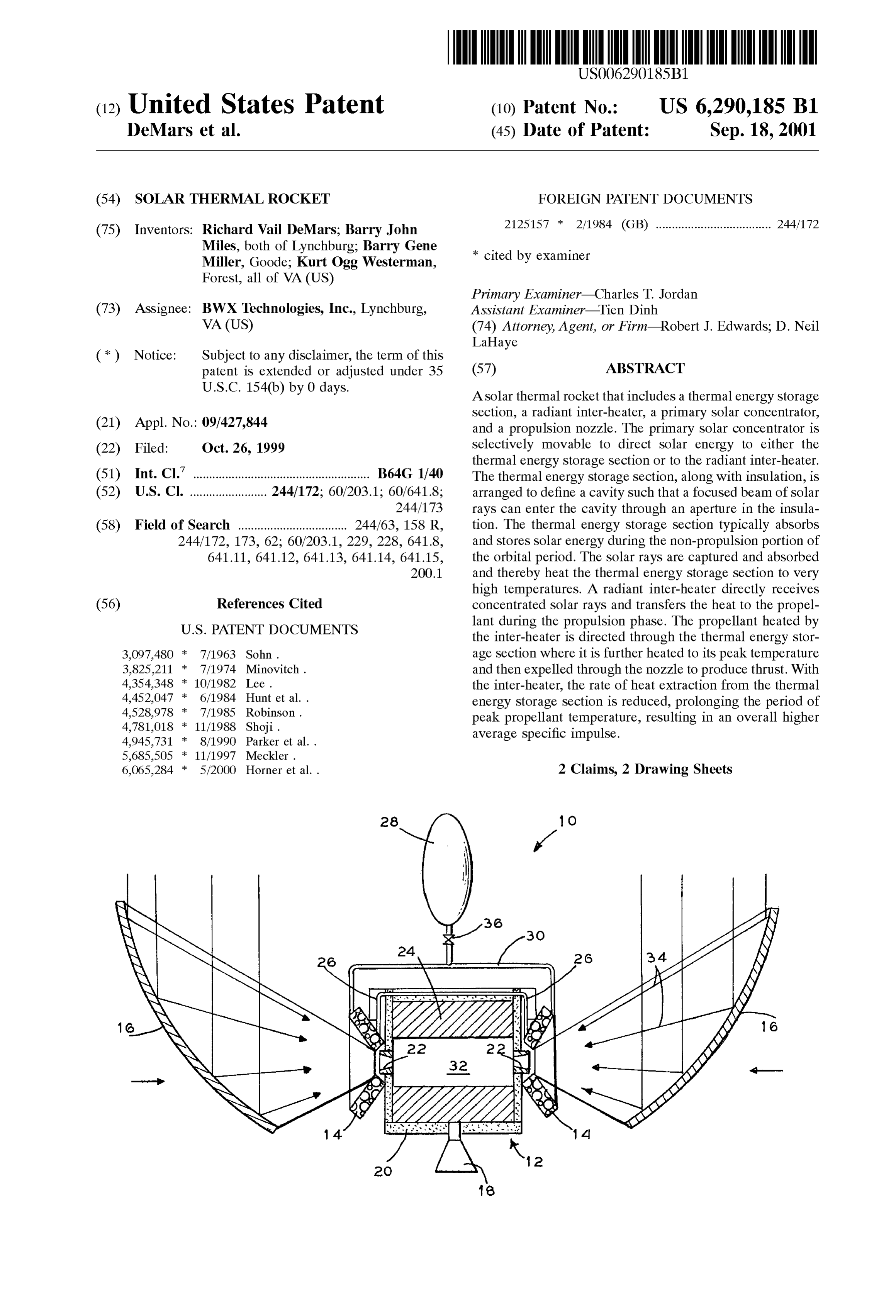
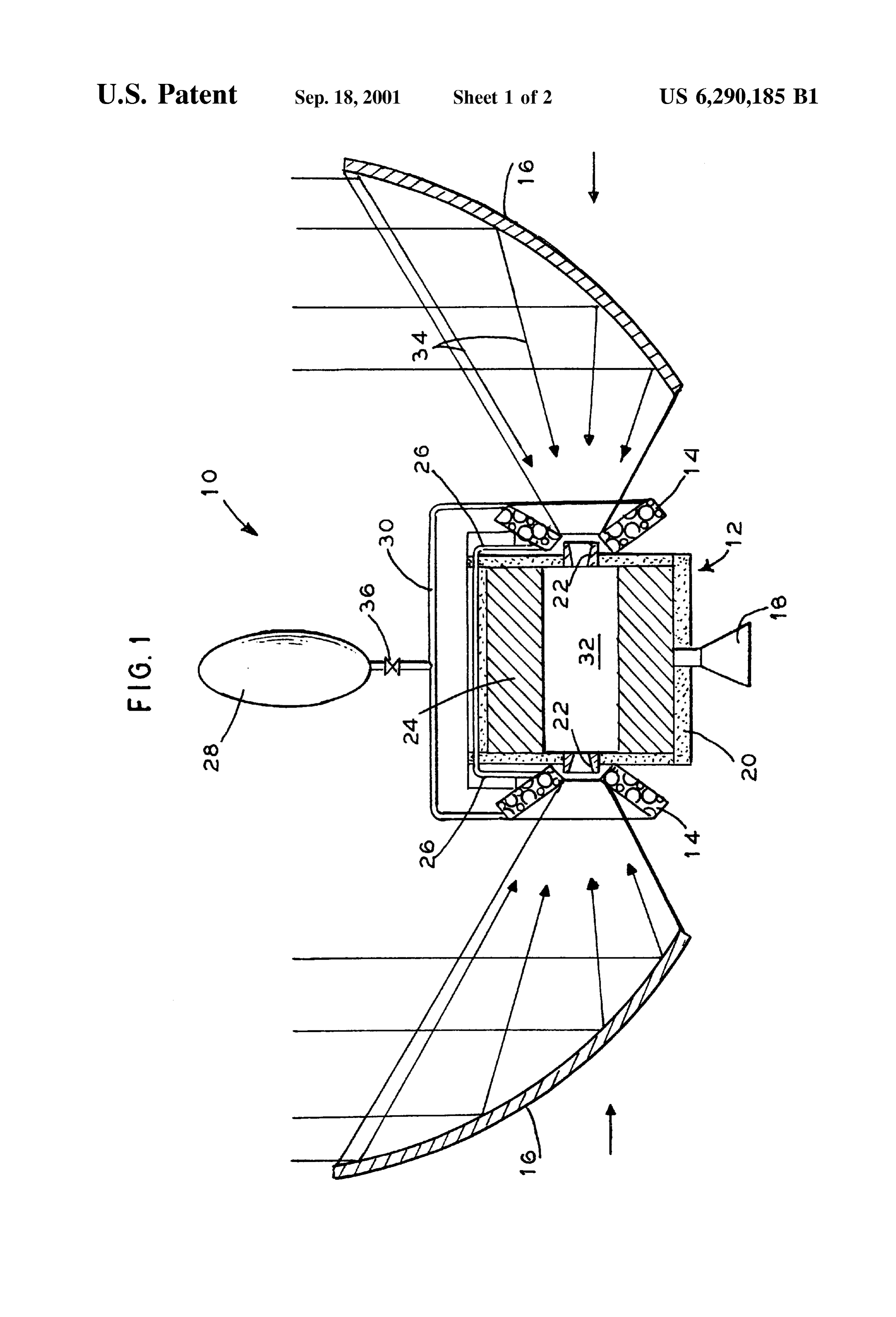
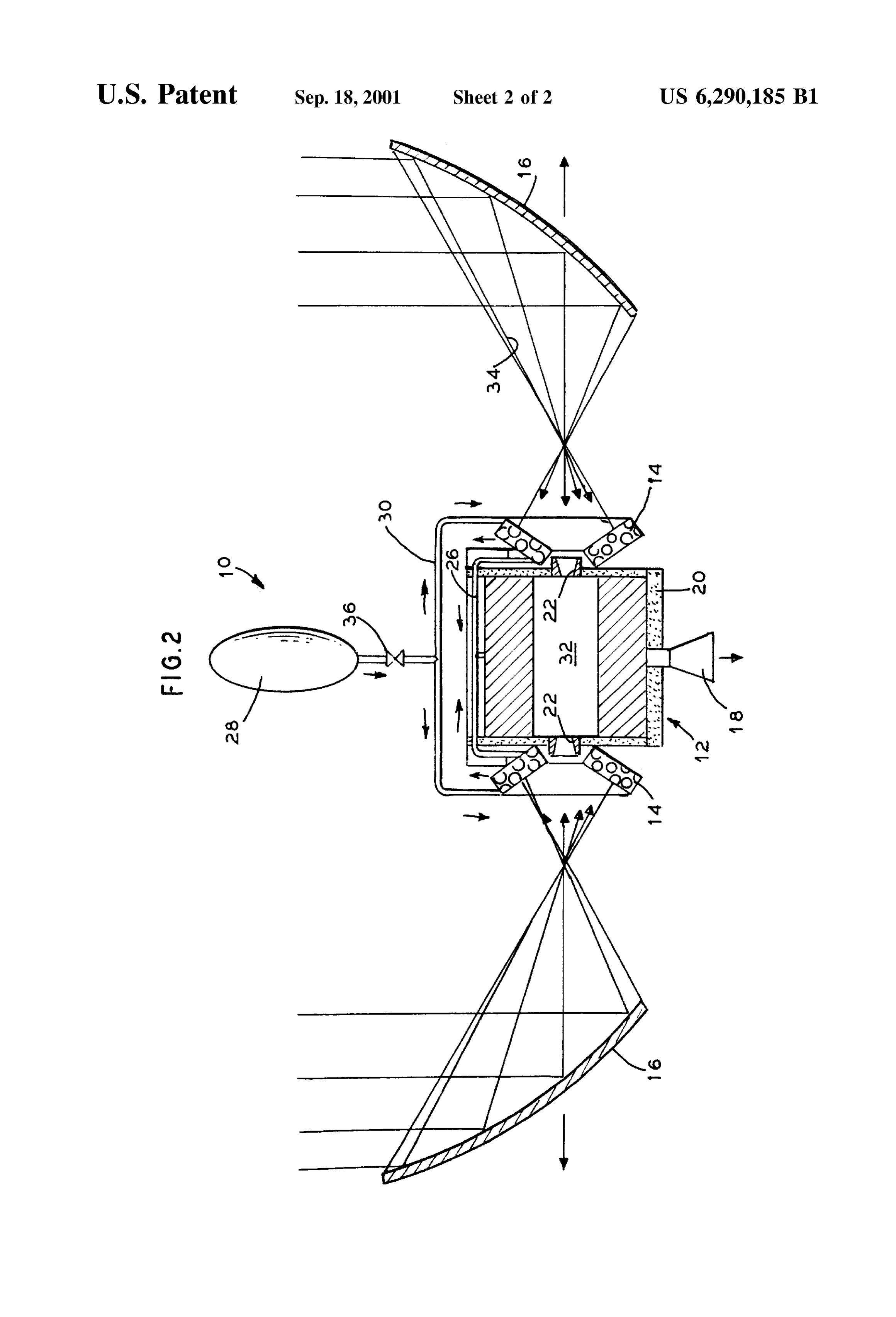
temperature, resulting in an overall higher average specific Operations are conducted as follows. impulse. FIG. 1 illustrates the non-propulsion phase where the BRIEF DESCRIPTION OF THE DRAWINGS primary Solar concentrator 16 is in the first position. In the For a further understanding of the nature and objects of first position, the primary Solar concentrator 16 focuses and the present invention reference should be made to the 15 directs Solar energy to the cavity of the thermal energy following description, taken in conjunction with the accom Storage Section 12 through the Secondary Solar concentrator panying drawings in which like parts are given like refer 22. The lines Striking the concentrator represent the Solar ence numerals, and wherein: rays. The arrows represent the reflected Solar rays that are FIG. 1 is a longitudinal croSS Section at the mid-plane of directed toward the Secondary Solar concentrator. The the invention with the primary Solar concentrator in the reflected Solar rays heat the interior of the thermal energy Storage Section, which Stores the heat for later use during the thermal energy Storage Section heating position.
FIG. 2 is a longitudinal croSS Section at the mid-plane of propulsion approximately phase. Current Storage designs are limited to
the invention with the primary Solar concentrator in the FIG. 2 illustrates the propulsion phase in which the propulsion position for directing Solar energy mainly to the radiant inter-heater. 25 primary Solar concentrator is moved outwardly to its Second position where it projects a significant portion of the
DETAILED DESCRIPTION OF THE reflected Solar rays onto the radiant inter-heater, with the PREFERRED EMBODIMENT remainder entering the thermal energy Storage Section 12 Referring to the drawings, it is seen in FIG. 1 that the through the Secondary concentrator 22. The radiant inter invention is generally indicated by the numeral 10. Solar heater is preferably coated with a high temperature, high thermal rocket 10 is generally comprised of a thermal energy absorptivity material (e.g. refractory carbide). This causes it Storage Section 12, a radiant inter-heater 14, a primary Solar to efficiently absorb and transfer the Solar energy to the concentrator 16, and a propulsion nozzle 18. propellant flowing from the Supply tank 28 prior to entering Thermal energy Storage Sections are generally known but the thermal energy Storage Section 12. The radiant inter will be described for the sake of clarity. Thermal energy 35 heater is preferably designed to heat the propellant gas to a Storage Section 12 contains the thermal energy Storage temperature of 600 to 800 K and up to 1200 K. material and flow channels that guide the propellant through Propellant is released from tank 28 through valve 36 and the Section as it is being heated. The thermal energy Storage travels through piping 30 to the radiant inter-heater 14. The material is typically graphite coated with rhenium and is propellant travels through and is heated by the radiant configured to form a cavity 32 into which the solar rays 17 40 inter-heater 14. The heated propellant then travels through are projected. The thermal energy Section 12 is enclosed in piping 26 into the thermal energy Storage Section 12 where insulation 20. One or more apertures are provided in the it is further heated. The propellant then travels through the insulation for admitting the Solar rays into the cavity 32 propulsion nozzle 18 to produce thrust for propelling the where the energy is captured and in the process heats the rocket or Satellite as desired.
thermal Storage material. A Secondary Solar concentrator 22 45 The invention provides Several advantages. It enhances may be provided in each aperture. The Secondary Solar the already high performance of the thermal energy Storage concentrator 22 Serves to reduce the Size of the aperture by design with a practical, high efficiency radiant inter-heater. further focusing the group of Solar rayS. The Smaller aperture Very high temperatures are produced in the thermal energy minimizes the amount of heat that can radiate out of the Storage Section by positioning the primary Solar concentrator cavity 32. The thermal energy Storage Section 12 is in fluid 50 to project most of the Solar energy into the thermal energy communication with the radiant inter-heater 14 via piping 26 Storage Section during the heat-up phase of the cycle. When that is enclosed by insulation 20. the primary Solar concentrator is repositioned during the The radiant inter-heater 14 is positioned around or adja propulsion phase, the radiant inter-heater more efficiently cent to the Secondary Solar concentrator 22 or the cavity 32 captures the incident Solar power and transferS it to the aperture if a Secondary Solar concentrator 22 is not used. The 55 propellant. At the beginning of the propulsion phase, slightly radiant inter-heater 14 is typically comprised of a coil of higher peak temperatures in the thermal energy Storage metal tubing through which the propellant flows. The pro Section could be obtained by continuing to focus the Solar pellant is heated as it flows through the tubing. beam into the Section. However, by projecting a major The primary solar concentrator 16 is movable between a portion of the Solar energy on the radiant inter-heater, more first position where it directs the Solar rays to the cavity of 60 energy can be captured and used by the apparatus, Signifi the thermal energy Storage Section 12 (FIG. 1) and a second cantly extending the period during which the propellant can position where it directs the majority of the Solar rays to the be heated to near peak temperatures. radiant inter-heater 14 (FIG. 2). Typically, the reflective Another advantage is that the inter-heater operates at leSS Surface of the concentrator 16 is a Segment of a paraboloid, than 1200 K and as Such can be made of conventional and this Surface is positioned Such that the focal point is 65 materials and shapes. With inter-heater temperatures leSS located at or very near the entrance to the Secondary con than 1000 K, austenitic stainless steel is the preferred centrator 22. material. The use of conventional materials reduces fabri
Page 6
S 6 cation cost and Schedule and increases the reliability of the material is used, its Surface must have a high absorptivity of overall apparatus. Solar radiation.
Another advantage is the placement of the inter-heater Because many varying and differing embodiments may be near or around the Secondary concentrator. This allows the made within the Scope of the inventive concept herein taught proportion of the Solar power to be adjusted between the and because many modifications may be made in the inter-heater and the Storage Section by repositioning the embodiment herein detailed in accordance with the descrip primary Solar concentrator. tive requirement of the law, it is to be understood that the A further advantage is that the inter-heater reduces the details herein are to be interpreted as illustrative and not in thermal shock on the thermal energy Storage Section by a limiting Sense.
What is claimed as invention is:
reducing the temperature difference between the hot Storage
Section and the incoming propellant. 1. A Solar thermal rocket, comprising: It should be understood that the configuration illustrated a. an insulated thermal energy Storage Section; and described may be varied. The invention may be com b. a radiant inter-heater, Said radiant inter-heater being in prised of a Single primary Solar concentrator, Secondary 15 fluid communication with a first end of said thermal Solar concentrator, and radiant inter-heater. The thermal energy Storage Section;
energy Storage Section can be divided into two Sections with c. a propulsion nozzle in fluid communication with a each having a primary and Secondary Solar concentrator and Second end of Said thermal energy Storage Section; inter-heater. The thermal energy Storage Section could be a d. a primary Solar concentrator, Said concentrator being monolithic structure with an interior cavity or could be an selectively movable between a first position where assembly of Several modules arranged to form a cavity to Solar energy is directed to Said thermal energy Storage capture the concentrated Solar radiation. More than one Section and a Second position where Solar energy is propulsion nozzle may be used. The radiant inter-heater directed mainly to Said radiant inter-heater, and could be formed from Single or multiple tubes, chambers, or e. a propellant Storage container, Said container being in other flow confinement arrangements that efficiently absorb 25 fluid communication with Said radiant inter-heater. the concentrated Solar radiation and transfer heat to the 2. The rocket of claim 1, further comprising a Secondary flowing propellant. The inter-heater could be constructed of Solar concentrator provided on Said thermal energy Storage any metal, ceramic, or composite that is compatible with the Section.
propellant and interfacing materials over the temperature and pressure range of the operating environment. Whatever
Provenance
- Collection
- Cited prior art
- Original PDF
- patentimages.storage.googleapis.com →
- Filed
- 1999-10-26
- Pages
- 6
- Method
- pdftotext (the PDF's own text layer) + pdftoppm 300dpi page scans
- Source
- Google Patents bibliographic record
- Granted
- 2001-09-18
- Inventors
- Richard Vail DeMars; Barry John Miles; Barry Gene Miller; Kurt Ogg Westerman; BWX Technologies Inc
- Transcribed from
- patentimages.storage.googleapis.com →