patent · US6212873
Gas turbine combined cycle
10 April 2001
Page 1 — bibliographic record
(12) United States Patent (10) Patent No.: US 6,212,873 B1 Sugishita et al. (45) Date of Patent: Apr. 10, 2001
(54) GASTURBINE COMBINED CYCLE FOREIGN PATENT DOCUMENTS
(75) Inventors: Hideaki Sugishita; Hidetaka Mori; 9-317047 12/1997 (JP). Yoshiaki Tsukuda; Kazuo Uematsu; * cited by examiner
Eiji Akita, all of Takasago (JP)
Primary Examiner Hoang Nguyen (73) Assignee: Mitsubishi Heavy Industries, Ltd., (74) Attorney, Agent, or Firm Wenderoth, Lind & Ponack, Tokyo (JP) LLP.
(*) Notice: Subject to any disclaimer, the term of this (57) ABSTRACT patent is extended or adjusted under 35 The invention provides a gas turbine combined cycle Struc U.S.C. 154(b) by 0 days. tured Such that an intermediate cooling device for cooling a compression air discharged from a low pressure compressor, (21) Appl. No.: 09/256,106 So as to reduce a load of a high preSSure compressor, is (22) Filed: Feb. 24, 1999 provided. The gas turbine combined cycle in accordance with the invention is structured Such as to branch water from (30) Foreign Application Priority Data a condenser to a Steam generating device for generating Steam. Exhaust gas discharged from a Steam turbine is
Mar. 4, 1998 (JP) ................................................. 10-051879 condensed to water. Compression air discharged from a low (51) Int. Cl." .................................................... FO2C 6700 preSSure compressor is cooled by being Supplied to an (52) U.S. Cl. ............................................ 60/39.182; 60/728 intermediate cooling device, and is then Supplied to a high (58) Field of Search .................................. 60/39.182,728 preSSure compressor. Steam which heats and operates the Steam turbine is generated by the heat recovered by the (56) References Cited cooling of the compression air in the intermediate cooling device. Accordingly, there can be obtained a gas turbine
5,386,685 2/1995 Fruschi ............................... 60/728 X intermediate cooling type gas turbine combined cycle, but 5,440,871 * 8/1995 Dietz et al. 60/39.182 X exhibiting an improved combined efficiency. 5,724.806 * 3/1998 Horner ............................... 60/728 X 5,784.888 * 7/1998 Termuehlen .................. 60/39.182 X 21 Claims, 3 Drawing Sheets
Page 2
Drawing sheet — no readable text.
Page 3
Drawing sheet — no readable text.
Page 4
Drawing sheet — no readable text.
Page 5
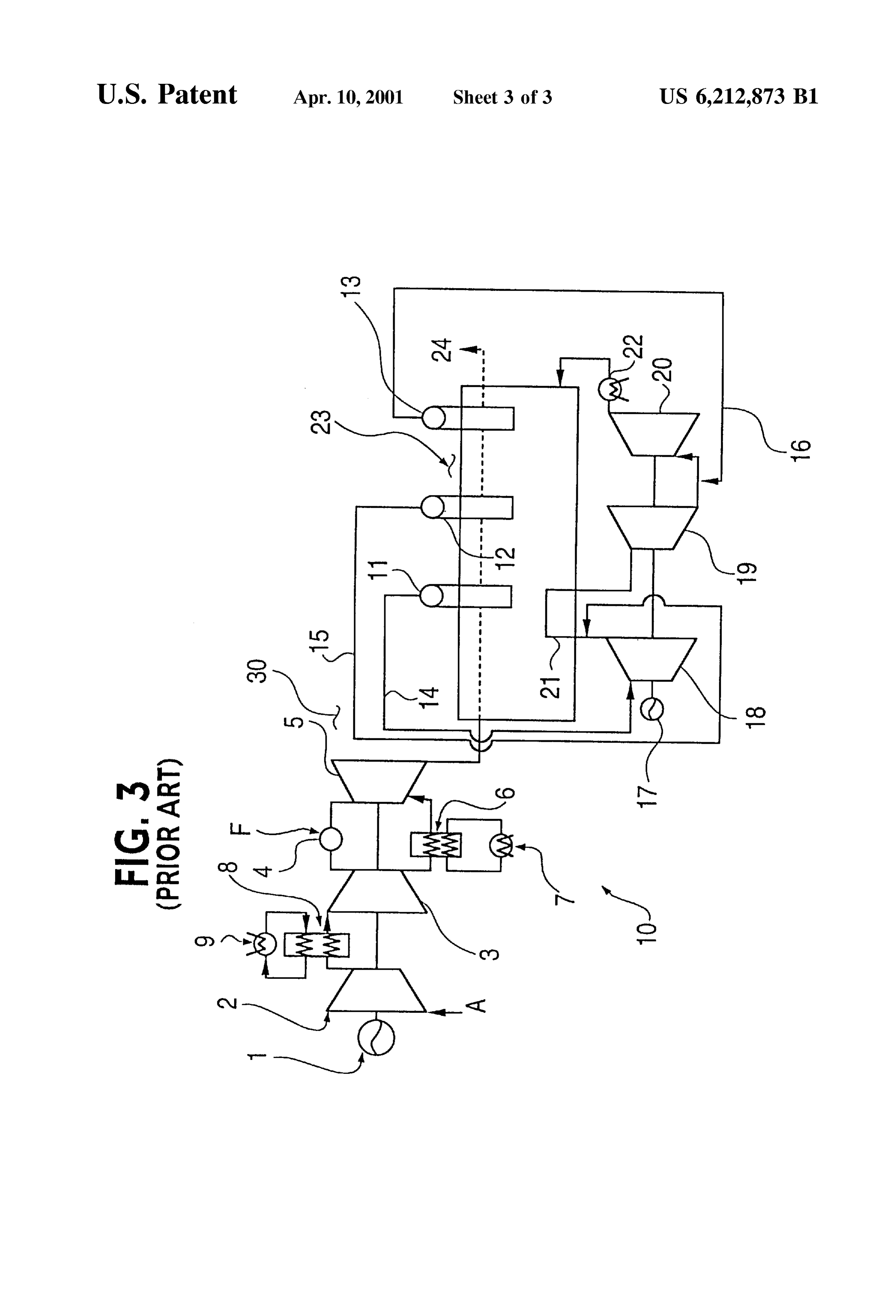
GAS TURBINE COMBINED CYCLE a low pressure compressor 2, a high preSSure compressor 3, a combustion device 4 (combustor), a gas turbine 5, a rotor
BACKGROUND OF TIE INVENTION cooling cooler 6, cooling towers 7 and 9, and an intermediate 1. Field of the Invention cooling device 8. The cooling type gas turbine combined 5 cycle 30 also includes an exhaust gas heat recovery portion
The invention relates to a gas turbine combined cycle or 23 comprising a high pressure Steam generating device 11, power plant which drives a gas turbine by a combustion gas an intermediate Steam generating device 12, a low pressure obtained by blowing a fuel into high pressure air and burning Steam generating device 13, a high pressure Steam pipe 14, the fuel So as to generate power in the gas turbine. A Steam an intermediate preSSure Steam pipe 15, a low pressure Steam turbine is driven by Steam that is generated by recovering pipe 16, a power generator 17, a high pressure Steam turbine heat from an exhaust gas that drives the gas turbine, So as to 18, an intermediate pressure steam turbine 19, a low pres generate power in the Steam turbine. This improves heat Sure Steam turbine 20, a reheater 21 and a condenser 22. efficiency. The gas turbine combined cycle cools compres The high pressure compressor 3, the low pressure com Sion air discharged from a low preSSure compressor before being made into high pressure air by a high preSSure 15 preSSor 2 and the power generator 1 are coaxially connected compressor, So as to make a drive force of the high pressure mentioned turbine to the gas 5 of the gas turbine portion 10, and as below, the gas turbine 5 is structured So as to compressor driven by the gas turbine Small. Heat energy drive the compressors recovered by the cooling is used for driving the Steam ambient air A into a via combustion gas So as to transform predetermined high pressure air for turbine, thereby further improving the heat efficiency. performing a combustion Such that power is generated. 2. Description of the Related Art At first, the ambient air A is Sucked by an intake port of There has been a conventional gas turbine combined the low preSSure compressor 2 driven by the gas turbine 5, cycled or power plant which drives a gas turbine by a compressed in an adiabatic manner and increased to a combustion gas obtained by burning high preSSure air and a predetermined low pressure, and then discharged from a fuel and drives a Steam turbine by Steam generated by an discharge port of the low pressure compressor 2 as a high exhaust gas discharged from the gas turbine. 25 temperature compression air having a temperature equal to This gas turbine combined cycle is structured Such that or more than 190° C.
the gas turbine, driven by the combustion gas, outputs the When introducing this compression air having a high drive force for operating a power generator or the like and temperature into the high pressure compressor 3, the drive drives the compressor for generating the combustion gas force of the high pressure compressor 3 required for increas having a high temperature and a high pressure. The com ing the pressure of the air is increased, whereby the drive preSSor driven by the gas turbine is provided with a low force Supplied from the gas turbine 5 for driving the high preSSure compressor and a high pressure compressor, and preSSure compressor 3 is also increased Such that the drive compresses introduced ambient air in two steps so as to force for driving the generator 1 is reduced. Thus, the make high pressure air, and then Supplies the air to a intermediate cooling device 8 having the cooling tower 9 is combustion device into which fuel is blown So as to generate 35 provided between the discharge port of the low preSSure combustion gas. compressor 2 and the Suction port of the high preSSure That is, the high pressure compressor is structured So as compressor 3 So as to cool the compression air discharged to Suck a high temperature compression air, compressed in from the low pressure compressor 2 to about 100° C. before the low pressure compressor in an adiabatic manner and being introduced into the high pressure compressor 3. reaching a temperature of 190° C. or more, and further 40 The high pressure air increased by the high pressure increase the pressure of the compression air to high pressure compressor 3 is introduced into the combustion device 4, air, and then Supply the air to the combustion device. and mixed with a fuel F introduced to the combustion device Accordingly, the drive force of the high pressure com 4, which is burned So as to produce a combustion gas having preSSor is increased and much of the drive force generated 45 a high temperature and a high pressure, whereby the gas in the gas turbine is consumed, So that the drive force which turbine 5 is driven in the manner mentioned above. the gas turbine can output is reduced. Accordingly, this Further, a part of the high pressure air that is discharged causes a reduction of efficiency of the gas turbine combined from the high pressure compressor 3, or a high pressure air cycle or power plant. extracted from a middle Step of the high pressure compres Therefore, there has been employed an intermediate cool 50 Sor 3 (hereinafter referred to as extracted Steam), is cooled ing type gas turbine combined cycle or power plant to about 200 C. by the rotor cooling cooler 6 and supplied (hereinafter referred to as an intermediate cooling type to an inner portion of a rotor blade or a stator blade of the combined gas turbine cycle or power plant) which is struc gas turbine 5 that is exposed to the high temperature tured So as to cool a high temperature compression air combustion gas passing within the rotor of the gas turbine 5, discharged from the low pressure compressor in an inter 55 thereby cooling the rotor blade or the stator blade from an mediate cooling device, and Supply the compression air inner portion thereof.
cooled to about 100° C. to a high pressure compressor So as Still further, the high temperature exhaust gas driving the to increase the pressure to of the air to a high preSSure. This gas turbine 5, and discharged from the gas turbine 5, is makes the drive force Supplied from the gas turbine for discharged to the ambient air from the chimney 24 via the driving the high pressure compressor Small So as to improve 60 discharged heat recovery portion 23. the magnitude of the drive force Supplied by the gas turbine. Next, in the exhaust gas heat recovery portion 23, a FIG. 3 is a systematic view which shows an intermediate recovery of the heat from the exhaust gas is performed by cooling type gas turbine combined cycle in accordance with Successively passing the exhaust gas from the gas turbine 5 the conventional art. through inner portions of the high pressure Steam generating AS shown in the drawing, an intermediate cooling type 65 device 11, the intermediate pressure Steam generating device gas turbine combined cycle or power plant 30 is constituted 12 and the low pressure Steam generating device 13, which by a gas turbine portion 10 comprising a power generator 1, are arranged in the discharged heat recovery portion 23 So as
Page 6
to respectively generate Steam having a high pressure, an the Stator blade, it is possible to reduce the temperature of intermediate pressure and a low pressure. The Steam having the air at the outlet of the high pressure compressor 3, and the respective preSSures is fed to the high pressure Steam thereby reduce the temperature of the cooling air used for turbine 18, the intermediate pressure steam turbine 19 and cooling the high temperature portion of the gas turbine 5, as the low pressure steam turbine 20, which are coaxially well as reduce the amount of cooling air flowing from the connected respectively by the high pressure Steam pipe 14, high pressure compressor 3 via the rotor cooling cooler 6. the intermediate pressure Steam pipe 15 and the low pressure This reduction in the amount of cooling air causes a steam pipe 16. The steam expands within the turbines 18, 19 reduction of a mixing loSS corresponding to a pressure loSS and 20 So as to rotate the respective Steam turbines, drive the generated when the combustion gas and the cooling air power generator 17 coaxially connected to the Steam flowing within a turbine gas pass are mixed. This results in turbines, and generate electric energy. an increased efficiency and an increased output of the gas Further, at an outlet of the high pressure steam turbine 18 turbine 5, whereby it is possible to increase the output of the the exhaust gas driving the high pressure Steam turbine 18 is gas turbine 5 via an increase in the amount of flow of the mixed with the intermediate preSSure Steam generated in the high pressure air flowing into the combustion device 4 from intermediate pressure Steam generating device 12 and Sup 15 the high pressure compressor 3.
plied by the intermediate pressure steam pipe 15. This (c) Further, it is also possible to increase an efficiency and mixture is heated by the reheater 21 arranged in the exhaust an output of the gas turbine by reducing the temperature of gas heat recovery portion 23, whereby a temperature of this heat discharged from the rotor cooling cooler 6 to a prede mixture flowing into an inlet of the intermediate pressure termined air temperature. The heat discharged from the rotor Steam turbine 19 is increased, Such that an output thereof is cooling cooler 6 results from using the cooler 6 to reduce the increased. temperature of the extracted air used for cooling the high Further, at an outlet of the intermediate preSSure Steam temperature portion of the gas turbine. turbine 19, the exhaust gas driving the intermediate pressure AS mentioned above, in accordance with the conventional steam turbine 19 is mixed with the low pressure steam 25 intermediate cooling type gas turbine combined cycle, there generated in the low pressure Steam generating device 13 is the advantage that it is possible to increase the gas turbine and Supplied by the low pressure Steam pipe 16. This output and the combined output. However, Since the dis mixture is Supplied to the low pressure Steam turbine 20. charged heat from the intermediate cooling device 8 and the Still further, at an outlet of the low pressure steam turbine rotor cooling cooler 6 is discharged to the ambient air by the 20, the exhaust vapor gas discharged from the low pressure cooling towers 7 and 9, the efficiency of the gas turbine 5 is steam turbine 20 is transformed into water by the condenser reduced. Further, Since the discharged heat from the inter 22, which water is Supplied to each of the high preSSure mediate cooling device 8 and the rotor cooling cooler 6 has Steam generating device 11, the intermediate pressure Steam a great disadvantage in that reduction of the efficiency of the generating device 12 and the low pressure Steam generating exhaust gas heat recovery portion 23 is realized, this inter device 13.
35 mediate cooling device 8 has not been actually applied to the
In the intermediate cooling type gas turbine combined conventional gas turbine combined cycle.
cycle 30 structured in the manner mentioned above, it has In this connection, when the compression air discharged been known that the following advantages exist in compari from the low pressure compressor 2 at a temperature of at Son with the Simple gas turbine combined cycle in which a least 190° C. is cooled to about 100° C. by the intermediate conventional intermediate cooling device is not provided. 40 cooling device 8 before being Supplied to the high preSSure (a) It is possible to reduce the power of the high pressure compressor 3, the calories discharged from the cooling compressor 3 that is required for increasing the pressure of tower 9 to the ambient air frequently reaches 5 MW. This the compression air driven by the gas turbine 5 and com results in a disadvantage in that the temperature of the high pressed by the low pressure compressor 2. The compression preSSure air Supplied to the combustion device 4 is reduced, air Supplied to the combustion device 4 is reduced in 45 and the efficiency of the gas turbine 5 is also reduced, in temperature at the inlet of the high pressure compressor 3 via spite of the advantages (a) to (c) mentioned above being the intermediate cooler 8, So that there is an advantage in that obtained. Further, there are disadvantages in that the tem the output Supplied from the gas turbine 5 to the power perature of the exhaust gas from the gas turbine 5 is reduced, generator 1 and the like is increased. the calories recovered by the exhaust gas heat recovery That is, Since the power required for the high pressure 50 portion 23 is reduced, and the drive force output from the compressor 3 can be relatively reduced with respect to the exhaust gas heat recovery portion 23 is also reduced. output of the gas turbine 5, the power required for the high SUMMARY OF THE INVENTION preSSure compressor 3 can be reduced even when the ambient air A is of a high temperature, Such that there is an An object of the invention is to provide a gas turbine advantage in that a reduction of an efficiency of the gas 55 combined cycle or power plant, which can Solve the disad turbine 5 can be restricted. Vantages of the known gas turbine combined cycle that (b) Further, also in the conventional Simple gas turbine exhibits various advantages relative to the Simple gas turbine combined cycle, the high preSSure air extracted from the combined cycle. The gas turbine combined cycle Solves high pressure compressor 3 is used for cooling the high these disadvantages by providing an intermediate cooling temperature portion of the rotor blade, the Stator blade and 60 device, and hence is called an intermediate cooling type gas the like of the gas turbine. However, in the intermediate turbine combined cycle or power plant. The intermediate cooling type gas turbine combined cycle, Since the tempera cooling type gas turbine combined cycle provides for an ture of the air at the inlet of the high pressure compressor 3 improved heat efficiency and output. is reduced by the intermediate cooling device 8, and the high Accordingly, the intermediate cooling type gas turbine preSSure air exiting from the high pressure compressor 3 is 65 combined cycle is structured Such as to recover a cooling cooled by the rotor cooling cooler 6, which air is to be heat which cools a compression air discharged from a low Supplied to the high temperature portion of the rotor blade or preSSure compressor. The heat is recovered by an interme
Page 7
S 6 diate cooling device as the air is being Supplied to a high from the low pressure compressor is cooled before being preSSure compressor. Heat is also recovered by a rotor air Supplied to the high pressure compressor, it is possible to cooler as air exiting the high preSSure compressor is Supplied recover the heat which is recovered in the intermediate through the rotor air cooler to a high temperature portion of cooling device, as well as the heat which is recovered in the a gas turbine. The recovered heat is then conventionally rotor cooling cooler. This enables the extracted air from the discharged to ambient air via a discharged heat recovery high pressure compressor to be cooled, which cooled air is portion, after generating a drive force. Accordingly, a drive then used to cool the high temperature portion of the gas force which can be output from an exhaust gas heat recovery turbine, and then conventionally discharged to the ambient portion can be increased, whereby total efficiency of the air via a discharged heat recovery portion. Further, it is power plant can be improved. possible to convert the heat recovered in the exhaust gas heat In order to achieve the object mentioned above, in accor recovery portion into a large drive force, thereby further dance with the invention, there is provided a gas turbine increasing the drive force capable of being output from the combined cycle Structured Such as to branch a condensed water that is circulated to a Steam generating device. The exhaust improving gas heat recovery portion, and thereby further the efficiency of the power plant.
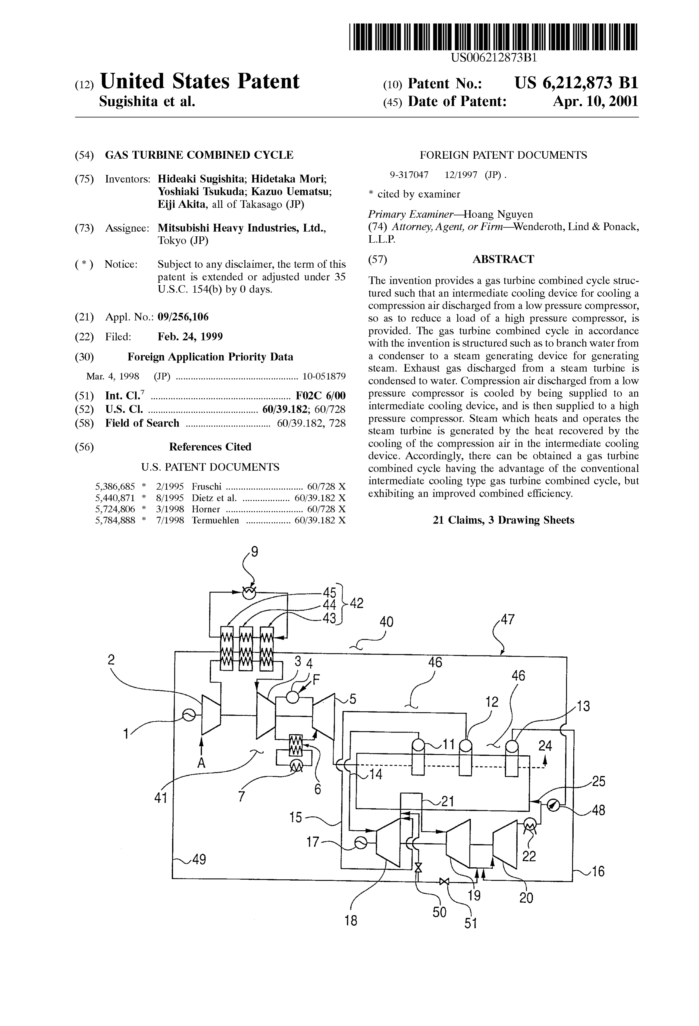
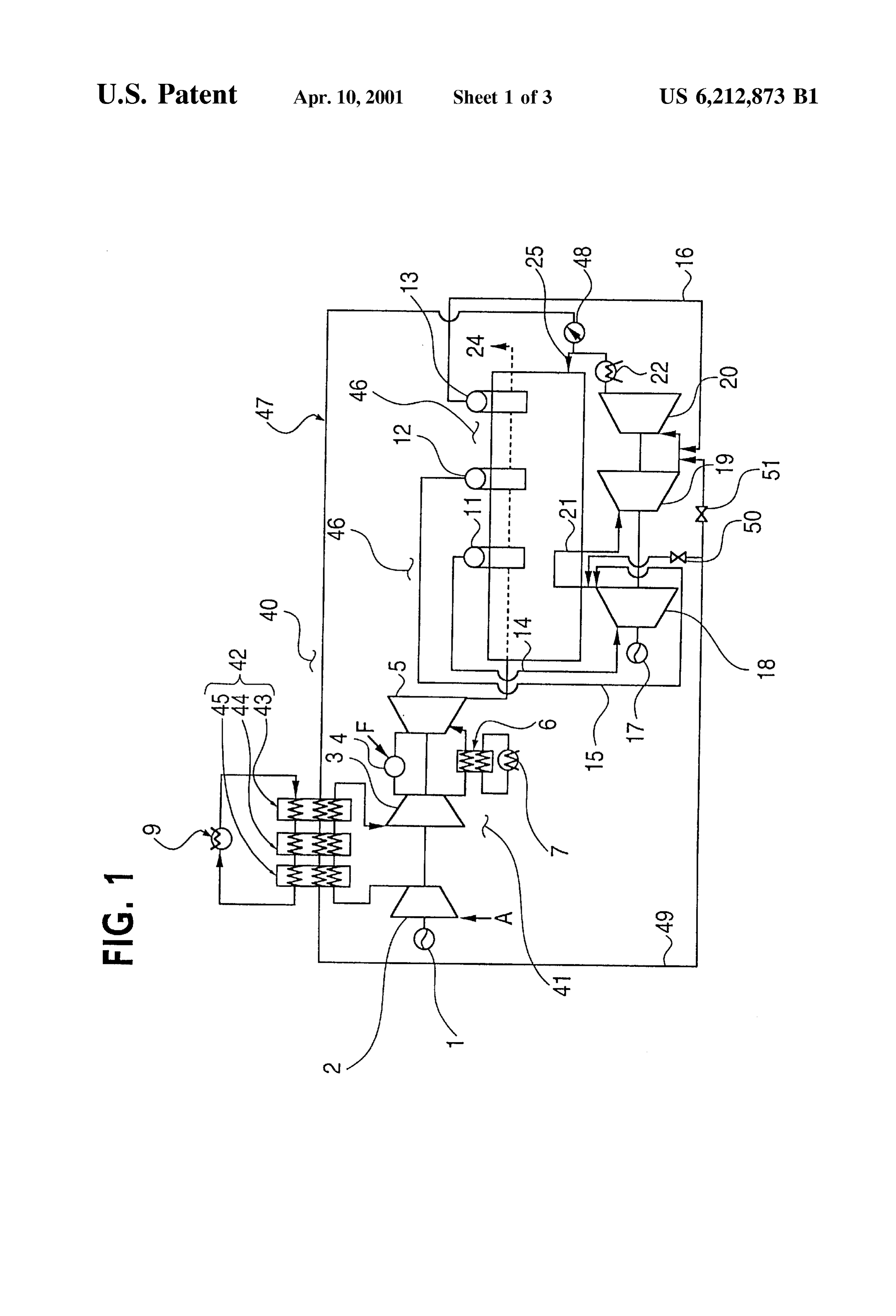
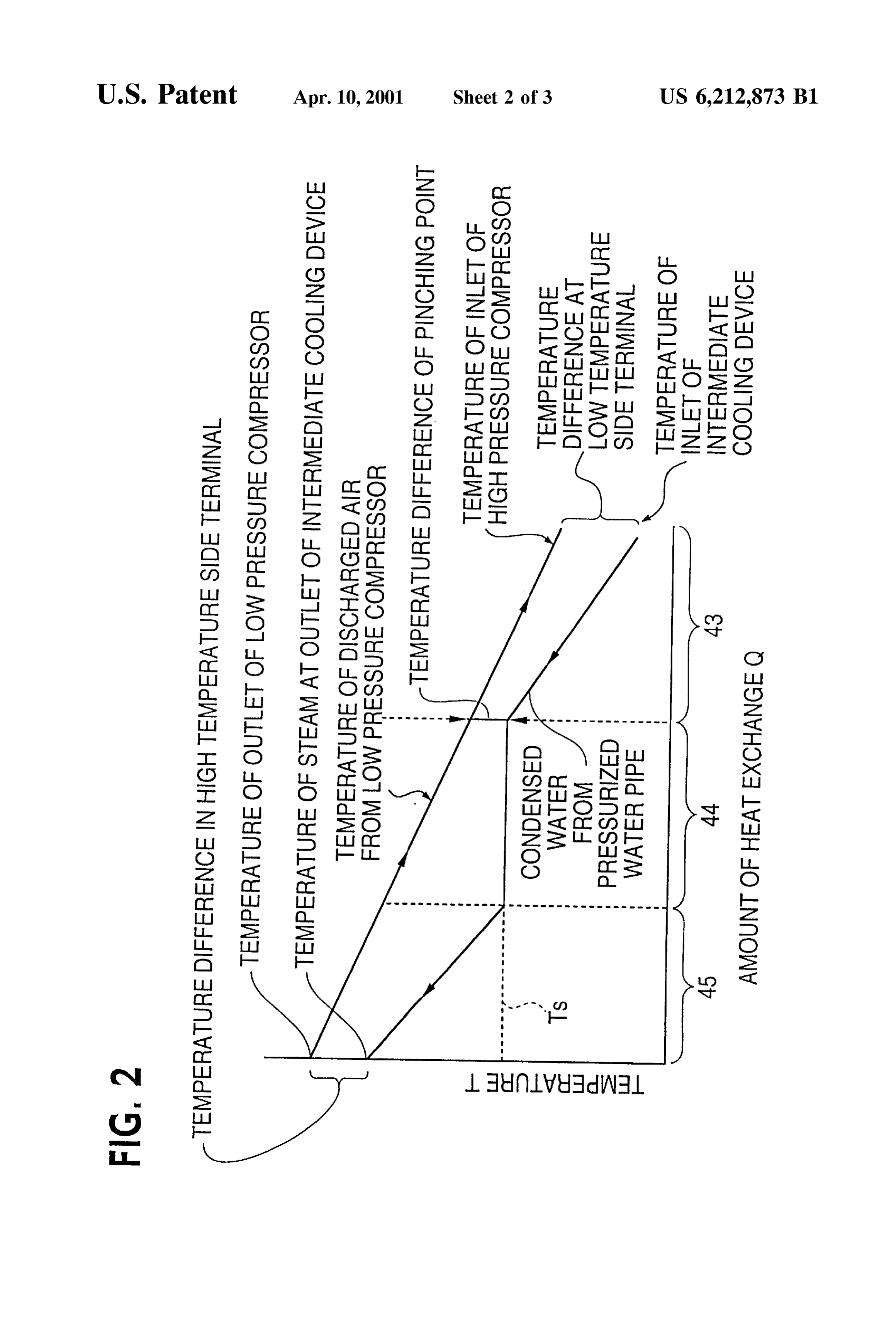
Steam generating device generates Steam by recovering heat 15 from a condenser. The condenser converts exhaust gas that BRIEF DESCRIPTION OF THE DRAWINGS is discharged from a Steam turbine into water. Exhaust gas that is discharged from a gas turbine is Supplied to the Steam FIG. 1 is a systematic view which shows an intermediate turbine. Air that is discharged from a low pressure compres cooling type gas turbine combined cycle as a first embodi Sor is cooled and compressed by a high pressure compressor ment of a gas turbine combined cycle in accordance with the after being Supplied to an intermediate cooling device. And, invention;
Steam is generated which operates a Steam turbine So as to FIG. 2 is a diagram which shows a heat eXchange in an produce an output drive force. The output drive force is intermediate cooling device shown in FIG. 1; and created by heat that is recovered by the cooling of the compression air in the intermediate cooling device. FIG. 3 is a systematic view which shows an intermediate Further, in the gas turbine combined cycle in accordance 25 cooling type combined gas turbine cycle in accordance with with the invention mentioned above, in addition to the the prior art.
Structure mentioned above, it is preferable that the water DESCRIPTION OF THE PREFERRED Supplied to the intermediate cooling device is heated So as to EMBODIMENTS generate Steam. Steam is also generated by heat recovered from a rotor cooling cooler, which cools a part of the high Hereinafter, an embodiment of a gas turbine combined preSSure air discharged from the high pressure compressor. cycle or power plant in accordance with the invention will The rotor cooling cooler heat cools a high temperature be described below with reference to the drawings. portion of the gas turbine, or air extracted from a proper Step of the high pressure compressor. First Embodiment Accordingly, Since the Structure discharges the heat recov 35 FIG. 1 is a systematic view which shows an intermediate ered in the intermediate cooling device and the rotor cooling cooler, while having the advantages (a) to (c) mentioned cooling type gas turbine combined cycle as a first embodi above, there were the disadvantages that the gas turbine invention.gas turbine combined cycle in accordance with the ment of a efficiency was reduced and the efficiency of the exhaust gas heat recovery portion was also reduced. With respect to the 40 In this case, in the drawing, the same reference numerals disadvantages in the intermediate cooling type gas turbine are attached to the same elements as those shown in FIG. 3, combined cycle provided with the intermediate cooling and a detailed explanation thereof will be omitted. device, wherein the discharged heat is recovered in the A gas turbine portion 41 of the intermediate cooling type intermediate cooling device and the rotor cooling cooler and gas turbine combined cycle in accordance with this embodi then discharged to the ambient air after generating a drive 45 ment is provided with the same elements as the gas turbine force, it is possible to increase the drive force and to improve portion 10 as shown in FIG. 3. The turbine portion 41 a total efficiency of the plant. Therefore, it is possible to includes a power generator 1, a low preSSure compressor 2, Solve at least the disadvantage that the efficiency of the a high preSSure compressor 3, a combustion device 4, a gas discharged heat recovery portion in the conventional inter turbine 5, a rotor cooling cooler 6, and cooling towers 7 and mediate cooling type gas turbine combined cycle is reduced. 50 9.
Accordingly, it is possible to make an intermediate cooling Further, in place of the intermediate cooling device 8 type combined gas turbine provided with the intermediate shown in FIG. 3, the gas turbine combined cycle of this cooling device, i.e. a gas turbine combined cycle which can embodiment is provided with an intermediate cooling device Sufficiently exhibit the advantages (a) to (c) mentioned 42 that includes an economizer 43, an evaporator 44 and a above. 55 Super heater 45.
Further, in accordance with the invention, in addition to The gas turbine portion 41 is structured in the same the Structure mentioned above, there is provided a steam manner as that of the gas turbine 10 shown in FIG. 3, turbine which comprises a high pressure Steam turbine, an whereby the high pressure compressor 3 is coaxially con intermediate preSSure Steam turbine and a low pressure nected with the low pressure compressor 2 and the power Steam turbine. Steam generated from water, or from heat 60 generator 1. The compressors are operated by the gas turbine recovered by cooling extracted air that is discharged from 5 which is driven by the combustion gas as mentioned the low pressure compressor, is Supplied to any one of the below. The gas turbine portion 41 generates a predetermined intermediate pressure Steam turbine and the low pressure high preSSure air for burning the ambient air and generating Steam turbine, whereby these Steam turbines are operated power.
and the drive force is improved. 65 However, the intermediate cooling device 42 for cooling That is, in the gas turbine combined cycle in accordance the compression air, discharged from the low preSSure with the invention, Since the compression air discharged compressor 2, from about 190° C. to about 100° C. includes
Page 8
the economizer 43, the evaporator 44 and the Super heater generator 17, which is coaxially connected to the Steam 45. Thus, the heat which deteriorates a heat efficiency of the turbines 18, 19 and 20, so as to generate electric energy. Any conventional intermediate cooling type gas turbine com high temperature gas passing through the low pressure Steam bined cycle 30 is recovered in the intermediate cooling generating device 13, and not fed to the low pressure Steam device 42 and is converted into power in an exhaust gas heat turbine 20, is discharged from chimney 24 into the ambient recovery portion 46 without being discharged to the ambient a.
air. Accordingly, the disadvantage in that the efficiency of Further, in the outlet of the high pressure steam turbine 18 the exhaust gas heat recovery portion 23 is reduced due to the exhaust gas of the high pressure Steam turbine 18 is the provision of the intermediate cooling device 8 as shown mixed with the intermediate preSSure Steam generated in the in FIG. 3, can be avoided. Thus, various advantages related intermediate pressure Steam generating device 12. This to the gas turbine combined cycle 40 can be realized. mixed Steam is Supplied through the intermediate preSSure In the present invention, the cooling tower 9 for discharg steam pipe 15, and thereafter heated by the reheater 21. This ing the recovered heat to the ambient air is provided in the increases the temperature of the Steam at the inlet of the same manner as that shown in FIG. 3. However, the cooling intermediate pressure steam turbine 19. Then, the mixed tower 9 in accordance with the present invention is only used 15 Steam is Supplied to the intermediate preSSure Steam turbine as a back up in case water is not Sufficiently Supplied to the 19, such that the output of the intermediate pressure turbine intermediate cooling device 42 Such that a temperature of preSSure19 is increased. Further, in the outlet of the intermediate the cooling air at an outlet of the high pressure compressor diate pressure Steam turbine 19, the exhaust gas of the interme steam turbine 19 is mixed with the low 3 is increased and a risk of an unacceptably high StreSS for preSSure Steam generated in the low pressure Steam gener a turbine blade is realized when a partial load is applied The ating device 13. This mixed Steam is Supplied through the cooling tower 9 is not used near a rated point of the low preSSure Steam pipe 16, and thereafter Supplied to the intermediate cooling type gas turbine combined cycle 40. low pressure steam turbine 20. In the exhaust gas heat recovery portion 46, there are Further, in the outlet of the low pressure steam turbine 20, provided the Same elements as the exhaust gas heat recovery the exhaust vapor gas discharged from the low preSSure shown in FIG. 3. The exhaust gas heat recovery portion 46 25 Steam turbine 20 is changed to water via condenser 22, includes a high preSSure Steam generating device 11, an which water is to be Supplied to each of the high preSSure intermediate pressure Steam generating device 12, a low Steam generating device 11, the intermediate pressure Steam preSSure Steam generating device 13, a high pressure Steam generating device 12 and the low preSSure Steam generating pipe 14, an intermediate pressure Steam pipe 15, a low device 13.
preSSure Steam pipe 16, a power generator 17, a high Still further, in the exhaust gas heat recovery portion 46 preSSure Steam turbine 18, an intermediate pressure Steam a part of the water to be Supplied from the condenser 22 to turbine 19, a low pressure steam turbine 20, a reheater 21 the Steam generating devices 11, 12 and 13 is branched in the and a condenser 22. outlet of the condenser 22, increased to a predetermined Further, in the exhaust gas heat recovery portion 46, there preSSure via the pressurizing pump 48, and then Supplied to is provided a pressurized water pipe 47 provided in Such a 35 the intermediate cooling device 42 through the pressurized manner as to branch from a condensed water Supply pipe 25 water pipe 47.
for Supplying water from the condenser 22 to each of the The pressurized water Supplied to the intermediate cool Steam generating devices 11, 12 and 13. A preSSurizing ing device 42 at first becomes a Saturated water in the pump 48 for Supplying the water to the intermediate cooling economizer 43, further becomes a Saturated Steam in the device 42 is interposed between the water pipe 47 and the 40 evaporator 44, and finally becomes a heated Steam in the supply pipe 25. Also provided is a steam pipe 49 for Super heater 45.
Supplying heated Steam, obtained by evaporating the water AS mentioned above, the calories which are convention used to recover heat by the intermediate cooling device 42, ally discharged to the ambient air in the cooling tower 9, to the outlet of the high pressure steam turbine 18 and the Supplied to the high pressure compressor 3 by cooling the outlet of the intermediate pressure steam turbine 19. Valves 45 compression air discharged from the low pressure compres 50 and 51 are respectively provided in a connection portion Sor 2, and recovered in the intermediate cooling device 42, of the Steam pipe 49 leading to the outlet of the high preSSure are used for increasing a temperature of the pressurized Steam turbine 18, and a connection portion of the Steam pipe water So as to make heated Steam.
49 leading to the outlet of the intermediate pressure steam Further, the heated Steam includes the exhaust vapor gas turbine 19. 50 of the high pressure steam turbine 18 mixed with the In the exhaust gas heat recovery portion 46, in the same intermediate pressure Steam that is generated in the inter manner as that of the exhaust gas heat recovery portion 23 mediate pressure Steam generating device 12 and Supplied shown in FIG. 3, the heat recovery is performed by succes through the intermediate pressure Steam pipe 15 at the inlet Sively passing the high temperature exhaust gas, discharged of the reheater 21. That is, the steam exiting from the outlet from the gas turbine 5 through the inner portions of the high 55 of the high pressure Steam turbine 18 and flowing through preSSure Steam generating device 11 Such that a high pres the heated steam pipe 49 is heated by the reheater 21, and Sure Steam is generated, the intermediate pressure Steam then supplied to the intermediate pressure steam turbine 19 generating device 12 Such that an intermediate pressure So as to increase the output of the intermediate preSSure Steam is generated, and the low pressure Steam generating steam turbine 19. Alteratively, the exhaust gas of the inter device 13 Such that a low preSSure Steam is generated. The 60 mediate pressure steam turbine 19 is mixed with the low respective Steams are fed to the high pressure Steam turbine preSSure Steam generated in the low pressure Steam gener 18, the intermediate pressure steam turbine 19 and the low ating device 13 and Supplied through the low pressure Steam preSSure Steam turbine 20, which are coaxially connected by pipe 16 into the low pressure steam turbine 20. That is, the the high pressure Steam pipe 14, the intermediate pressure Steam exiting from outlet of the intermediate pressure Steam Steam pipe 15 and the low pressure Steam pipe 16, 65 turbine 19 is supplied to the low pressure steam turbine 20 respectively, so that the steam turbines 18, 19 and 20 are So as to increase the output of the low pressure Steam turbine operated and the output forces thereof drive the power 2O.
Page 9
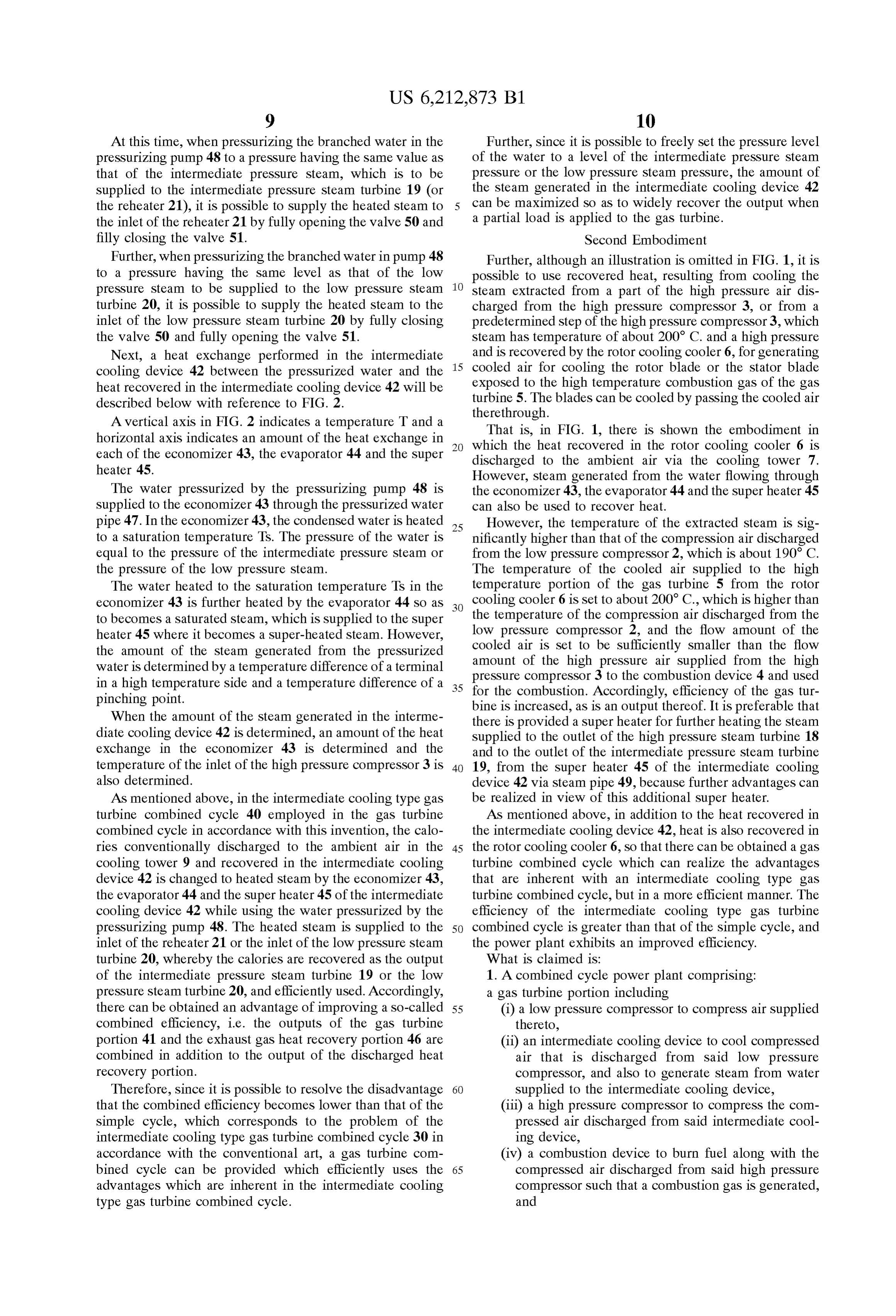
At this time, when pressurizing the branched water in the Further, Since it is possible to freely Set the pressure level preSSurizing pump 48 to a pressure having the same value as of the water to a level of the intermediate pressure Steam that of the intermediate preSSure Steam, which is to be preSSure or the low preSSure Steam pressure, the amount of supplied to the intermediate pressure steam turbine 19 (or the Steam generated in the intermediate cooling device 42 the reheater 21), it is possible to Supply the heated Steam to can be maximized So as to widely recover the output when the inlet of the reheater 21 by fully opening the valve 50 and a partial load is applied to the gas turbine. filly closing the valve 51. Second Embodiment Further, when pressurizing the branched water in pump 48 Further, although an illustration is omitted in FIG. 1, it is to a pressure having the Same level as that of the low possible to use recovered heat, resulting from cooling the preSSure Steam to be Supplied to the low preSSure Steam Steam extracted from a part of the high preSSure air dis turbine 20, it is possible to supply the heated steam to the charged from the high pressure compressor 3, or from a inlet of the low pressure steam turbine 20 by fully closing predetermined Step of the high pressure compressor 3, which the valve 50 and fully opening the valve 51. Steam has temperature of about 200 C. and a high pressure Next, a heat eXchange performed in the intermediate 15 and is recovered by the rotor cooling cooler 6, for generating cooling device 42 between the pressurized water and the cooled air for cooling the rotor blade or the stator blade heat recovered in the intermediate cooling device 42 will be exposed to the high temperature combustion gas of the gas described below with reference to FIG. 2. turbine 5. The blades can be cooled by passing the cooled air therethrough.
A vertical axis in FIG. 2 indicates a temperature T and a That is, in FIG. 1, there is shown the embodiment in horizontal axis indicates an amount of the heat eXchange in which the heat recovered in the rotor cooling cooler 6 is each of the economizer 43, the evaporator 44 and the Super discharged to the ambient air via the cooling tower 7. heater 45. However, Steam generated from the water flowing through The water pressurized by the pressurizing pump 48 is the economizer 43, the evaporator 44 and the Super heater 45 Supplied to the economizer 43 through the pressurized water can also be used to recover heat.
pipe 47. In the economizer 43, the condensed water is heated 25 However, the temperature of the extracted Steam is Sig to a Saturation temperature TS. The pressure of the water is nificantly higher than that of the compression air discharged equal to the pressure of the intermediate pressure Steam or from the low pressure compressor 2, which is about 190° C. the pressure of the low pressure Steam. The temperature of the cooled air Supplied to the high The water heated to the saturation temperature Ts in the temperature portion of the gas turbine 5 from the rotor economizer 43 is further heated by the evaporator 44 so as cooling cooler 6 is set to about 200 C., which is higher than to becomes a Saturated Steam, which is Supplied to the Super the temperature of the compression air discharged from the heater 45 where it becomes a Super-heated steam. However, low pressure compressor 2, and the flow amount of the the amount of the Steam generated from the pressurized cooled air is set to be sufficiently smaller than the flow amount of the high pressure air supplied from the high water is determined by a temperature difference of a terminal preSSure compressor 3 to the combustion device 4 and used in a high temperature Side and a temperature difference of a 35 for the combustion. Accordingly, efficiency of the gas tur pinching point. bine is increased, as is an output thereof. It is preferable that When the amount of the Steam generated in the interme there is provided a Super heater for further heating the Steam diate cooling device 42 is determined, an amount of the heat supplied to the outlet of the high pressure steam turbine 18 eXchange in the economizer 43 is determined and the and to the outlet of the intermediate pressure Steam turbine temperature of the inlet of the high pressure compressor 3 is 40 19, from the Super heater 45 of the intermediate cooling also determined. device 42 Via Steam pipe 49, because further advantages can AS mentioned above, in the intermediate cooling type gas be realized in view of this additional Super heater. turbine combined cycle 40 employed in the gas turbine AS mentioned above, in addition to the heat recovered in combined cycle in accordance with this invention, the calo the intermediate cooling device 42, heat is also recovered in ries conventionally discharged to the ambient air in the 45 the rotor cooling cooler 6, So that there can be obtained a gas cooling tower 9 and recovered in the intermediate cooling turbine combined cycle which can realize the advantages device 42 is changed to heated Steam by the economizer 43, that are inherent with an intermediate cooling type gas the evaporator 44 and the Super heater 45 of the intermediate turbine combined cycle, but in a more efficient manner. The cooling device 42 while using the water pressurized by the efficiency of the intermediate cooling type gas turbine preSSurizing pump 48. The heated Steam is Supplied to the 50 combined cycle is greater than that of the simple cycle, and inlet of the reheater 21 or the inlet of the low pressure steam the power plant exhibits an improved efficiency. turbine 20, whereby the calories are recovered as the output What is claimed is:
of the intermediate pressure steam turbine 19 or the low 1. A combined cycle power plant comprising: preSSure Steam turbine 20, and efficiently used. Accordingly, a gas turbine portion including there can be obtained an advantage of improving a So-called 55 (i) a low pressure compressor to compress air Supplied combined efficiency, i.e. the outputs of the gas turbine thereto, portion 41 and the exhaust gas heat recovery portion 46 are (ii) an intermediate cooling device to cool compressed combined in addition to the output of the discharged heat air that is discharged from Said low pressure recovery portion. compressor, and also to generate Steam from water Therefore, Since it is possible to resolve the disadvantage 60 Supplied to the intermediate cooling device, that the combined efficiency becomes lower than that of the (iii) a high pressure compressor to compress the com Simple cycle, which corresponds to the problem of the pressed air discharged from Said intermediate cool intermediate cooling type gas turbine combined cycle 30 in ing device, accordance with the conventional art, a gas turbine com (iv) a combustion device to burn fuel along with the bined cycle can be provided which efficiently uses the 65 compressed air discharged from Said high preSSure advantages which are inherent in the intermediate cooling compressor Such that a combustion gas is generated, type gas turbine combined cycle. and
Page 10
(v) a gas turbine to be driven by the combustion gas the Steam generated by Said intermediate cooling device to generated by Said combustion device; and Said Steam turbine is to Supply the Steam generated by Said an exhaust gas heat recovery portion including intermediate cooling device to any one of Said intermediate (i) a steam generating device to recover heat from an preSSure Steam turbine and Said low pressure Steam turbine. exhaust gas discharged from Said gas turbine, and 11. The combined power plant according to claim 5, use this recovered heat to generate Steam, wherein Said intermediate cooling device includes a Super (ii) a steam turbine to be driven by the Steam generated heater.
by Said Steam generating device, and 12. The combined power plant according to claim 5, (ii) a condenser to condense an exhaust vapor gas wherein Said intermediate cooling device includes an discharged from Said Steam turbine into water. economizer, an evaporator and a Super heater. 2. The combined power plant according to claim 1, and 13. The combined power plant according to claim 5, further comprising a System to Supply the Steam generated wherein Said Steam turbine includes a high preSSure Steam by Said intermediate cooling device to Said Steam turbine to turbine and a low pressure Steam turbine, and wherein Said drive Said Steam turbine. System to Supply the Steam generated by Said intermediate 3. The combined power plant according to claim 2, and 15 cooling device to Said Steam turbine is to Supply the Steam further comprising a System to Supply water from Said generated by Said intermediate cooling device to an outlet of condenser to Said intermediate cooling device, wherein the Said high pressure Steam turbine and an inlet of Said low water Supplied from Said condenser to Said intermediate preSSure Steam turbine.
cooling device is transformed into the Steam generated at 14. The combined power plant according to claim 13, Said intermediate cooling device. wherein Said Steam turbine further includes an intermediate 4. The combined power plant according to claim 3, preSSure Steam turbine, and wherein Said System to Supply wherein Said System to Supply water from Said condenser to the Steam generated by Said intermediate cooling device to Said intermediate cooling device is also to Supply water from an outlet of Said high preSSure Steam turbine and an inlet of Said condenser to Said Steam generating device, wherein the Said low pressure Steam turbine is also to Supply the Steam water Supplied from Said condenser to Said Steam generating 25 generated by Said intermediate cooling device to Said inter device is transformed into the Steam generated at Said Steam mediate pressure Steam turbine.
generating device. 15. The combined power plant according to claim 2, 5. The combined power plant according to claim 4, wherein Said Steam turbine includes a high preSSure Steam wherein Said System to Supply water from Said condenser to turbine and a low pressure Steam turbine, and wherein Said Said intermediate cooling device and Said Steam generating System to Supply the Steam generated by Said intermediate device includes a branched line, with one branch intercon cooling device to Said Steam turbine is to Supply the Steam necting Said condenser with Said Steam generating device, generated by Said intermediate cooling device to an outlet of and with another branch interconnecting said condenser with said high pressure steam turbine and an inlet of Said low Said intermediate cooling device. preSSure Steam turbine.
6. The combined power plant according to claim 5, and 35 16. The combined power plant according to claim 15, further comprising a System to Supply air discharged from wherein Said Steam turbine further includes an intermediate Said high pressure compressor to a cooler and then to a high preSSure Steam turbine, and wherein Said System to Supply temperature portion of Said gas turbine in order to cool the the Steam generated by Said intermediate cooling device to high temperature portion of Said gas turbine. an outlet of Said high preSSure Steam turbine and an inlet of 7. The combined power plant according to claim 6, and 40 Said low pressure Steam turbine is also to Supply the Steam further comprising a System to Supply Steam generated at the generated by Said intermediate cooling device to Said inter high temperature portion of Said gas turbine, due to cooling mediate pressure Steam turbine.
thereof Via the air passed to and from the cooler, to Said 17. The combined power plant according to claim 2, Steam turbine for driving Said Steam turbine. wherein Said Steam turbine includes a high preSSure Steam 8. The combined power plant according to claim 7, 45 turbine, an intermediate pressure Steam turbine and a low wherein Said Steam turbine includes a high preSSure Steam preSSure Steam turbine, and wherein Said System to Supply turbine and a low pressure Steam turbine, and wherein Said the Steam generated by Said intermediate cooling device to System to Supply the Steam generated by Said intermediate Said Steam turbine is to Supply the Steam generated by Said cooling device to Said Steam turbine is to Supply the Steam intermediate cooling device to any one of Said intermediate generated by Said intermediate cooling device to an outlet of 50 preSSure Steam turbine and Said low pressure Steam turbine. Said high pressure Steam turbine and an inlet of Said low 18. The combined power plant according to claim 2, preSSure Steam turbine. wherein Said intermediate cooling device includes a Super 9. The combined power plant according to claim 8, heater.
wherein Said Steam turbine further includes an intermediate 19. The combined power plant according to claim 2, preSSure Steam turbine, and wherein Said System to Supply 55 wherein Said intermediate cooling device includes an the Steam generated by Said intermediate cooling device to economizer, an evaporator and a Super heater. an outlet of Said high pressure Steam turbine and an inlet of 20. The combined power plant according to claim 1, Said low pressure Steam turbine is also to Supply the Steam wherein Said intermediate cooling device includes a Super generated by Said intermediate cooling device to Said inter heater.
mediate pressure Steam turbine. 60 21. The combined power plant according to claim 1, 10. The combined power plant according to claim 5, wherein Said intermediate cooling device includes an wherein Said Steam turbine includes a high preSSure Steam economizer, an evaporator and a Super heater. turbine, an intermediate pressure Steam turbine and a low preSSure Steam turbine, and wherein Said System to Supply k k k k k
Provenance
- Collection
- Cited prior art
- Original PDF
- patentimages.storage.googleapis.com →
- Filed
- 1999-02-24
- Pages
- 10
- Method
- pdftotext (the PDF's own text layer) + pdftoppm 300dpi page scans
- Source
- Google Patents bibliographic record
- Granted
- 2001-04-10
- Inventors
- Hideaki Sugishita; Hidetaka Mori; Yoshiaki Tsukuda; Kazuo Uematsu; Eiji Akita; Mitsubishi Heavy Industries Ltd
- Transcribed from
- patentimages.storage.googleapis.com →